Murdock GRT75-PF-RFS User manual

INSTALLATION INSTRUCTIONS FOR GRT75-PF-RFS PET FOUNTAIN
WATER COOLERS
I N S TA L L AT I O N / M A I N T E N A N C E I N S T R U C T I O N S
MURDOCK MFG. • 15125 Proctor Avenue • City of Industry, CA 91746 USA
Phone 800-453-7465 or 626-333-2543 • Fax 626-855-4860 • www.murdockmfg.com Member of
Please visit www.murdock.com
for most current specifications.
Important: Read all instructions and refer to local codes
prior to installation.
lLocal soil conditions may require more gravel for
drainage.
lIt is recommended to include a supply stop
appropriately located on the supply line.
lAn in-line PRV installed on the supply line is
recommended to ensure a working water pressure of 40-
60 psi.
l A water filter should be installed on the supply line if
sediment or mineral content is a problem.
lProvide 30" x 30" x 6" deep concrete pad minimum.
Prepare trench for water supply line and waste line (if
required). At fountain location prepare hole to trench depth
and large enough for a person to work. Lay supply and
waste into trench allowing extra length to be trimmed
during hook-up.
Depending on code and design requirements, drain may
be open, French or sanitary connection. For French drain,
place a minimum of three cubic feet of gravel under drain
opening. Local soil conditions may require more gravel
drainage.
Refill trench and hole, compacting back fill as required.
Leave sufficient depth in hole to accommodate concrete
pour.
Page 1 of 3
9938-159-M01 07/21/14
Valve Specifications:
Minimum/Maximum Pressure:
30/100 PSI
Prepare the slab area surrounding fountain spreading and
compacting gravel as necessary. Prepare form
approximately 6" diameter to protect supply and waste
stub outs.
If required, fix 1/4”-20 UNC L-bolt anchors by others in
position arranging L-bolts according to pattern indicated
and pour concrete to grade. Leave enough thread for
mounting base. Ensure concrete top surface is flat and
level. If concrete has cured use appropriate ½” concrete
anchoring hardware by others following the manufacturer's
installation recommendations.
CONTEMPORARY DRINKING FOUNTAINS
I N S TA L L AT I O N / M A I N T E N A N C E I N S T R U C T I O N S
For freeze resistant option refer to
-FRU manual #9938-340-0M1.
`
4"
2" PVC DWV
RECOMMENDED
MINIMUM 3 CUBIC FEET OF
POROUS GRAVEL FILL
Ø9
16"
Ø6"
PUSHBUTTON
ORIENTATION
77
8"
TYP
MOUNTING BASE DETAIL
BUBBLER
ORIENTATION
GRAVEL
EARTH
GRAVEL
WATER
SUPPLY
FROST LINE
Ø13"
3
8" OD x 4" LONG
COPPER TUBE
30" x 30" x 6" DEEP
MIN. CONCRETE PAD
Ø111
8"
4"

MURDOCK MFG. • 15125 Proctor Avenue • City of Industry, CA 91746 USA
Phone 800-453-7465 or 626-333-2543 • Fax 626-855-4860 • www.murdockmfg.com Member of
Please visit www.murdock.com
for most current specifications.
Allow concrete to cure before completing installation.
Remove basin from pedestal and set aside. Align
anchoring studs to pedestal mounting holes and secure
pedestal to slab. To ensure plumb installation, lay a bubble
level on fountain bowl and adjust using shims or washers
until unit is level.
Make up connections to 3/8" OD (1/4" nominal) x 4" long
copper tube with inline Y-strainer. Make up waste
connection to 1-1/4" OD tailpiece provided.
Turn on water supply and test operation of bubbler by
depressing button and adjust flow rate as required. Check
all connections for leaks.
Turn on water supply and test for proper operation and
checking for leaks.
FYI: Protect exposed valve assembly, tubing and tube
openings to prevent damage to equipment or to prevent
tubes from becoming filled with soil or debris.
Rough-in water supply for 3/8" OD (1/4" nominal) x 4" long
copper tube connected to inline Y-strainer inlet provided. A
supply stop by others is recommended.
Test operation of bubbler by depressing button and adjust
flow rate as required. Check all connections for leaks.
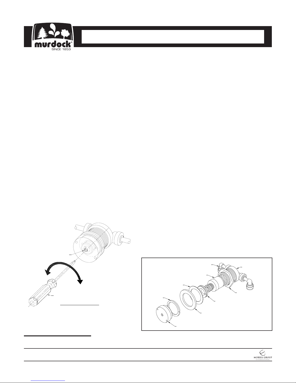
All normal maintenance is done from above ground.
vAlways shut off water supply when doing any
maintenance.
vTo remove pushbutton assembly remove bowl
from housing. From inside of the housing, remove
inlet and outlet lines from push-in ports of valve
body. Using a spanner wrench remove pushbutton
and retaining ring.
vTo replace regulator, use a spanner wrench to
remove pushbutton and retaining ring from the
flange collar. Use a spanner wrench to remove
retainer from the inside of the flange collar. Remove
regulator, insert new regulator and align ports to new
regulator with mating ports of valve body then
replace retaining ring.
vTo access bubbler, remove bowl from housing
assembly. Remove bubbler plug with a spanner
wrench and remove nut holding bubbler in place.
vRe-assemble in reverse order. When replacing
inlet and outlet lines, ensure to insert supply line into
valve port labeled “IN”. Ensure plastic lines are not
kinked when fountain is reassembled.
WATER COOLERS
I N S TA L L AT I O N / M A I N T E N A N C E I N S T R U C T I O N S
CONTEMPORARY DRINKING FOUNTAINS
I N S TA L L AT I O N / M A I N T E N A N C E I N S T R U C T I O N S
Valve Body w/
Flange Collar
Brass Nut
Regulator
Retainer
Fiber Ring
Rubber Gasket
Retaining
Ring
Pushbutton
1/4" Push-In
Elbows
Page 2 of 3
9938-159-M01 07/21/14
INCREASE
FLOW
DECREASE
FLOW
Ø3/16"
HOLE
SLOTTED
SCREWDRIVER
FLOW ADJUSTMENT

PUSH-IN FITTING INSTALLATION
NOTE: FITTINGS AND TUBE SHOULD BE KEPT
CLEAN, BAGGED AND UNDAMAGED PRIOR TO
INSTALLATION.
2. Pull on the fitted tubing to ensure it is secure. Tube
should not come free from the fitting. Water test the
connection assembly prior to leaving the site to ensure
there are no leaks.
DISCONNECTING THE TUBE:
To disconnect the tube from the fitting ensure that the
water line is depressurized. Push collet square towards
the push-in fitting body and hold. While holding the collet
in, pull on the PE tubing to remove from the push-in fitting.
TO CUT TUBE:
Cut to fit length of 1/4” PE tubing and remove any burrs
or sharp edges. Ensure that the outside diameter is free
from score marks. Tube ends should be square.
INSERTING THE TUBE:
1. Firmly and fully insert the tubing end into the push-in
fitting up to the tube stop located approximately ½”
deep.
COLLET
COLLET
O-RING
O-RING
TUBE STOP
COLLET
COLLET
COLLET
WATER COOLERS
I N S TA L L AT I O N / M A I N T E N A N C E I N S T R U C T I O N S
CONTEMPORARY DRINKING FOUNTAINS
I N S TA L L AT I O N / M A I N T E N A N C E I N S T R U C T I O N S
Page 3 of 3
9938-159-M01 07/21/14
MURDOCK MFG. • 15125 Proctor Avenue • City of Industry, CA 91746 USA
Phone 800-453-7465 or 626-333-2543 • Fax 626-855-4860 • www.murdockmfg.com Member of
Please visit www.murdock.com
for most current specifications.


Table of contents
Other Murdock Pet Care Product manuals