manuals.online logo
Brands
  1. Home
  2. •
  3. Brands
  4. •
  5. Murphy
  6. •
  7. Test Equipment
  8. •
  9. Murphy PowerView PV-101 User manual

Murphy PowerView PV-101 User manual

1010585
09-30-10
Section 78
PowerView™- Model PV101 V2.2 – Fuel Sender Calibration
Setting Fuel Level Analog Input
Introduction
This option enables the operator to configure the PV101 to accept the optional Murphy Fuel Sender (Model ES2F
recommended) for fuel level information or to program the unit to accept the non-Murphy fuel sender*.
The PV101 is set from the factory to accept a backlight dimmer input. These instructions show exactly what needs
to be completed to set the PV101 analog input to read Model ES2F Murphy Fuel Sender and how to program the
unit for use with a non-Murphy fuel sender*.
*A linear curve is used to calibrate a non-Murphy fuel sender.
Navigation Buttons
MENU
Pressing [MENU] will take you the menu or it will exit the option, return the display to
the UTILITIES MENU and discard any changes.
LEFT ARROW
Pressing [LEFT ARROW] will decrement the number.
RIGHT ARROW
Pressing
[RIGHT ARROW]
will increment the number.
ENTER
Pressing
[Enter]
will select the option displayed much like the ENTER key on a keyboard.
Location
To begin the process, locate the ANALOG INPUT option is located in the Utilities menu.
Select ANALOG INPUT
Select Fuel Level
The next screen displayed is the BACKLIGHT DIMMER/FUEL LEVEL selection screen.
Select FUEL LEVEL.
(2)
Using the Murphy Fuel Sender
The next screen displayed is the FUEL SENDER SETUP screen. The PV101 ships from the factory set
to be used with a Murphy fuel sender. The FUEL SETPOINTS OFF must be shown to work with a
Murphy fuel sender. Press the right and left arrow keys to navigate the menu. There are two pages to
this screen.
NOTE:
When Fuel Setpoints OFF is set, these screens are displayed but they are not
available for modification. For a non-Murphy fuel sender, see the USING A NON-
MURPHY FUEL SENDER in this document.
NOTE:
The asterisk indicates that the setpoint has been set.
Continue to press the right arrow key to scroll the menu and to see page two of this screen. It contains the
following selections:
(3)
Show Fuel Setpoints
The Murphy Standard Fuel Sender settings are preloaded in the device. To view these settings select
SHOW
FUEL SETPOINTS
.
The following screen is displayed:
NOTE: The numbers displayed on the above screen are Murphy Standard settings.
(4)
Low Fuel Level Setpoint
The next screen displayed is the LOW FUEL SETPOINT screen. The default setting is 10%. This
setting enables the PV101 to generate a DTC (Diagnostic Trouble Code) displaying low fuel level.
Adjusting Low Fuel Level Setting
To change the Low Fuel Level setpoint, use the left and right arrows to increase or decrease the set point. Select
[MENU]
to cancel or
[ENTER]
to confirm the setpoint.
NOTE:
To change the setpoint from backlight dimmer input to fuel level input the
[ENTER/OK]
selection must be made.
Using a Non-Murphy Fuel Sender
The next screen displayed is the
FUEL SENDER SETUP
screen. The
FUEL SETPOINTS ON
must be shown to
work with a non-Murphy fuel sender. With the
FUEL SETPOINTS ON
displayed, the unit can be set to use a non-
Murphy Fuel Sender.
NOTE:
The Murphy Standard setpoints must be cleared before continuing.
(5)
Clear Fuel Setpoints
Use the right arrow key to scroll down to page 2 and select
CLEAR FUEL SETPOINTS
.
This will clear the Murphy
Standard settings.
NOTE:
The SET EMPTY POINT, SET 1/4 POINT, SET 1/2 POINT, SET 3/4 POINT and
SET FULL POINT must be programmed before continuing.
Set Empty Point
First select SET EMPTY POINT with fuel tank empty.
NOTE: The fuel tank must be empty to begin this process.
NOTE: Once the setpoints have been cleared, the asterisks are removed.
(6)
The following screen is displayed. Then set the resistive value. It represents the Empty point from the non-Murphy
fuel sender that must be sent to the PV101. While sending the resistive value, select
[YES]
and the PV101 will
have a new low fuel setpoint setting.
Once the new settings are set, the menu will be displayed.
NOTE: Once the setpoint has been set, an asterisk is displayed to the right of the setpoint.
Set 1/4 Point, 1/2 Point, and 3/4 Point
Add fuel to 25% of the tank’s capacity and select the quarter tank set the 1/4 point setpoint.
The following screen is displayed.
Select [YES] while sending the resistive value.
(7)
Set Remaining Setpoints
Add fuel to 50% of the tank’s capacity to set the 1/2 point setpoint and 75% of the tank’s capacity to set the 3/4
point setpoint.
Set Full Point
Add fuel to fill the tank to its full capacity and select SET FULL POINT.
The following screen is displayed and now the resistive value that represents the Full point from the non-Murphy
fuel sender must be sent to the PV101. While sending the resistive value, select
[YES]
and the PV101 will have a
new Full fuel setpoint setting.
Now that the Non-Murphy fuel sender calibration process is completed, the FUEL SENDER SETUP SCREEN will
be displayed. Select
FUEL LEVEL
.
(8)
Low Fuel Level Setpoint
The next screen displayed is the LOW FUEL SETPOINT screen. The default setting is 10%. This enables the
PV101 to generate a DTC (Diagnostic Trouble Code) that displays the low fuel level.
Adjusting Low Fuel Level Setting
To change the Low Fuel Level setpoint, use the left and right arrows to increase or decrease the setpoint. Select
the menu button to cancel or the enter button to confirm. To change the setpoint from backlight dimmer input to fuel
level input the enter/OK must be selected.
Show Fuel Setpoints
To Sender settings are preloaded in the device. To view these settings select
SHOW FUEL SETPOINTS
.
(9)
(10)
The following screen is displayed:
NOTE:
The numbers displayed on the above screen are examples only. The numbers
displayed on the newly set PV101 will be different.
NOTE:
Once these setpoints are complete, you can add them to your configuration via the
Configuration tool and they can become default values.

Other manuals for PowerView PV-101

1

Other Murphy Test Equipment manuals

Murphy L150 User manual

Murphy

Murphy L150 User manual

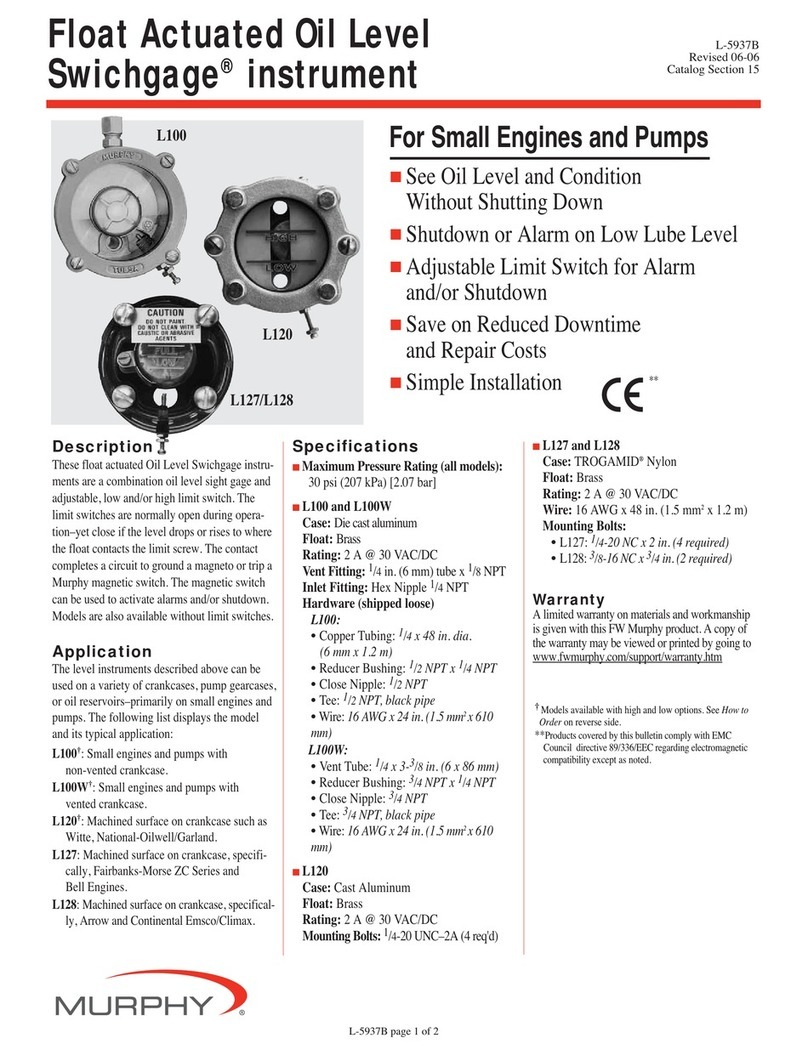
Murphy L-5937B User manual

Murphy

Murphy L-5937B User manual

Popular Test Equipment manuals by other brands

Chroma A195001 user manual

Chroma

Chroma A195001 user manual

Nieaf-Smitt RCT-S user manual

Nieaf-Smitt

Nieaf-Smitt RCT-S user manual

Chauvin Arnoux C.A 6423 user manual

Chauvin Arnoux

Chauvin Arnoux C.A 6423 user manual

Associated Equipment 6054 Instructions for use

Associated Equipment

Associated Equipment 6054 Instructions for use

Daystrom Heathkit CAPACI-TESTER CT-1 Assembling and using

Daystrom

Daystrom Heathkit CAPACI-TESTER CT-1 Assembling and using

Hantek 500MSa/s introduction

Hantek

Hantek 500MSa/s introduction

norbar 43222 installation guide

norbar

norbar 43222 installation guide

Actron OMEGA Series Assembly instructions

Actron

Actron OMEGA Series Assembly instructions

Kikusui PFX2731S Operation manual

Kikusui

Kikusui PFX2731S Operation manual

norbar TWL 1500 Operator's handbook

norbar

norbar TWL 1500 Operator's handbook

InstroTek Auto_SCB operating manual

InstroTek

InstroTek Auto_SCB operating manual

Nex-tech DTW Series user manual

Nex-tech

Nex-tech DTW Series user manual

Tektronix PRISM MPI2-10 Assembly/installation instructions

Tektronix

Tektronix PRISM MPI2-10 Assembly/installation instructions

Dycon D2330 user manual

Dycon

Dycon D2330 user manual

Bear Technologies EXP-USB2 user manual

Bear Technologies

Bear Technologies EXP-USB2 user manual

axing BZU 10-02 basic-line Operation instructions

axing

axing BZU 10-02 basic-line Operation instructions

Sonel LKZ-1000 user manual

Sonel

Sonel LKZ-1000 user manual

Hitachi V-211 Service manual

Hitachi

Hitachi V-211 Service manual

manuals.online logo
manuals.online logoBrands
  • About & Mission
  • Contact us
  • Privacy Policy
  • Terms and Conditions

Copyright 2025 Manuals.Online. All Rights Reserved.