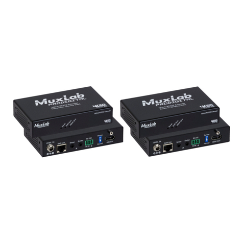
2. Verify that the distance between the HDMI Transmitter and Receiver is within
MuxLab specifications (see Specifications table).
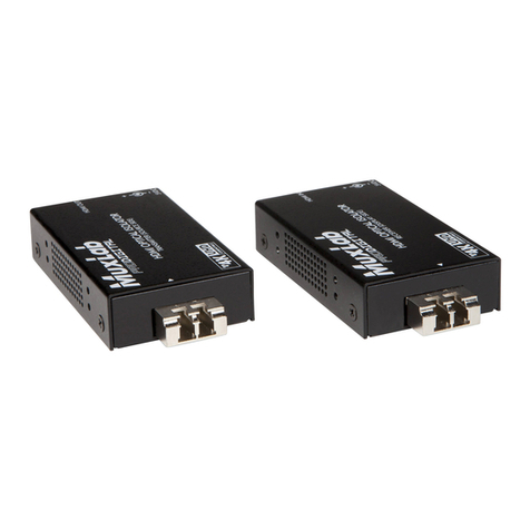
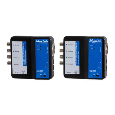
3. To install the Transmitter:
3a. Connect the Transmitter to the HDMI video source with an HDMI compliant
cable.
3b. Connect one (1) lengths of Cat 5e/6 (or higher) grade UTP cables to
RJ45 LINK connectors on the Transmitter.
4. To install the Receiver:
4a. Connect the Receiver to the HDMI display equipment with an HDMI compliant
cable.
Note: When used with MuxLab’s Multimedia Matrix Switch, please consult the
Matrix Switch Installation Guide.
4b. Connect the one (1) Cat 5e/6 cables to RJ45 LINK connectors on the Receiver.
5. Connect the 48VDC power supply to the Receiver first, and then plug the power
supply into an AC power outlet. If power is present, the green power LED of the
Transmitter and the Receiver will be ON.
Note: Power the HDMI Extender Kit only after all connections are made.
6. Power the HDMI equipment and verify the image quality.
7. This product support bidirectional IR control. If infrared remote control is needed
to control the Source equipment from the Display, connect the IR Sensor to the
3.5mm Stereo Jack of the receiver and the IR Emitter to the 3.5mm Mono Jack of
the Transmitter.
Note: You can differentiate the IR Sensor and the IR Emitter by looking at the
3.5 mm plug. The IR Sensor is using a Stereo Plug (3 Contacts) and the IR
Emitter a mono plug (2 Contacts).
8. Position the IR Sensor so that it is directed to the hand-held remote control. For a
clear IR signal reception, aim the hand-held remote control to the top of the IR
Sensor enclosure.
9. Position the IR Emitter as close as possible to the source’s IR Sensor (i.e. DVD
player). For a clear IR signal reception, the IR Emitter can be glued on the source’s
IR Sensor. The IR Emitter’s signal is transmitted from the side of the enclosure.
10. If infrared remote control is needed to control the Display equipment from the
Source, connect the IR Emitter to the 3.5mm Stereo Jack of the receiver and the IR
Sensor to the 3.5mm Mono Jack of the Transmitter.
11. The following diagram shows the final configuration.
Troubleshooting
The following table describes some of the symptoms, probable causes and possible solutions
in respect to the installation of the HDMI Extender Kit, PoE:
Symptom
