MVP TAS 14 User manual

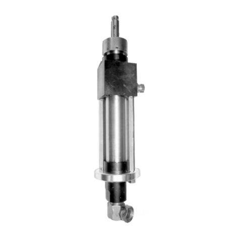
TAS 14 - Hi Flow Infusion Valve
Low Pressure 10Bar- Nylon Hose: # Assy-0437
Also available:
TAS 14 Spares Kit: Assy-0469
Procedure for set-up and use
The TAS 14 - Hi Flow Infusion Valve is designed to interface between Infusion and LRTM moulds, and
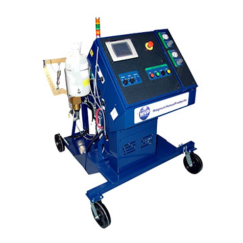
Magnum Venus Products meter mix machines, or any other automatic unit for dispensing mixed resin.
Rev. 08/2015

TAS 14 Instructions
Rev. 08/2015 Page | 3
To connect the Turbo Autosprue™ (TAS 14) to the mould, simply insert into one of the Universal Infusion
Inserts available from MVP and push firmly until the TAS 14 nose is flush with the insert’s front mould
face. To check the spring clip is locked, pull firmly and rotate the TAS body.
To remove the TAS 14 from the mould, release the spring clip, pull and rotate gold body 90 degrees.
Operation:
BEFORE USE:
Ensure that the inner surfaces of the TAS 14 Nose are well released. This should be repeated at
regular intervals to ensure that the sprue of cured resin does not stick to the aluminium nose.
With the TAS 14 firmly locked into the Universal Insert, connect the machine nozzle to the quick release
input connector. Connect the red 4mm start pipe to the 4mm banjo air fitting on the side of the TAS 14 body.
Place the 10mm nylon drain pipe in a vented waste container ensuring that it is firmly fastened in the
container to avoid the pipe becoming dislodged during flushing with solvent and air.
When the machine starts the TAS 14 valve will open (this is indicated by the small brass pin that is
showing above the black top cover) to allow free passage of resin mix into the mould. On completion of
the injection the machine will automatically close the TAS 14 nose, upon command, you can now flush
the mix-head, injection pipe and the internal fluid path of the TAS, with the waste solvent being delivered
to a vented waste container.
The TAS 14 is suitable for use in all orientations - vertical, upside down and horizontal, and exhaustive
tests have proven that the TAS 14 operates and flushes efficiently with a long service life in all positions
with all commonly used thermoset resin systems, whether filled or unfilled.

TAS 14 Instructions
Rev. 08/2015 Page | 4
All tests have been conducted using one of Magnum Venus Products injection machines fitted with the
SP3 or SP4 non-pressurised solvent pump system. In conditions of low air pressure (below 5.0 bar)
efficient flush and cleaning may not occur, leaving build up and traces of catalysed resin within the valve,
feed pipe and drain pipe. Ensure therefore that all flushing systems are maintained correctly and operated
at the recommended supply pressure range of 6 - 7 bar.
SAFETY NOTE:
Ensure that relevant Personal Protective Equipment, especially eye protection, is worn when testing or
servicing the TAS 14.
Note:
NEVER - Operate TAS 14 without sufficient cleaning/flushing solvent flow.
ENSURE –The correct cleaning/flushing solvent pressure of at least 6 bar
IMMEDIATELY - Renew nose outer red silicon seal (3265) if damaged
DO NOT - Unlock or attempt to remove TAS from the mould:
During the injection or flushing operation.
Until the resin in the mould has cured.
ONLY USE - Genuine TAS 14 spare parts from Magnum Venus Products.
RENEW –Universal clip if damaged or contaminated.
Maintenance:

TAS 14 Instructions
Rev. 08/2015 Page | 5

TAS 14 Instructions
Rev. 08/2015 Page | 6
MVP Ltd © 2010. Design rights MVP Ltd 2010 .World patents pending. Autosprue™
The TAS 14 is designed to operate for several hundred injection cycles without any
need for maintenance. After lengthy service (700-1200 cycles) we recommend that the
following maintenance checks are carried out.
1. TESTING THE SEALS.
Operate the valve between open and closed and check that the valve nose seal moves back and forward
by 7- 8mm. If the movement of the nose seal is observed to be sluggish proceed to check and if
necessary replace the main piston seal and / or the shaft seals.
2. CHANGING THE NOSE SEAL.
With the TAS closed (no open signal) operate the machine’s flush cycle.
After 12 seconds and with the air-dry flush cycle still operating block the drain pipe outlet. This will
pressurise the valve’s fluid section and enable the observation of any air leakage out through the main
nose seal # 6782.
Should any air leakage be present under these conditions replace the nose seal # 6782.
The integrity of the nose seal # 6782 is determined entirely by the tightness of the nose screw # 0299 as
it compresses the nose seal against the washer # 6059 and the base of the shaft.
CORRECT TIGHTENING of the nose screw will seal the nose.
OVER TIGHTENING of the nose screw will seal the nose BUT prevent the nose seal moving back and
forth between the seal surface of the nose # 6781 and the seal surface of the body # 6780.
UNDER TIGHTENING of the nose screw will not seal the nose and it may leak solvent and air into the
mould cavity and/or leak resin through to the flush outlet whilst injecting.
To achieve the correct tightening of the nose screw we recommend the following actions:
Assemble the nose seal # 6782 with the back-up washer # 6059 and the nose seal screw # 0299 as
shown using a small amount of BLUE LOCTITE 243 on the end of the screw. Screw into the shaft end #
5828 until it is finger tight and meets some resistance.
At this point proceed to turn the screw a further ¼ to ½ turn ensuring that the shaft # 5828 does not turn
at the same time. - To prevent the shaft from turning, apply 6 –7 bar air pressure to the small 4mm air
fitting # 0645 on the side of the main body. This will open the valve and hold the shaft tight.
Immediately reassemble the valve and connect to the machine, and with the TAS out of the mould
operate the flush cycle and observe that there is no leak of solvent, or air from the sealed nose.
To test the integrity of the nose seal, further pressure can be applied to the TAS by blocking the TAS
drain pipe whilst the machine is flushing, this action will place the nose seal under full shop air pressure.
NOTE: The flush line should only be blocked in this manner once the solvent has flushed through and the
valve is only purging with air pressure.
If any leakage is observed at the nose during this test, immediately tighten screw # 0299 by a further ¼
turn, or more until the leak is sealed. This will increase the diameter of the nose seal # 6782 a further
fraction of a millimetre and effectively seal the nose in both the closed and open conditions.
3. CHANGING THE PISTON SEAL & SHAFT SEALS.
The 2 main shaft seals # 6004 should be replaced every 2,000 cycles or sooner if required. Any resin found
to be migrating into the upper air cylinder indicates the need for the immediate renewal of seals # 6004.
These are accessed by first removing the nose seal # 6782, then unscrew the cylinder top (but be aware
of the force of the internal spring). The Spring, Limiter and Piston assembly is then withdrawn from the
open cylinder end by pulling on the end of the brass shaft.

TAS 14 Instructions
Rev. 08/2015 Page | 7
Problem Solving:
TAS Valve sticking
1. The heavy, and very sticky silicon grease (especially at low temperatures) that is used to lubricate
the air cylinder can if applied too liberally, form a seal between the base of the cylinder and the
underside of the piston. During times of rest the grease can form a perfect, but unwanted seal as it
is compressed by the spring.
oTo solve the problem,remove all traces of over greasing especially on the underside of
the aluminium piston and cleaning any grease from the bottom of the internal air cylinder.
The only grease needed is a very light smear on the vertical walls of the cylinder and a very
light smear on the two red o rings before replacing the piston assembly back into the
cylinder. Any additional grease will lead to re-appearance of the occasional problem of
sticking closed.
2. If the valve is still difficult to open, then check that:
oAt least 7 bar pressure is available to power the valve.
oThat the TAS valve been flushed correctly.
Damaged TAS Nose
1. It is most important not to damage the sealing surface of the 14mm hole in the TAS nose. Damage
usually occurs when the valve has been gelled up and mechanical attempts have been made to
rectify the problem.
oTo solve the problem clean the gelled up nose surface with solvent and a cloth, or
alternatively, leave the nose in acetone for several hours to soften the residue before
attempting to clean the internal surface of the nose. On no account should any hard metal,
or a 14mm drill bit, be used to scrape or clean this surface. The inner surface of the nose
MUST be released prior to and regularly during production use.
oNOTE: Any scratch, or pitting damage on the precision 14mm nose bore will result in a
leaking nose seal and eventual damage to the nose seal itself. In the event that this nose
seal surface is observed to be damaged as described then it is necessary to replace with a
new nose # 6781.
Table of contents
Other MVP Control Unit manuals
Popular Control Unit manuals by other brands

PAW
PAW HeatBloC K35 DN 25 Installation and operation instructions

stepRocker
stepRocker TMCM-1110 Hardware manual

Hydac
Hydac FCU 5000-T001 Installation and maintenance instructions

M-system
M-system R7M-DC4G instruction manual

Vestamatic
Vestamatic IF SMI KNX 24VDC Installation and operating instructions

Ergotron
Ergotron DM16-1004 manual