Waterous 500-100-P User manual

12/22/2011
Operation Guide
Applies to Waterous Model
500-100-P
500-120-P
Rev 1
Unit Serial Number ______________________
Waterous Arizona Operations
7612 North 74th Ave.
Glendale, Arizona 85303
623-979-3398
Fax: 623-979-6949
www.waterousco.com

Waterous Arizona Operations 500-100 & 120-P Operations Rev 1
Page 2 of 30
Warnings, Cautions, and Notes
Warning
A warning alerts you to a procedure, practice or condition that may result in death or long
term injury to personnel or destruction of equipment.
Caution
A caution alerts you to a procedure or condition that may result in serious
damage to equipment or its failure to operate as expected
Note: A note points out important information. Failure to read the note may not result in
physical harm to personnel or equipment. It may waste time and money.
Revision History
Revision
Date Issued
Comments
---
11/2005
Original Release
1
12/22/11
Reformat, new logo, updated pics, more
tables
Disclaimer: These instructions are guidelines only and in no way meant to be definitive. During installation, standard safety
precautions and equipment should be used where appropriate. Because the tools used and the skill/experience of the installer can
vary widely, it is impossible to anticipate all conditions under which this installation is made, or to provide cautions for all possible
hazards. Proper installation is the responsibility of the purchaser. All bolts, setscrews, and belts must be checked prior to start-up
AND after the initial operation. Damages due to poor installation are the responsibility of the installer.

Waterous Arizona Operations 500-100 & 120-P Operations Rev 1
Page 3 of 30
Table of Contents
SECTION 1. OPERATING INSTRUCTIONS.........................................................................................4
A. Multiple Uses.....................................................................................................................................4
B. For Electric Auto-Sync ......................................................................................................................4
I. Water Pumping Operations...........................................................................................................5
II. Foam Solution Operations ............................................................................................................5
III. Compressed Air Foam Operations................................................................................................5
IV. Compressed Air Only Operation ...................................................................................................6
C. Shut-Down Procedure.......................................................................................................................7
SECTION 2. COMPRESSOR ................................................................................................................8
A. How It Works.....................................................................................................................................8
SECTION 3. SYSTEM SERVICE AND MAINTENANCE.......................................................................9
A. Maintenance Schedule....................................................................................................................10
B. Maintenance Items..........................................................................................................................10
C. Wye Strainer for Cooler...................................................................................................................11
SECTION 4. CAFS NOZZLE / FLOW RATE / HOSE COMBINATIONS .............................................12
A. Nozzles............................................................................................................................................12
B. Foam Concentrate Ratios ...............................................................................................................12
C. Hose................................................................................................................................................12
SECTION 5. SUGGESTED GUIDELINES FOR THE PRODUCTION OF MID-RANGE
COMPRESSED AIR FOAM........................................................................................................................13
A. 1” (25 mm) Hose Diameter Jacketed..............................................................................................13
B. 1-1/2” (38 mm) Hose Diameter .......................................................................................................13
C. 1-3/4” (44 mm) Hose Diameter .......................................................................................................14
D. Master Stream.................................................................................................................................15
SECTION 6. TROUBLESHOOTING....................................................................................................16
A. CAFS...............................................................................................................................................16
B. Pump...............................................................................................................................................20
SECTION 7. CONDITIONAL 5-YEAR WARRANTY POLICY..............................................................30
Figure(s)
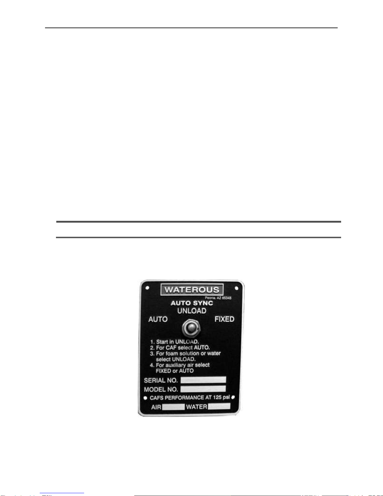
Figure 1 Electric Auto-sync panel ................................................................................................................4
Figure 2 Wye Strainer .................................................................................................................................11
Figure 3 Wye-strainer installed, with cleanout valve..................................................................................11
Figure 4 Clean Strainer..............................................................................................................................11
Figure 5 Dirty Strainer................................................................................................................................11
Figure 6 Basic CAFS Schematic................................................................................................................24
Figure 7 500-100-P Dimensions ...............................................................................................................25
Figure 8 Hydraulic Schematic....................................................................................................................26
Figure 9 Air Schematic, Electric Auto-sync, 90° inlet.................................................................................27
Figure 10 Electric Schematic, Auto-sync...................................................................................................28
Figure 11 Compressor Installation Angles.................................................................................................29

Waterous Arizona Operations 500-100 & 120-P Operations Rev 1
Page 4 of 30
SECTION 1. OPERATING INSTRUCTIONS
Check the following fluid levels daily or prior to operating system:
Compressor system oil (Oil level should be visible within the sight glass on the sump and
should be checked daily or before or after use.)
Foam concentrate
Onboard water supply
A. Multiple Uses
The Waterous compressed air foam unit can be operated in several pumping modes: water
only, foam solution without compressed air, compressed air foam, and compressed air only
for support operations such as operating air tools, filling rescue air bags, etc. It is possible to
pump foam solution from one discharge while pumping compressed air foam from another, or
varying foam consistencies (expansion ratios) from different discharges simultaneously.
NOTE: Monitor compressor instruments during any and all operations.
WARNING:
Prior to starting the engine, the Auto Sync controls should be in the UNLOAD position,
which allows the air compressor to “free wheel” without pumping air.
B. For Electric Auto-Sync
Figure 1 Electric Auto-sync panel

Waterous Arizona Operations 500-100 & 120-P Operations Rev 1
Page 5 of 30
I. Water Pumping Operations
All unit operations begin with pumping water. These steps must be followed for
operations involving pumping water, foam solution, compressed air or compressed
air foam.
1. Connect the hose(s) to the desired discharge(s).
2. If pumping water from an on board booster tank, fully open the tank to pump
valve.
3. If pumping from an overboard source, the tank to pump valve should be fully
closed.
4. Engage the PTO
5. If so equipped, turn on the main power switch to the CAFS unit.
6. Throttle-up to desired pressure.
If pump pressure is absent, it will be necessary to prime the pump.
7. Open desired discharge valve(s) and throttle-up to desired pressure.
CAUTION:
Running the unit with a dry fire pump can cause damage to the pump and
air compressor system.
II. Foam Solution Operations
Follow the instructions above for water pumping operations.
Turn on the foam proportioner to inject foam concentrate into the water stream. Refer
to the foam proportioner operation manual for instructions in the proper operation of
the installed proportioning system.
III. Compressed Air Foam Operations
Follow the instructions above for foam solution operations. Safe operations dictate
the presence of foam concentrate in the water stream prior to the injection of
compressed air. If foam concentrate is not present, a condition known as “slug flow”
will occur. This is where unmixed water and air is discharged through a nozzle in an
erratic manner.
1. Set water discharge pressure at the desired level.
Discharge pressures for compressed air foam operations typically range
between 80 and 120 PSI in a flow state.
NOTE: Compressed air foam does not have the hydraulic characteristics of plain
water or foam solution. Therefore, standard pump hydraulics practices do not
apply to CAFS operations.

Waterous Arizona Operations 500-100 & 120-P Operations Rev 1
Page 6 of 30
2. Move Auto-Sync controls to the AUTO position.
Air pressure as shown on the air pressure gauge should rise to within plus or
minus 5% of the water discharge pressure. The Auto-Sync system will
balance the air and water pressures throughout a range of 40 PSI up to 150
PSI. Optimal compressed air foam system performance occurs at discharge
flow pressures of 80-120 PSI.
3. Set proportioner at 0.2% - 0.6% for normal Class A combustibles.
The type and brand of foam concentrate used and the tactical objective,
dictate proportioning rates.
4. Open desired discharge valve(s).
Controlling the amount of foam solution entering the discharge stream sets
the foam expansion ratio. High solution flows restrict the amount of air
admitted and result in lower expansion or “wet” foam. To produce higher
expansion or “drier” foam, simply gate back the amount of solution admitted.
5. Fully open the air valve(s) to the desired discharge(s).
6. Adjust the solution flow to produce the desired foam consistency.
Foam is formed during the transition through the hose. To produce acceptable
finished foam, sufficient hose length must be provided on the discharge. Refer to the
section “Suggested Guidelines for the Production of Mid-Range Compressed Air
Foam”.
WARNING:
Nozzle reaction force is significantly increased at the time the nozzle valve is opened in
compressed air foam operations. OPEN CAFS NOZZLES SLOWLY!
IV.Compressed Air Only Operation
Follow instructions for water pumping operations without opening discharge valves.
Air compressor cooling is via water that is circulated by the fire pump through the
compressor cooler and returned back to the booster tank. During this operation, time
is limited by the amount of available cooling water.
The water in the booster tank will eventually become heat saturated and ineffective at
cooling the air compressor. Watch the compressor temperature gauge closely!
Maximum of 250°F. Compressor system overheat is also indicated by the panel
mounted warning light and alarm.
1. After PTO engagement, ensure that the water pressure as shown on the
panel mounted gauge rises.
2. Move Auto-Sync control to the FIXED position. Air pressure will rise to the
preset pressure setting on the air compressor, approximately 150-PSI with
the engine throttled-up.
3. For lower operating pressures, move the Auto-Sync controls to the AUTO
position and use the engine throttle to control the water pressure / air
pressure
4. Connect the air discharge hose to the fitting on the pump operator’s panel
and open the air supply valve.

Waterous Arizona Operations 500-100 & 120-P Operations Rev 1
Page 7 of 30
Extended compressed air only operations necessitate connection of an external
water source to the pump inlet and closing of the tank to pump valve far proper
compressor cooling. In this case, cooling water will flow into the booster tank at 10-
20 GPM, eventually overflowing the tank.
C. Shut-Down Procedure
Close air valve(s)
Turn off Foam proportioner
Flow clear water through discharge hose(s) until no bubbles are present
Close discharge valve(s)
Move Auto-sync controls to: Electric = UNLOAD
Shut system down
After the system is shut down, the compressor system will vent itself, creating an audible hiss
as compressed air is evacuated from the pressure vessel/sump.
WARNINGS
Compressed air can be dangerous. Read and understand the operating
instructions for the Waterous compressed air foam unit and individual components
prior to operating.
DO NOT use the compressed air foam unit as an air source for SCBA or any
breathing air supply.
Discharge outlets that are capped, hose lines that are valved and charged and the
air compressor sump may contain compressed air. Relieve all pressure BEFORE
attempting to remove any caps, fittings, and nozzles or to perform maintenance to
prevent serious personal injury.
Nozzle reaction force is significantly increased at the time the nozzle valve is
opened in compressed air foam operations. OPEN CAFS NOZZLES SLOWLY!
Operating the compressed air foam unit with water and compressed air pumped
through a discharge without foam concentrate will create a potentially dangerous
condition known as "Slug Flow"; where unmixed pockets of water and air are
passed through the nozzle, causing erratic nozzle reaction.
For compressed air foam operations, use only fire hose that is rated at 200 PSI or
higher working pressure.
The unit operator should have a thorough understanding of "Boyle's Law" (The
law of compressed gases) prior to operating the compressed air foam unit.

Waterous Arizona Operations 500-100 & 120-P Operations Rev 1
Page 8 of 30
SECTION 2. COMPRESSOR
A. How It Works
The air compressor used in this application is a GHH-RAND OS70, oil flooded rotary screw
type. Rotary screw air compressors are very common in industrial applications. This type of
compressor injects oil into itself, where it lubricates, seals, cools, and silences the
compressor. The oil is then entrained into the air discharge from the compressor. This air/oil
mixture is discharged into a sump tank where most of the oil separates from the air. The oil is
then sent via hydraulic hose to a combination cooler/thermostat/filter unit. It is cooled to
remove compression and friction heat, filtered, and sent to the oil injection port on the
compressor. The cycle is then repeated.
The oil mist that remains in the air stream is recovered by an air/oil separator system. This
system recovers the oil mist in a spin-on cartridge that has a siphon tube that picks up the
recovered oil for return to the air compressor.
A modulating inlet valve controls the compressor’s air output. The inlet valve is opened and
closed by the Auto Sync pressure control system.
The compressor cooling system circulates water from the fire pump through the compressor
oil cooler and back to the tank to remove heat from the compressor oil system. The
compressor oil temperature should not exceed 250°F. If this occurs, check the water supply;
pump prime, restrictions in the cooling water system and for low oil level in the sump.
The air compressor (air end) is mounted to the transmission of a Waterous CLVK single
stage pump and driven by a dry Poly Chain. The pump / air end are PTO driven by the
engine. It is important to ensure that there is a water supply to the pump whenever the
system is running. Pump and/or compressor damage may result from running the pump dry.

Waterous Arizona Operations 500-100 & 120-P Operations Rev 1
Page 9 of 30
SECTION 3. SYSTEM SERVICE AND MAINTENANCE
Excessive heat build-up and oil system contamination are most common causes of
compressor system problems and premature wear. With proper operation and maintenance,
the compressor system should far outlast the vehicle it is mounted on. Adherence to the
following guidelines will prevent potentially costly damage.
1. There is a sight gauge provided on the oil reservoir and visible through a hole on the
pump panel. The oil level should be at approximately halfway up the window. Cheek the
oil on level ground, prior to system start up. If the system has recently been run, wait 10
minutes after shutdown for the oil to stabilize before checking the oil level. The oil should
be checked daily or before or after every use. The compressor uses common hydraulic
oil. This oil is classified by an ISO standard as ISO 68 viscosity and is sold under various
trade names. Many are sold as in “anti wear” hydraulic oil and area available from auto
parts or lubricating oil suppliers.
2. The oil should be changed after the first 30 hours of system operation. After that, the oil
should be changed annually. There is a drain plug located at the bottom of the sump. The
oil fill cap is located on top of the unit.
3. Change the compressor system oil filter at the same time as the oil is changed. The spin-
on filter cartridge is a Mann-Hummel hydraulic oil filter.
4. Run the compressor for 2 minutes after changing the oil, then re-cheek the oil level and
add oil as necessary. DO NOT OVERFILL.
5. Visually inspect the compressor oil system weekly for signs of leaks. Check the air
compressor Poly Chain drive for proper tension and signs of wear monthly or more
frequently as dictated by the amount of use.
6. Proper tension on the Poly Chain is to a no slack setting or slightly loose (about 3/8” - If in
doubt, do not tighten the Poly Chain). A slightly loose Poly Chain is acceptable. An over-
tightened Poly Chain may cause equipment failure, and may void the product warranty.
7. Inspect the compressor air intake filter and clean or replace as necessary. The
environment in which the unit operates will determine the frequency of air filter service
and replacement. In any situation, replace no less frequently than yearly.
8. Replace the oil / air separator cartridge every 24 months, or if the unit’s oil consumption
suddenly increases. A sudden increase may be caused by a hole in the internal media of
the cartridge allowing oil to carry through and discharge with the compressed air.
9. Completely drain the water from the compressor oil cooler in cold weather to prevent
freeze damage.

Waterous Arizona Operations 500-100 & 120-P Operations Rev 1
Page 10 of 30
A. Maintenance Schedule
Check Oil
Level & for
Oil Leaks
Change
Compressor
Oil
Change
Oil
Filter
Change
Separator
Cartridge
Daily or After
Each Use
X
Annually
X
X
Every 24 Months
X
Refer to the Engine Manual for recommended engine maintenance.
B. Maintenance Items
COMPRESSOR
Part#
AIR FILTER:
CO85004(1)
2030042
SEPARATOR FILTER:
LB 1374/2(2)
0390092
HYDRAULIC FILTER:
WD 920(2)
2030058
HYDRAULIC OIL
ISOAUW68 Anti-Wear, Low-Foaming, Anti-Foaming
BELTS
Part#
POLY CHAIN:
8MGT-1000-36(3)
1030014
(1) = Donaldson (2) = Mann & Hummel (3) = Gates

Waterous Arizona Operations 500-100 & 120-P Operations Rev 1
Page 11 of 30
C. Wye Strainer for Cooler
A wye-strainer is provided to strain water before it enters the cooler's water inlet. The wye
strainer requires regular inspection, and should be in an easily accessible location for
inspection, removal, and cleaning.
Caution:
Waterous is not responsible for damage due to plugged strainers. If the
customer's water system contains excessive debris, or the vehicle relies on
drafting for its water supply, it may be necessary to install a larger strainer
and/or a clean-out valve on the wye-strainer.
Without good water flow through the heat exchanger, the compressor will overheat.
Compressor performance will be inadequate, and it may fail completely.
Omitting the Wye-strainer or removing the screen from the Wye does not improve water
flow. It will allow debris into the cooler, which can clog the tiny heat exchanger tubes and
restrict water flow.
Figure 2 Wye Strainer
Figure 3 Wye-strainer installed, with
cleanout valve.
Figure 4 Clean Strainer
Figure 5 Dirty Strainer

Waterous Arizona Operations 500-100 & 120-P Operations Rev 1
Page 12 of 30
SECTION 4. CAFS NOZZLE / FLOW RATE / HOSE
COMBINATIONS
A. Nozzles
Compressed air foam can be discharged through various types and sizes of nozzles. Fog
nozzles breakdown the bubble structure of the foam. This results in “wetter” or reduced
expansion foam. The preferred way to make foam is utilizing smooth bore nozzles with a
given hose diameter. Smaller tips will discharge "wetter" foam.
B. Foam Concentrate Ratios
Proportioner settings of 0.2% and 0.6% are typically adequate to produce compressed air
foam that is formed in a hose line and used on Class A combustibles. Higher settings will
result in “drier” appearing foam. Lower settings may result in “slug flow” or discharge
pulsation caused by insufficient foam concentrate in solution to form foam in the hose line.
For Class B or other type foam ratio settings, follow the instructions provided by the foam
concentrate manufacturer.
C. Hose
Utilize fire hose that is rated by the hose manufacturer for use with CAFS. Since the foam is
formed during its transition through the hose line, it is important to utilize the minimum
recommended hose lengths, unless a static mixer is utilized. There is significantly less friction
and head loss with compressed air foam as compared to water or foam solution. Hence,
effective fire streams can be achieved with longer hose layouts. Refer to the Suggested
Guidelines for the Production of Mid-Range Compressed Air Foam.
NOTE: Compressed air foam systems have the ability to produce foam of shaving cream
consistency. While this type of foam is highly stable and possesses a long drain time,
it is essential to ensure that the foam will release sufficient water to extinguish a fire
in a direct attack situation. This type of foam is typically suited for defensive
operations such as exposure protection, barriers or fuels pretreatment.

Waterous Arizona Operations 500-100 & 120-P Operations Rev 1
Page 13 of 30
SECTION 5. SUGGESTED GUIDELINES FOR THE
PRODUCTION OF MID-RANGE COMPRESSED AIR
FOAM
A. 1” (25 mm) Hose Diameter Jacketed
1 GPM to 1 CFM
½” Tip Solution Flow: 15 GPM (56.78 LPM)
Air Flow: 15 CFM (0.42 m3/min)
Disch. Pressure: 100-150 PSI (6.804 - 10.206 BAR) (689.5 - 1034.25 KPA)
Min/Max Hose Length: 35’ to over 400’ (10.668 – 121.92 meters)
2 GPM to 1 CFM
½” Tip Solution Flow: 30 GPM (113.56 LPM)
Air Flow 15 CFM (0.42 m3/min)
Disch. Pressure: 100-150 PSI (6.804 - 10.206 BAR) (689.5 - 1034.25 KPA)
Min/Max Hose Length: 35’ to over 400’ (10.668 – 121.92 meters)
1 GPM to 1 CFM
¾” Tip Solution Flow: 20 GPM (75.71 LPM)
Air Flow: 20 CFM (0.56 m3/min)
Disch. Pressure: 100-150 PSI (6.804 - 10.206 BAR) (689.5 - 1034.25 KPA)
Min/Max Hose Length: 35’ to over 200’ (10.668 – 60.96 meters)
2 GPM to 1 CFM
¾” Tip Solution Flow: 40 GPM (151.41 LPM)
Air Flow: 20 CFM (0.56 m3/min)
Disch. Pressure: 100-150 PSI (6.804 - 10.206 BAR) (689.5 - 1034.25 KPA)
Min/Max Hose Length:35’ to over 200’ (10.668 – 60.96 meters)
B. 1-1/2” (38 mm) Hose Diameter
1 GPM to 1 CFM
1” Tip Solution Flow: 30-40 GPM (113.56 –151.41 LPM)
Air Flow: 30-40CFM (0.84 –1.12 m3/min)
Disch. Pressure: 100-150 PSI (6.804 - 10.206 BAR) (689.5 - 1034.25 KPA)
Min/Max Hose Length: 100’ to over 800’ (30.48 – 243.84 meters)

Waterous Arizona Operations 500-100 & 120-P Operations Rev 1
Page 14 of 30
2 GPM to 1 CFM
1” Tip Solution Flow: 60-80 GPM (227.12 –302.82 LPM)
Air Flow: 30-40CFM (0.84 –1.12 m3/min)
Disch. Pressure: 100-150 PSI (6.804 - 10.206 BAR) (689.5 - 1034.25 KPA)
Min/Max Hose Length: 100’ to over 800’ (30.48 – 243.84 meters)
1 GPM to 1 CFM
1-3/8” Tip Solution Flow: 50-60 GPM (189.27 –227.12 LPM)
Air Flow: 50-60 CFM (1.4 –1.68 m3/min)
Disch. Pressure: 100-150 PSI (6.804 - 10.206 BAR) (689.5 - 1034.25 KPA)
Min/Max Hose Length: 100’ to over 800’ (30.48 – 243.84 meters)
2 GPM to 1 CFM
1-3/8” Tip Solution Flow: 90-120 GPM (340.68 –454.24 LPM)
Air Flow: 50-60 CFM (1.4 –1.68 m3/min)
Disch. Pressure: 100-150 PSI (6.804 - 10.206 BAR) (689.5 - 1034.25 KPA)
Min/Max Hose Length: 100’ to over 800’(30.48 – 243.84 meters)
C. 1-3/4” (44 mm) Hose Diameter
1 GPM to 1 CFM
1” Tip Solution Flow: 30-40 GPM (113.56 –151.41 LPM)
Air Flow: 30-40 CFM (0.84 –1.12 m3/min)
Disch. Pressure: 100-150 PSI (6.804 - 10.206 BAR) (689.5 - 1034.25 KPA)
Min/Max Hose Length: 100’ to over 1400’ (30.48 – 426.72 meters)
2 GPM to 1 CFM
1” Tip Solution Flow: 60-90 GPM (227.12 –340.68 LPM)
Air Flow: 30-50 CFM (0.84 –1.4 m3/min)
Disch. Pressure: 100-150 PSI (6.804 - 10.206 BAR) (689.5 - 1034.25 KPA)
Min/Max Hose length: 100’ to over 1400’ (30.48 – 426.72 meters)
1-3/8” Tip Solution Flow: 50-90 GPM (189.27 –340.68 LPM)
Air Flow: 50-80 CFM (1.4 –2.24 m3/min)
Disch. Pressure: 110-150 PSI ( 7.4844- 10.206 BAR) (758.45- 1034.25 KPA)
Min/Max Hose Length: 100’ to over 700’ (30.48 – 213.36 meters)

Waterous Arizona Operations 500-100 & 120-P Operations Rev 1
Page 15 of 30
NOTE: With 1-3/4” hose lengths of 100’-250’ (30.48 –76.2 meters), up to 90-120 GPM (340.68 –
454.24 LPM) of water and 40-100 CFM (1.12 –2.8 m3/min)of air may be utilized as a
highly effective initial attack flow.
System flows are very flexible. The flow of any discharge can vary according to the situation
and conditions.
It is possible to make the discharge stream wetter or drier by changing the amount of solution
or air in the hose.
The stream can also vary by changing the tip size at the nozzle.
The bigger the diameter tip, the drier the foam.
The smaller the diameter tip, the wetter the foam.
D. Master Stream
1” Tip Solution Flow:
90-120 GPM (340.68 –454.24 LPM)
Air Flow: 60-80 CFM (1.68 –2.24 m3/min)
1-3/8” Tip Solution Flow:
100-150 GPM (378.53 –567.80 LPM)
Air Flow: 70-100 CFM (1.96 –2.8 m3/min)
1-1/2” Tip Solution Flow:
120-200 GPM (454.24 –757.06 LPM)
Air Flow: 80-120 CFM (1.68 –3.36 m3/min)
1-3/4” Tip Solution Flow:
180-250 GPM (681.35 –946.33 LPM)
Air Flow: 120-150 CFM (3.36 –4.2 m3/min)
2” Tip Solution Flow:
250-450 GPM (946.33 –1703.39 LPM)
Air Flow: 200 CFM (5.6 m3/min)
Disch. Pressure: 120-150 PSI (8.1648 –10.206 BAR) (827.4 –1034.25 KPA)

Waterous Arizona Operations 500-100 & 120-P Operations Rev 1
Page 16 of 30
SECTION 6. TROUBLESHOOTING
A. CAFS
Observed
Symptom
Probable Cause
Suggested Remedy
Lack of air pressure
from compressor
Lack of air supply to
clutch (for air-clutch
systems)
Repair air leak or re-establish air supply
Compressor not
engaging
No PTO engagement
Confirm OK TO PUMP light is on, if not check wiring for damage or
disconnected wire, check PTO.
Compressor
engaging. No air
supply to
discharges or
insufficient air
supply.
Auto-Sync switches not
in correct position.
Confirm 40 PSI in UNLOAD position (200 CFM systems) and 50+ in run
position.
Smaller compressors have lower UNLOAD pressures.
Verify when in FIXED/RUN whether pressure reflects 145-150 PSI
(electric valves) Verify
there is power to the air
solenoid and check
operation of solenoid.
Air discharge solenoid not working.
Repair/replace solenoid
Air solenoid working - leak between solenoid and discharge. Repair leak.
Air check valve defective
Replace or correct installation.
Trim valve out of
adjustment
Refer to trim valve instructions
Restricted minimum
pressure valve
Clean rust or debris from valve
Air plumbed before
discharge valve seal
Relocate to discharge side of discharge valve
Incorrect air line size
Size according to discharge and replace line with correct size.
System functioning
correctly, pressure
gauge reading
obviously incorrect.
Gauge malfunction, air
line detached
Check for air leaks, replace gauge
FIXED has
pressure but AUTO
has
no pressure
No water supply to
balance valve.
Check line for proper installation, with no kinks or obstructions.
Refer to trim valve instructions.
Air discharge
pressure too high
Red hose circuit
(compressed air control)
has leak or is
disconnected.
Repair leak or attach hose

Waterous Arizona Operations 500-100 & 120-P Operations Rev 1
Page 17 of 30
Observed
Symptom
Probable Cause
Suggested Remedy
System overheating
Inadequate water flow
through cooler
Ensure adequate water flow through pump. Check Y strainer for
obstruction, clean and reinstall Drain and flush cooler water tubes
Adequate water flow
through cooler.
On-board tank used for cooling for a prolonged period - water too hot to
effectively cool the compressor. Locate source of lower temperature water.
Check oil level -
Adjust level to half of the sight glass on level surface.
Low compressor oil
level:
Check the hydraulic lines for kinks
Change oil filters
Temperature sending
unit and or gauge circuit
malfunction.
Check wire connections at sending unit
High Oil
Consumption
Overfull compressor oil
Adjust level to half of the sight glass on level surface.
Excess of 200 CFM air
flow (on 200 CFM
systems)
Back down RPM's and flow CAFS to relieve pressure, then recheck
Replace Air/Oil Separator Filter
Air/oil Separator Filter
torn or damaged (could
be caused by air flow of
higher than 200CFM)
System being operated at higher than capacity
"Excessive"
compressor bleed
down time on
shutoff
Systems vary in bleed
down time.
If Auto-Sync is operating correctly, and compressor output is within spec,
do nothing.
Engine stalls upon
compressor
engagement
Engaging compressor
while under load
Allow compressor to bleed down before re-engagement
Running system without
flowing air causes oil to
accumulate in
compressor acting like
hydraulic pump
Bleed down air, restart compressor, and move air
Underrated engine
horsepower
Raise engine RPM
Auto-Sync in FIXED /
RUN setting
Engage in AUTO/UNLOAD, then switch to FIXED/RUN
High oil level
Check oil level, adjust level to half of the sight glass with vehicle parked on
a level surface
Compressor locked up
Repair/replace compressor

Waterous Arizona Operations 500-100 & 120-P Operations Rev 1
Page 18 of 30
Observed
Symptom
Probable Cause
Suggested Remedy
Compressor locked
up
High oil level
(compressor is flooded)
Check oil level, adjust level to half of the sight glass with vehicle parked on
a level surface
Sump fire
Check system and repair
Low oil level or no oil
Check system and repair
Air flow meter stuck
at "0" CFM
Magnet uncoupled in
meter
Turn air flow on and off to re-couple
Air flow meter stuck
at high CFM
Move large amounts of air out discharge and turn air flow on and off to re-
couple
Poor foam (wet or
dry) or no foam
(assuming air
pressure to
discharges is OK)
Using wetting agent and
not foam concentrate.
Use foam concentrate
Foam proportioning
control turned too low.
Increase amount of concentrate delivered to manufacturer recommended
amount.
Foam proportioning
control OFF or turned
too low, foam tank
empty.
Make sure proportioner is turned on, foam supply valve is open, foam tank
has concentrate, Y strainer is clean, and supply line is connected to
injector.
Discharge hose
shaking (slug flow)
Foam proportioner ON,
setting correct, and tank
has foam concentrate,
but not providing foam
solution.
Refer to foam proportioner manufacturer's instructions for detailed
calibration and troubleshooting instructions
Foam in the water
system (when
proportioner turned
off)
Foam concentrate was
poured into the on-board
water tank
Flush tank and pump with clean water, refill
Foam manifold drain
lines not isolated from
water drain lines
Isolate to separate drain valve
Cooler line plumbed
from foam manifold
Relocate line to discharge side of pump
Foam manifold check
valve defective
Rebuild/replace check valve
Water in
compressor oil/air
Leaking inside cooler
Freeze damage
Isolate cooler and check for leaks, replace if needed, check drain
Defective air check
valves
Replace or check
Missing air check valves
for discharges
Install check valves

Waterous Arizona Operations 500-100 & 120-P Operations Rev 1
Page 19 of 30
Observed
Symptom
Probable Cause
Suggested Remedy
Clutch smoking
Engaging in RUN
position
Engage in AUTO/UNLOAD only
Slight air leak from
solenoid to clutch
Repair air leak
High RPM engagement
Engage in lower RPM
Not allowing compressor
to bleed down before
engaging clutch again
Allow for bleed down
Contaminated clutch
disc
Clean or replace
Safety pop off valve
opening at low
pressure
Auto-Sync system out of
balance
Adjust the Auto-Sync system, making sure to not open the trim valve on
the compressor more than 3 turns.
Sump fire damaged pop
off valve
Check system for other damage and replace valve
Safety pop off valve
repeatedly opening
Trim valve or inlet
completely open
Refer to trim valve instructions

Waterous Arizona Operations 500-100 & 120-P Operations Rev 1
Page 20 of 30
B. Pump
Observed
Symptom
Probable
Cause
Suggested Remedy
Pump fails to prime or
loses prime
Air leaks
Clean and tighten all Intake connections. Make sure intake hoses and
gaskets are in good condition.
Use the following procedure to locate air leaks:
1. Connect Intake hose to pump and attach Intake cap to end of hose.
2. Close all pump openings.
3. Open priming valve and operate primer until vacuum gage Indicates 22
in. Hg/.735 atmospheres. (If primer fails to draw specified vacuum, it may
be defective, or leaks are too large for primer to handle.)
4. Close priming valve and shut off primer. If vacuum drops more than 10
in. Hg/.334 atmospheres In 5 minutes, serious air leaks are indicated.
With engine stopped, air leaks are frequently audible. If leaks cannot be
heard, apply engine oil to suspected points and watch for break in film or
oil being drawn into pump.
1. Completely fill water tank (if so equipped).
2. Connect intake hose to hydrant or auxiliary pump.
3. Open one discharge valve and run in water until pump is completely
filled and all air is expelled.
4. Close discharge valve, apply pressure to system and watch for leaks
or overflowing water tank. A pressure of 100 psi is sufficient.
DO NOT EXCEED RECOMMENDED PRESSURE.
1. If pump has not been operated for several weeks, packing may be
dried out.
2. Close discharge and drain valves and cap intake openings.
3. Operate primer to build up a strong vacuum In pump.
4. Run pump slowly and apply oil to Impeller shaft near packing gland.
5. Make sure packing is adjusted properly.
Dirt on Intake strainer
Remove all leaves, dirt and other foreign material from Intake strainer.
When drafting from shallow water source with mud, sand or gravel bottom,
protect intake strainer In one of the following ways:
1 Suspend Intake strainer from a log or other floating object to keep It off
the bottom. Anchor float to prevent it from drifting Into shallow water.
2. Remove top from a clean barrel. Sink barrel so open end is below water
surface. Place Intake strainer Inside barrel.
3. Make an Intake box, using fine mesh screen. Suspend intake strainer
Inside box.
No oil In priming tank
With rotary primer, oil is required to maintain a tight rotor seal.
Check priming tank oil supply and replenish, if necessary.
This manual suits for next models
1
Table of contents
Other Waterous Control Unit manuals
Popular Control Unit manuals by other brands

Camozzi
Camozzi K8B Series Use and Maintenance Instruction

resideo
resideo Braukmann D05FT installation instructions

Chauvet
Chauvet Epix Drive 642 Quick reference guide

ABB
ABB Relion 611 Series quick start guide

Feig Electronic
Feig Electronic cVEND plug Installation

Wheelock
Wheelock MZC-RM installation instructions