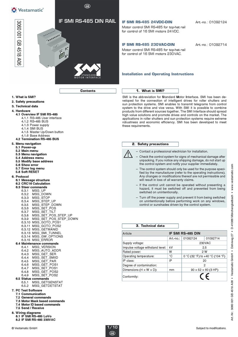
Vestamatic IF SMI KNX 24VDC User manual

Art.-Nr.: 84501110 E1 • Vestamatic GmbH • Dohrweg 27 • D-41066 Mönchengladbach • www.vestamatic.com
Subject to modifications.© by Vestamatic GmbH
IF SMI KNX
24VDC
Art.-no.:
01092510 Installation and Operating Instructions
IF SMI KNX 24VDC Art.-no.: 01092510
Intelligent motor control for 8 SMI LoVo motors.
Option of connecting up to 8 SMI LoVo 24VDC motors to
control interior blinds and interior motors
Compatible with KNX BUS system
Programmable button and LED for addressing indication on the device
KNX objects, Up/Down, Step/Stop, shading position, automatic
Shutter height %, slat %, shutter height status %, slat status %
Store/Call up scene 1+2, drive status
Individual and group control via KNX output devices
(conform EIS7 Standard or DPT 1.007 and 1.008 described in KNX
System Specifications Interworking Datapoint Types)
Fully synchronised operation of shades also possible in parallel
connection
Short description
Technical data
1/ 15
G
Safety precautions
–Contact a professional electrician for installation.
–Check the control system for signs of mechanical damage after
unpacking. If you notice any shipping damage, do not start up
the control system and notify your supplier immediately.
–The control system should only be used for the purpose speci-
fied by the manufacturer (refer to the operating instructions).
Any changes or modifications thereof are not permissible and
will result in loss of all warranty claims.
–If the control unit cannot be operated without presenting a
hazard, it must be switched off and prevented from being
switched on unintentionally.
– Turn off the power supply and prevent it from being switched
on unintentionally before performing work on any windows,
control or sunshades driven by the control system.
Ä
Supply voltage: 24VDC
Housing: REG 2TE
Interface for BUS system: KNX, Medium TP1
Interface for motor:SMI
Communication projects: 82
Max. number of group addresses: 114
Max. assignment of group addresses: 162
Operating temperature: 0°C (32 °F) to +40 °C (104 °F)
Software class: A
IP class: IP 20
Degree of contamination: 2
Dimensions (L × W × D): 90 × 35 × 59 mm
Mark of conformity: p
Notes for professional electricians
1. Connect the control in accordance with the wiring diagram.
2. Attach module on the top-hat rail and push until the module audibly clicks
into place on the mounting rail.
Installation
Wiring diagram

© Vestamatic GmbH
Art.-Nr.: 84501110 E1 • Vestamatic GmbH • Dohrweg 27 • D-41066 Mönchengladbach • www.vestamatic.com
IF SMI KNX 24VDC
Subject to modifications.
Contents General functional description
What is SMI? 17
General functional description 17
Software and functions 17
Operating states 18
State administration and state table 18
Travel command lock18
Safety 18
Manual mode 18
Automatic mode 18
State table 19
ETS interface 20
ETS communication objects 21
“Safety” object 22
“Travel command lock” object 22
“Up/Down travel, channel x” object (manual mode) 22
“Stop/Step travel, channel x” object (manual mode) 22
“Sunshade, channel x” object (automatic mode) 22
“Automatic mode, channel x” object 22
“Position of sunshade (%), channel x” object
(automatic mode or, if automatic deactivated, manual mode) 22
“Position of slat angle (%), channel x” object
(automatic mode or, if automatic deactivated, manual mode –
only for blinds) 22
“Status position of sunshade (%), channel x” object 22
“Status position of slat angle (%), channel x” object
(only for blinds) 23
“Move to scene pos1/pos2, channel x” object
(manual mode) 22
“Save scene pos1/pos2, channel x” object (manual mode) 23
“Drive error status” object 23
ETS parameters23–27
Planning and activation 27
Initialisation using drives with slave addresses already
programmed 27
Initialisation using drives with non-programmed slave
addresses or slave address 0 27
Errors and warnings during initialisation 28
Procedure for planning and activation 28
Options in the case of errors during planning and activation 28
User interface objects and properties (UIO interface) 28
Errors and warnings in properties 201 & 202
in the device object 28
User interface object 50001 and properties therein 29
Property 1, 51, 64 and 65 h 29
Property 80, 81 to 88 30
The SMI software 30
SMIdrive 8 is an EIB actuator for the control of up to 8 SMI drives.The
drives are independently addressed and controlled via the SMI.The drives
are controlled depending on the parametrisation of the actuator and com-
mands received via the EIB.Commands and data are transmitted via the
EIB using communication objects.Thus the drives connected to the actua-
tor can be moved independently via the EIB using standard functions such
as up/down, step/stop and others.Also, status information such as current
shade or slat position (%) and motor errors can be interrogated via the
EIB.A determination of prioritised operating states integrates manual and
automatic operations as well as those controlled by safety monitors or travel
locks.
The parametrisation and activation of the device is carried out via the ETS.
The ETS interface presents the project manager with parameters ar-
ranged in tabs.The communication objects are tabulated. The addressing
of the SMI drives connected to the device is carried out via the ETS acti-
vation. The addressing of the drives on the SMI side is either carried out
automatically using the slave addresses assigned in the ETS parametri-
sation or alternatively using SMI key IDs given in the ETS.
On the SMI side, the actuator only uses commands from the SMI standard
and is thereby compatible with SMI drives from all manufacturers.The
actuator does not functionally support use of manufacturer-specific fea-
tures.Nevertheless, manufacturer-specific parametrisation of SMI drives
can also be carried out via the EIB (see following section).
In addition to ETS parametrisation, a UIO (user interface object) interface
can be used in order to obtain access to the internal actuator SMI con-
figuration or directly to the SMI communication via the EIB.Software is
available for the practical use of this interface.It is, however, in principle
also possible to use this interface with, for instance, the device editor from
the ETS3 packet. The UIO interface permits further diagnostics within the
context of activation and also subsequent interventions in the parametri-
sation of SMI drives themselves.
Software and functions
The software of the SMI actuator consists of different units, which divide
into the resources available in the actuator hardware (a processor with
integrated Flash ROM, RAM and additional EEPROM).
The EIB operating system of the actuator “System 2” is compatible with
the BCU2 standard. It provides the entire interface for hardware resources
and applications software (firmware) on the one hand and for EIB on
the other.A bootloader in the Flash-ROM of the processor is an integral
component of System 2 and permits an exchange of software parts,
especially firmware (this is the applications software including SMI
communications library) through access via the EIB.The firmware is
mirrored in a copy in the EEPROM. Only firmware recognised as valid
is copied by the bootloader from the EEPROM into the processor Flash
ROM and, if appropriate, implemented.
An SMI communications library is an integral component of the firm-
ware.It is certified on the part of SMI and constitutes the interface to
the SMI and the slaves connected to it.
The actual applications software uses the remaining actuator memory
for the actuator software functionality depending on ETS parametrisa-
tion. It also includes the operation of the UIO interface via standardised
system functions.
The ETS interface includes information on EIB communication objects
and parameters, which specify the interface with the EIB and the
functionality of the actuator.These elements can be configured and
loaded into the actuator using the ETS.This information thereby reaches
the EEPROM of the actuator and can be read there by the operating
system and by the firmware and be evaluated in detail to determine the
performance.
Different software tools permit access to specific memories of the actuator
via the EIB.In addition to standard development tools, these tools are
namely a firmware update tool, which under certain conditions permits an
update of the firmware via the EIB, as well as an SMI tool, which using the
UIO interface supports diagnoses and direct access to the SMI via a gate-
way.
The functionality of the firmware and the elements of the ETS surface are
firstly described below. Other sections will explain specifics on the activa-
tion and the UIO interface.
2/ 15
G
SMI is the abbreviation for Standard Motor Interface.SMI has been de-
veloped for the connection of intelligent drives for roller shutters and sun
protection systems.SMI enables to transmit telegrams from control
system to the drive and vice versa. With SMI it is possible to combine
products from different sources together.The SMI Interface should spread
high value solutions and promote drives and controls on the market. The
applications in roller shutters and sun protection systems require extreme
robustness and economic efficiency.SMI has been developed to meet
these requirements.
What is SMI?

Subject to modifications.© Vestamatic GmbH
Art.-Nr.: 84501110 E1 • Vestamatic GmbH • Dohrweg 27 • D-41066 Mönchengladbach • www.vestamatic.com
IF SMI KNX 24VDC
State administration and state table
The actuator basically distinguishes between the following states (in order
of decreasing priority):
1) Travel command lock
2) Safety
3) Manual mode
4) Automatic mode
The automatic mode can be locked separately for each channel per ETS
parameter.In this case, the communication objects for switching between
automatic and manual mode and the sunshade objects do not appear.The
objects for positioning shade height and slat angle (%) are considered as
manual mode objects for all those channels for which the automatic mode
is locked; otherwise, they are considered as automatic objects.
The last state, which exists before a disconnection of the (EIB) bus voltage,
is restored when the bus voltage is switched back on.
Travel command lock
This state has the highest priority.It prevents all other movements, even
those due to a safety object. The purpose of setting a travel command lock
is, for example, to protect people who carry out work on automatically
moveable shades (window cleaners).
By activating the travel command lock, any ongoing movement of the
shade is still followed through; any movement-triggering telegrams that
arrive thereafter are no longer executed however.
As long as the travel command lock is active, one of the other states is
“masked” active in the background. By lifting the travel command lock, the
“masked” state is restored and in case of safety or automatic mode the
corresponding movement is also activated if appropriate.The “masked”
state is either the last one that existed before activation of the travel com-
mand lock or one which was observed by an interim telegram in the back-
ground.
If when activating the travel command lock, the actuator is, for example, in
automatic mode, incoming automatic travel commands are also stored
during the travel command lock and executed after it is lifted. If a safety
object with a “1” value occurs during the travel command lock, the
“masked” state changes into “Safety” and results in the corresponding
movement as soon as the travel command lock is lifted.
Manual mode commands, which occur during a travel command lock, are
ignored and do not result in a “masked” change in state either.
Safety
This state has the second highest priority.If a safety object with a “1” value
occurs, the state of the actuator changes into “Safety” mode (in the event
of existing travel command lock of the “masked” state). If there is no travel
command lock, the drive moves to the respective channel’s parametrised
position for this case.The purpose of the “Safety” state is to protect the
shades against wind that is too strong, for example.
By activating the safety function, any ongoing movement of the shade is
interrupted and any incoming movement-triggering telegrams are no longer
executed.
As long as the safety mode is active, one of the automatic or manual mode
states is “masked” active in the background. By lifting the safety state, the
“masked” state is restored and in case of automatic mode the correspond-
ing movement is also activated if appropriate.The “masked” state is the
last one which existed before activation of the safety function.
Automatic travel commands, which occur in the safety state, are observed
and only executed if safety mode and potentially command lock or manual
mode are overridden.
Manual mode commands, which occur while in a “Safety” state, are ignored
and do not result in a “masked” change in state either.
For those channels for which the automatic mode was deactivated per
parameter, an additional parameter can be set for each channel. This
parameter can determine that even those positions, which were specified
by manual mode-% objects, are restored, after the safety function is dis-
continued, to how they were before the safety function, or to how they
were preset in the “masked” state while the safety function was still active.
In the state table on the next page, reference is made to this information
in the “Safety off in manual mode without travel lock” field.The correspond-
ing parameter appears in the parameter description.
If the actuator receives a telegram to activate the travel command lock
while the safety function is active, the state switches to travel command
lock and the “Safety” state is “masked”.
Manual mode
This state has the third highest priority.Unless prevented by the travel
command lock or safety function, manual commands are executed imme-
diately and also result in a change in state in manual mode in the case of
existing automatic mode.A change of manual mode to automatic mode
can only be carried out using the automatic object with the value “1”.
Automatic mode
This state has the lowest priority. Automatic travel commands are only exe-
cuted in automatic mode.
3/ 15
G
Operating states

© Vestamatic GmbH
Art.-Nr.: 84501110 E1 • Vestamatic GmbH • Dohrweg 27 • D-41066 Mönchengladbach • www.vestamatic.com
IF SMI KNX 24VDC
Subject to modifications.
State table
The following state table reproduces the transitions between the operating states depending on events occurring (telegrams).
The manual mode state exists if all other operating states (automatic, safety and travel lock) are switched off.
4/ 15
G
No. Travel
lock
Safety
Auto-
matic
EIB
OFF
EIB
ON
Travel lock
ON
object
Travel lock
OFF
object
Safety ON
object or
time
monitoring
“Safety”
object
OFF
“Automatic”
object
ON
“Automatic”
object
OFF
“Manual
mode”
object
UP/DOWN
“Manual
mode”
object
Step
UP/DOWN
Move
to scene
object
Save
scene
object
(motor
stands)
Shade/slat
% position
object
Up/sun-
shade
object
(see note)
0off off off
0
Move to
position for
Bus OFF
0 4
Bring
current
movement
to end
0 2
Move to
safety
position
0 1
Move to
stored
shade/
slat position
0 0
Up and
down
0
Step up
and down
0
Move to
scene
0
Save scene
0
Setpoint
position is
only stored
0
Setpoint
position is
only stored
1off off on
1
Move to
position for
Bus OFF
1
Move to
stored
shade/slat
position
5
Bring
current
movement
to end
1 3
Move to
safety
position
1 1 0 0
Up and
down
0
Step up
and down
0
Move to
scene
1
Save scene
1
Movement to
and storage
of setpoint
position
1
Movement to
and storage
of setpoint
position
2off on off
2
Move to
position for
Bus OFF
2
Move to
safety
position
6
Bring
current
movement
to end
2 2 0
See comment
re.safety
operating
states
3 2 2 2 2 2
Save scene
2
Setpoint
position is
only stored
2
Setpoint
position is
only stored
3off on on
3
Move to
position for
Bus OFF
3
Move to
safety
position
7
Bring
current
movement
to end
3 3 1
Move to
stored
shade/
slat position
3 2 2 2 2 3
Save scene
3
Setpoint
position is
only stored
3
Setpoint
position is
only stored
4on off off
4 4 4 0 6 4 5 4 4 4 4 4
Save scene
4
Setpoint
position is
only stored
4
Setpoint
position is
only stored
5on off on
5 5 5 1
Move to
stored
shade/
slat position
7 5 5 4 4 4 4 5
Save scene
5
Setpoint
position is
only stored
5
Setpoint
position is
only stored
6on on off
6 6 6 2
Move to
safety
position
6 4 7 6 6 6 6 6
Save scene
6
Setpoint
position is
only stored
6
Setpoint
position is
only stored
7on on on
7 7 7 3
Move to
safety
position
7 5 7 6666 7
Save scene
7
Setpoint
position is
only stored
7
Setpoint
position is
only stored
Operating state Events

© Vestamatic GmbH
Art.-Nr.: 84501110 E1 • Vestamatic GmbH • Dohrweg 27 • D-41066 Mönchengladbach • www.vestamatic.com
IF SMI KNX 24VDC
Subject to modifications.
5/ 15
G
In the case of common parametrisation for all channels (“all equal”), one
tab each for the administration and the mechanics of the channels is
shown. Settings on these tabs are active for all channels and drives at the
same time.With individual parametrisation, one tab with administration
parameters, one with mechanical parameters and the communication
objects available for this channel depending on the setting are shown
respectively for each channel selected as “used”.
Depending on the addressing mode set on the general tab, either a tab for
setting only the slave addresses appears (in the case of “automatic”
addressing) or two other tabs for registering the manufacturer and the key
IDs of the drives used (in the case of “per manufacturer and SMI key ID”
addressing).
For those lists of communication objects and parameters reproduced as
follows, reference is made in the “Dependent on” column as to which other
settings the appearance of the respective element is dependent on.
Special reference is, however, no longer made in detail to the basic depen-
dency that channel-specific objects only appear for activated channels.
Fig. ETS interface
ETS2, two channels activated,
individual parametrisation,
automatic addressing.
ETS interface
The configuration of the ETS interface (communication objects and para-
meters) is based on the blind actuators already available on the market.
This ensures that the device can be parametrised and activated by the
project manager with a minimal period of adjustment.
The parameters are systematically arranged on tabs.In addition to general
parameters, which are collectively active for the actuator, the selection of
channels or drives to be used and their SMI addressing can be defined on
two other tabs.All other tabs, parameters and communication objects are
shown or masked out depending on the channels selected and settings
carried out. Depending on the default setting, all of the up to eight chan-
nels are set as “unused” so that initially only two general communication
objects (lock and safety) and no other elements are illustrated for the
channels.Other communication objects and parameters only appear for
the channels selected as “used”.

© Vestamatic GmbH
Art.-Nr.: 84501110 E1 • Vestamatic GmbH • Dohrweg 27 • D-41066 Mönchengladbach • www.vestamatic.com
IF SMI KNX 24VDC
Subject to modifications.
6/ 15
G
Object no. Object name Operating mode Dependent on Function Type Object flags
General objects (active for all channels at the same time)
0Safety On/Off 1 bit AKS/receive
1 Travel command lock On/Off 1 bit AKS/receive
Channel-specific objects channel 1
2Up/Down travel, channel 1 Manual mode Up/Down 1 bit AKS/receive
3Stop/Step travel, channel 1 Manual mode Up/Down 1 bit AKS/receive
4Sunshade, channel 1 Automatic mode Automatic mode released Up/Down 1 bit AKS/receive
5 Automatic mode, channel 1 Automatic mode released On/Off 1 bit AKS/receive
6 Position of sunshade (%), channel 1 Automatic/manual 8-bit value 8 bit AKS/receive
7 Position of slat angle (%), channel 1 Automatic/manual Shade type blind 8-bit value 8 bit AKS/receive
8 Position of sunshade status object (%), channel 1 8-bit value 8 bit KLÜ/send
9 Position of slat angle status object (%), channel 1 Shade type blind 8-bit value 8 bit KLÜ/send
10 Move to scene pos1/pos2, channel 1 Manual mode Pos1/Pos 2 1 bit AKS/receive
11 Save scene pos1/pos2, channel 1 Manual mode Pos1/Pos 2 1 bit AKS/receive
12 Drive error status, channel 1 On/Off 1 bit KLÜ/send
Channel-specific objects channels 2 to 8
13 Up/Down travel, channel 2 Manual mode Up/Down 1 bit AKS/receive
14 Stop/Step travel, channel 2 Manual mode Up/Down 1 bit AKS/receive
15 Sunshade, channel 2 Automatic mode Automatic mode released Up/Down 1 bit AKS/receive
16 Automatic mode, channel 2 Automatic mode released On/Off 1 bit AKS/receive
17 Position of sunshade (%), channel 2 Automatic/manual 8-bit value 8 bit AKS/receive
18 Position of slat angle (%), channel 2 Automatic/manual Shade type blind 8-bit value 8 bit AKS/receive
... ... ... ... ... ... ...
85 Position of sunshade status object (%), channel 8 8-bit value 8 bit KLÜ/send
86 Position of slat angle status object (%), channel 8 Shade type blind 8-bit value 8 bit KLÜ/send
87 Move to scene pos1/pos2, channel 8 Manual mode Pos1/Pos 2 1 bit AKS/receive
88 Save scene pos1/pos2, channel 8 Manual mode Pos1/Pos 2 1 bit AKS/receive
89 Drive error status, channel 8 On/Off 1 bit KLÜ/send
ETS communication objects
Fig. ETS communication objects
in ETS
One channel, blind, with automatic

© Vestamatic GmbH
Art.-Nr.: 84501110 E1 • Vestamatic GmbH • Dohrweg 27 • D-41066 Mönchengladbach • www.vestamatic.com
IF SMI KNX 24VDC
Subject to modifications.
ETS communication objects
“Safety” object
You can switch the safety function on and off using this object. This object
can, for example, be connected to a wind monitoring device. Parameters
for each channel can be used to set whether the safety function is released
for the channel and how the individual drive should act when the safety
function is activated (UP, DOWN or no travel command). The object itself
works simultaneously on all channels for which the function is unlocked. If
the safety function is switched on and released via the parameters, all
incoming travel commands for the channel are locked. The command lock
is only overridden after the safety function has been switched off.
Object value “1”: safety function ON
Object value “0”: safety function OFF
“Travel command lock” object
You can switch the travel command lock on and off using this object. Via a
parameter, you can set for each channel whether the travel command lock
is released or locked for the individual channel. The object itself works
simultaneously on all channels for which the function is unlocked. If the
travel command lock is switched on and released via the parameters, all
incoming travel commands for the channel are locked. Any ongoing move-
ment at the time of activating the travel command lock is nevertheless still
brought to an end.
Object value “1”: travel command lock ON
Object value “0”: travel command lock OFF
“Up/Down travel, channel x” object (manual mode)
You can move the drive into the upper or lower end position using this
object.
If “blind” is parametrised as the shade type and the parameter “Adjust
upwards after manual downward travel” is set to released, a movement
occurs into the lower end position and is followed by an upward adjust-
ment according to the parametrised value for the upward adjustment in the
lower position. If the shade is already in the lower position, meaning that
the slat may only be closed by further travel, only the slat is closed and the
upward adjustment does not occur.
Object value “0”: travel into the upper end position
Object value “1”: travel into the lower end position
“Stop/Step travel, channel x” object (manual mode)
You can stop a movement or move the drive by a parametrisable increment
using this object.
Object value “0”: Stop or Step in direction of upper end position
Object value “1”: Stop or Step in direction of lower end position
“Sunshade, channel x” object (automatic mode)
Use this object to move the drive (similar to the “Up/Down travel, channel
x” object) into the upper or lower end position. In addition, after reaching
the lower end position, the drive moves (adjusts) in the direction of the
upper end position for a parametrisable distance.
This object is only visible if automatic mode is released for the channel.
Object value “0”: travel into the upper end position
Object value “1”: travel into the lower end position
“Automatic mode, channel x” object
Use this object to switch the operating mode of the actuator between auto-
matic and manual mode.Corresponding changes of operating mode can
also be carried out by other objects using the priority circuit of the operating
modes. For this see state administration and state table.
This object is only visible if automatic mode is released for the channel.
Object value “0”: automatic mode OFF
Object value “1”: automatic mode ON
“Position of sunshade (%), channel x” object
(Automatic mode or,if automatic deactivated, manual mode)
Use this object to position the shade height at a 1-byte value (0–255)
scaled to its maximum travel. A slat angle previously set automatically (%)
is subsequently restored.
If automatic mode is released for the channel, this object only causes a
setting in the case of activated automatic mode; alternatively the object
value is stored in the actuator and the position is only approached when
the automatic mode is activated again. If automatic mode is locked for the
channel, it is interpreted as a manual mode object.
Object value “0” (corresponds to 0%): travel to the upper end position
Object value “255” (corresponds to 100%): travel to the lower end position
Interim values are possible.
“Position of slat angle (%), channel x” object
(Automatic mode or,if automatic deactivated, manual mode –
only for blinds)
Use this object to position the slat angle at a 1-byte value (0–255) scaled
to maximum travel. The shade height remains unchanged in the process.
If automatic mode is released for the channel, this object only causes a
setting in automatic mode; alternatively the object value is stored in the
actuator and the position is approached when the automatic mode is acti-
vated again. If automatic mode is locked for the channel, it is interpreted
as a manual mode object.
This object is only visible when “blind” is parametrised as the shade type.
Object value “0” (corresponds to 0%): slat horizontal / open
Object value “255” (corresponds to 100%): slat closed
Interim values are possible.
“Status position of sunshade (%), channel x” object
Use this object to read out the current shade height (%). It is illustrated
scaled at a range of 0–255 (1 byte). The actuator transmits the status
spontaneously when the general parameter “Send status objects” is set to
“For status change”.
Object value “0” (corresponds to 0%): position of upper end position
Object value “255” (corresponds to 100%): position of lower end position
Interim values are possible.
“Status position of slat angle (%), channel x” object
(only for blinds)
Use this object to read out the current slat position (%). It is illustrated
scaled at a range of 0–255 (1 byte). The actuator transmits the status
spontaneously when the general parameter “Send status objects” is set to
“For status change”.
This object is only visible when “blind” is parametrised as the shade type.
Object value “0” (corresponds to 0%): slat position horizontal / open
Object value “255” (corresponds to 100%): slat position closed
Interim values are possible.
“Move to scene pos1/pos2, channel x” object (manual mode)
Use this object to move to positions pos1 or pos2 stored in the actuator.
With venetian blinds, shade height and slat angle are set; with roller shut-
ters only the shade height is set. Depending on the direction from which
the approach is made, the actuator for venetian blinds (using an appro-
priate movement strategy) ensures that, in the end, both shade height and
slat angle correspond to the values at the time the scene was stored.
Object value “0”: move to pos1
Object value “1”: move to pos 2
7/ 15
G
© by Vestamatic GmbH
Art.-Nr.: 84501110 E1 • Vestamatic GmbH • Dohrweg 27 • D-41066 Mönchengladbach • www.vestamatic.com
IF SMI KNX 24VDC
Subject to modifications.
ETS communication objects
ETS parameters
“Drive error status” object
Use this object to read out a potential drive error.The actuator transmits
the status spontaneously when the general parameter “Send status
objects” is set to “For status change”.
Object value “0”: no error
Object value “1”: error present
8/ 15
G
“Save scene pos1/pos2, channel x” object (manual mode)
Use this object to store the existing position of shade height and slat angle
(for blinds) in the actuator under pos1 or pos2. Storage however only takes
place if the drive is standing at the time the telegram is input.
Object value “0”: store pos1
Object value “1”: store pos2
NOTE!
Whenever sensible, the actuator software tries to execute simultaneously incoming travel commands (e.g. “Stop/Step travel, channel x”) of
several channels (if they are entered with the same group address for instance) also with corresponding SMI group commands for the chan-
nels concerned. This ensures the connected drives operate synchronously where possible.In the case of Step commands, the drives are also
grouped in accordance with the same value of the step length parameter.
i
(Parameter presets are in bold)
Parameter Setting Description Dependent on
Transmit status objects
only for
reading request
for status change
Use this parameter to set whether the “position” and “drive error”
status objects of all channels can only be read out or whether
after reaching a new shade height or slat angle position or upon
occurrence or discontinuation of a drive error the corresponding
value should automatically be transmitted.
During bus voltage
recovery
send nothing
send status objects
Use this parameter to set whether, once bus voltage has been
recovered, the “position” and “drive error” status objects of all
channels should be transmitted.
Transmission occurs, if appropriate, after a time delay which is
dependent on the physical address of the actuator, thus avoiding
bus conflicts caused by too many actuators transmitting at the
same time.
Send status objects =
“For status change”
Safety without time monitoring
with time monitoring
This parameter is used to set whether the cyclical reception
of telegrams will be monitored over time in conjunction with
the safety object.
Monitoring time
for safety
1 minute
5 minutes
10 minutes
30 minutes
If the “Safety” parameter is set to “with time monitoring”,
this parameter can be used to set the maximum permitted time
between telegrams with a logical zero with regard to the safety
object.
Safety =
“with time monitoring”
Parametrisation
of drives
individual
all equal
This parameter allows you to determine whether the channels
or drives should be parametrised individually or be made iden-
tical. In the case of individual parametrisation, a corresponding
parametrisation tab will appear for each channel that is selected
as “used”. If the “all equal” setting is used, these tabs and
parameters will only appear once and these will then determine
the behaviour of all channels together.
Addressing mode
automatic
per manufacturer and
SMI key ID
In the case of automatic addressing, the actuator independently
programs all configurable drives (those with slave address 0)
with the slave addresses designated in accordance with the
ETS.The highest SMI slave address is thus assigned to the
highest SMI key ID.
If addressing is set to occur per manufacturer and SMI key ID,
the actuator attributes the slave addresses according to the
assignment from the ETS parametrisation.
Re-addressing automatic
enforce
This parameter can be used to trigger a re-programming of the
slave addresses (that have been parametrised according to the
ETS) in the drives.
“General” tab

© Vestamatic GmbH
Art.-Nr.: 84501110 E1 • Vestamatic GmbH • Dohrweg 27 • D-41066 Mönchengladbach • www.vestamatic.com
IF SMI KNX 24VDC
Subject to modifications.
ETS parameters
9/ 15
G
(Parameter presets are in bold)
Parameter Setting Description Dependent on
Use of drive 1 unused
used
This parameter is used to set whether a drive should be
controlled by this channel.
Use of drive 2 unused
used
This parameter is used to set whether a drive should be
controlled by this channel.
... ... ...
... ... ... ...
... ... ... ...
... ... ... ...
Use of drive 8 unused
used
This parameter is used to set whether a drive should be
controlled by this channel.
SMI slave address
of drive 1 0, 1, 2, ..., 15 This parameter sets the SMI slave address that is to be used. Use of drive 1 = “used”
SMI slave address
of drive 2 0, 1, 2, ..., 15 This parameter sets the SMI slave address that is to be used. Use of drive 2 = “used”
SMI slave address
of drive 8 0, 1, 2, ..., 8, ..., 15 This parameter sets the SMI slave address that is to be used. Use of drive 8 = “used”
Manufacturer code
of drive 1
any, Alcatel, Becker,
Elero, Selve, 5,
Vestamatic, Varema,
8, 9, ..., 15
If “per manufacturer and SMI key ID” addressing is chosen,
the drive manufacturer can be selected using this parameter.
and use of
drive 1 = “used”
Manufacturer code
of drive 2
any, Alcatel, Becker,
Elero, Selve, 5,
Vestamatic, Varema,
8, 9, ..., 15
If “per manufacturer and SMI key ID” addressing is chosen,
the drive manufacturer can be selected using this parameter.
and use of
drive 2 = “used”
Manufacturer code
of drive 8
any, Alcatel, Becker,
Elero, Selve, 5,
Vestamatic, Varema,
8, 9, ..., 15
If “per manufacturer and SMI key ID” addressing is chosen,
the drive manufacturer can be selected using this parameter.
and use of
drive 8 = “used”
SMI key ID of drive 1
SMI key ID
of drive
(0... 4294967295)
If “per manufacturer and SMI key ID” addressing is chosen,
the drive can be clearly identified using this parameter in
conjunction with the manufacturer code.
and use of
drive 1 = “used”
SMI key ID of drive 2
SMI key ID
of drive
(0... 4294967295)
If “per manufacturer and SMI key ID” addressing is chosen,
the drive can be clearly identified using this parameter in
conjunction with the manufacturer code.
and use of
drive 2 = “used”
SMI key ID of drive 8
SMI key ID
of drive
(0... 4294967295)
If “per manufacturer and SMI key ID” addressing is chosen,
the drive can be clearly identified using this parameter in
conjunction with the manufacturer code.
and use of
drive 8 = “used”
“SMI key IDs” tab
Addressing =
“per manufacturer and
SMI key ID”
“Manufacturer” tab
Addressing =
“per manufacturer and
SMI key ID”
“Addresses” tab
“Channels” tab

© Vestamatic GmbH
Art.-Nr.: 84501110 E1 • Vestamatic GmbH • Dohrweg 27 • D-41066 Mönchengladbach • www.vestamatic.com
IF SMI KNX 24VDC
Subject to modifications.
10/15
G
ETS parameters (Parameter presets are in bold)
Parameter Setting Description Dependent on
Safety
(e.g. wind alarm)
released
locked
This parameter can be used to set whether the safety object
and the safety function are active for all channels.
Travel command
for safety
no action
travel upwards
travel downwards
This parameter can be used to determine whether all drives
need to travel upwards, travel downwards or keep their position
in the event of a safety alarm. Independent of this parametri-
sation, all incoming travel commands via the EIB are locked
if the safety function is released and switched on.
and safety
= “released”
Restore positions
after all-clear
locked
released
If automatic mode is deactivated for all channels, this parameter
can be used to indicate that %-positions, which were received
as manual mode objects, should be moved to again or moved
to subsequently following the safety alarm all-clear.
and automatic mode
= “locked”
Travel command lockreleased
locked
This parameter can be used to set whether the travel command
lock is active for all channels.If the lock is released and switched
on, all incoming travel commands via the EIB will be blocked.
Automatic mode locked
released
This parameter can be used to determine whether all channels
support automatic mode.If the “Released” setting is selected, the
objects “Sunshade”, “Position of sunshade” and “Position of slat
angle” will only be effective if automatic mode is active. Other-
wise they will just be stored and only implemented at a later
stage when automatic mode is activated. If the “Locked” setting
is selected, the objects “Position of sunshade” and “Position of
slat angle” will be interpreted as manual mode objects.
Behaviour during bus
voltage failure
no action
travel upwards
travel downwards
This parameter can be used to determine whether all drives
need to travel upwards, travel downwards or keep their position
during bus voltage failure.
Behaviour during bus
voltage recovery
no action
travel upwards
travel downwards
This parameter can be used to determine whether all drives
need to travel upwards, travel downwards or keep their position
when bus voltage is recovered.
“Administration” tab Parametrisation
of drives = “all equal”
Shade type Blind
Roller shutter
This parameter can be used to determine which type of shade
is controlled on all channels.
Factor for the number
of degrees of angle for
step command (Basis 2°)
0–255
5
This parameter can be used for setting the increment for a
step command for all channels.
Factor for the number
of degrees of angle for
the adjustment during
sunshade positioning
(Basis: 2°)
0–255
30
This parameter can be used for determining the angle for
adjustment in the lower sunshade position for all channels.
and shade type
= “blind”
Number of degrees of
angle for upward travel
from lower end position
(Basis: 2°)
0–255
30
This parameter can be used for determining the angle for
upward travel from the lower end position for all channels.
This can be used to tauten the cloth of awnings.
and shade type
= “roller shutter”
Adjust upwards after
manual downward
travel
locked
released
This parameter can be used to determine whether, for all channels,
an upward adjustment by the angle given by the parameter
“Adjustment during positioning of lower position” occurs in the case
of manual downward travel. An upward adjustment will then also
occur if a manual downward movement is interrupted by a stop.
“Mechanics” tab Parametrisation
of drives = “all equal”

© Vestamatic GmbH
Art.-Nr.: 84501110 E1 • Vestamatic GmbH • Dohrweg 27 • D-41066 Mönchengladbach • www.vestamatic.com
IF SMI KNX 24VDC
Subject to modifications.
11/15
G
ETS parameters (Parameter presets are in bold)
Parameter Setting Description Dependent on
Factor for the number
of degrees of angle for
maximum opened slat
position (Basis: 2°)
0–255
45
This parameter is used to determine the angle of the slat
position from fully closed to fully opened for all channels.
and shade type
= “blind”
Safety
(e.g. wind alarm)
released
locked
This parameter can be used to set whether the safety object
and the safety function are active for the particular channel.
Travel command
for safety
no action
travel upwards
travel downwards
This parameter can be used to determine whether the particular
drive needs to travel upwards, travel downwards or keep its
position in the event of a safety alarm. Independent of this
parametrisation, all incoming travel commands via the EIB
are locked if the safety function is released and switched on.
and safety
= “released”
Restore positions
after all-clear
locked
released
If automatic mode is deactivated, this parameter can be used to
indicate for the particular channel that %-positions, which were
received as manual mode objects, should be moved to again or
moved to subsequently following the safety alarm all-clear.
and automatic mode
= “locked”
Travel command lockreleased
locked
This parameter can be used to set whether the travel command
lock is active for the particular channel. If the lock is released
and switched on, all incoming travel commands via the EIB
will be blocked.
Behaviour during bus
voltage failure
no action
travel upwards
travel downwards
This parameter can be used to determine whether the particular
drive needs to travel upwards, travel downwards or keep its
position during bus voltage failure.
Behaviour during bus
voltage recovery
no action
travel upwards
travel downwards
This parameter can be used to determine whether the particular
drive needs to travel upwards, travel downwards or keep its
position during bus voltage recovery.
Automatic mode locked
released
This parameter can be used to determine whether the particular
channel supports automatic mode.If the “Released” setting is
selected, the objects “Sunshade”, “Position of sunshade” and
“Position of slat angle” will only be effective if automatic mode is
active. Otherwise they will just be stored and only implemented
at a later stage when automatic mode is activated. If the
“Locked” setting is selected, the objects “Position of sunshade”
and “Position of slat angle” will be interpreted as manual mode
objects.
Factor for the number
of degrees of angle for
slat position from open
to shade height change
(Basis: 2°)
0–255
30
This parameter can be used for all channels to set the angle
by which the slats will turn when moving up or when adjusting
upwards beyond the fully opened position, before the shade
height changes.
and shade type
= “roller shutter”
“Mechanics” tab Parametrisation
of drives = “all equal”
“Admin #” tab (# is channel number 1 … 8)
Parametrisation of
drives = “individual” and
use of drive # = “used”

© Vestamatic GmbH
Art.-Nr.: 84501110 E1 • Vestamatic GmbH • Dohrweg 27 • D-41066 Mönchengladbach • www.vestamatic.com
IF SMI KNX 24VDC
Subject to modifications.
ETS parameters (Parameter presets are in bold)
Parameter Setting Description Dependent on
Shade type Blind
Roller Shutter
This parameter can be used to determine which type of shade
is controlled on the particular channel.
Factor for the number
of degrees of angle for
step command (Basis 2°)
0–255
5
This parameter can be used for setting the increment for a step
command for the particular channel.
Factor for the number
of degrees of angle for
the adjustment during
sunshade positioning
(Basis 2°)
0–255
30
This parameter can be used for determining the angle for
adjustment in the lower sunshade position for the particular
channel.
and shade type
= “blind”
Factor for the number
of degrees of angle for
Up travel from lower
end position (Basis 2°)
0–255
30
This parameter can be used for determining the angle for
upward travel from the lower end position for the particular
channel. This can be used to tauten the cloth of awnings.
and shade type
= “roller shutter”
Adjust upwards
after manual downward
travel
locked
released
This parameter can be used to determine whether, for the
particular channel, an upward adjustment by the angle given
by the parameter "Adjustment during positioning of lower
position" occurs in the case of manual downward travel. An
upward adjustment will then also occur if a manual downward
movement is interrupted by a stop.
Factor for the number
of degrees of angle for
maximum opened slat
position (Basis: 2°)
0–255
45
This parameter is used to determine the angle of the slat posi-
tion from fully closed to fully opened for the particular channel.
and shade type
= “blind”
Factor for the number
of degrees of angle for
slat position from open
to shade height change
(Basis: 2°)
0–255
30
This parameter can be used, for the particular channel, to set
the angle by which the slats will turn when moving up or when
adjusting upwards beyond the fully opened position, before the
shade height changes.
and shade type
= “blind”
“Mech #” tab (# is channel number 1 … 8)
Parametrisation of
drives = “individual” and
use of drive # = “used”
Planning and activation
quently read out SMI positions.Moreover, this will be used to position the
blind slats so that shading situations can be recreated exactly, non-direc-
tionally and directly; the parametrisation of the slat geometry can be given,
however, in °.
Even during initial activation with drives with ready pre-programmed SMI
slave addresses, again no further programming of slave addresses is nee-
ded, just a calibration of the drives if necessary.
Initialisation using drives with non-programmed slave addresses
or slave address 0
If, during initialisation, no drives answer at one or more addresses preset
in accordance with the ETS, the actuator attempts to assign the missing
slave addresses to drives by re-programming. In this case there are two
possible addressing processes:
In the case of automatic addressing, the actuator uses the algorithm for
key ID search, as specified in the SMI standard. If the actuator finds a pro-
grammable slave (slave address 0), it will program the slave with the slave
address designated in accordance with the ETS.The highest key ID found
of the programmable drives will be assigned to the highest unallocated
slave address in accordance with the ETS.
In the case of key ID addressing, the actuator attempts to program those
drives with the unallocated slave addresses, the manufacturer and key ID
data of which are assigned to the slave address in accordance with the
ETS.If this attempt fails, the channel with this slave address remains
without function.
Initialisation using drives with slave addresses
already programmed
During initialisation (after bus reset, switch-on or download), the actuator
attempts to reference the available slaves, assigned per channel according
to the ETS parametrisation, using their SMI slave addresses.If the actuator
has already been taken into operation, it will have stored the manufacturer
and key ID entries for all the available drives in its non-volatile memory.
For each slave expected according to the ETS and found on the SMI, the
manufacturer and key ID entries are read out and compared with the stored
entries.If "per manufacturer and SMI key ID" addressing has been chosen,
a comparison occurs simultaneously with the drive data given in accord-
ance with the ETS.If no physical change has occurred to the slaves avail-
able on the SMI since the last activation, the actuator is then immediately
ready for operation.
If one or more drives have been exchanged in the meantime, the new drives
will answer but using the relevant slave address from the outset. This means
that, in the case of automatic addressing, manufacturer and key ID entries
that are detected as different by the actuator will be updated and stored.
In the case of key ID addressing, the drive data given in accordance with
the ETS must correspond to the data read out; otherwise the drives will not
be accepted by the actuator and will be ignored during operation.
On all channels that are configured as blinds, a calibration will then be car-
ried out for drives identified as exchanged. For this, the actuator initiates
an adjustment of the drive by a fixed angle of 500° in order to ascertain
the ratio of SMI positions in degrees by using the previously and subse-
12/15
G

© Vestamatic GmbH
Art.-Nr.: 84501110 E1 • Vestamatic GmbH • Dohrweg 27 • D-41066 Mönchengladbach • www.vestamatic.com
IF SMI KNX 24VDC
Subject to modifications.
Planning and activation
In the same way, the properties in the user interface object 50001 can be
checked and interpreted using the description outlined further below.
Please refer to “User interface object 50001 and properties therein”. The
SMI Tool is a diagnostic aid with very wide-ranging possibilities.It will
make access to individual actuators and the corresponding properties of
the user interface object 50001 much easier (see the following).
The user interface objects and properties have an interface which enables
(via the EIB through use of appropriate tools) further diagnoses, settings
and interventions, particularly on the SMI side at the particular actuator.
The use of the UIO interface is possible either via a standard tool such as
the Device Editor from the ETS3 accessories, or via a special tool that can
be used independently of the ETS but is used for the communication with
the particular actuator from the Falcon library and the EIB.The free soft-
ware assumes that the Falcon library (an integral component of, for exam-
ple, ETS3) is available.
However, the use of the UIO interface with, for instance, the Device Editor
requires the user to have special knowledge and a certain degree of ex-
perience.This chapter should therefore be read thoroughly and under-
stood. It is recommended that use with the Device Editor is reserved only
for emergencies, for instance for the diagnosis of otherwise inexplicable
faults.It is much simpler to use the UIO interface with the SMI tool (see
“The SMI software”).
The actuator software supports, in addition to the interface objects set out
in the EIB standard, another object with the ID “50001”, which supports
diagnosis and provides certain setter functionality for the actuator-con-
nected SMI bus and its devices.The above-mentioned software visualises
the properties provided via the user interface object 50001, thus enabling
a clear diagnosis.The software provides a practical way of intervening in
the SMI addressing of slave drives and in their parametrisation.
Essentially it is also possible to access the SMI drives directly and to
transmit any conceivable SMI command to the individual connected slaves
through the particular actuator acting as an SMI gateway. This is where
property 64 is used. As access is provided via the EIB, no hardware con-
nection to the particular SMI bus is required. Communication is conveyed,
via the physical address of the actuator concerned in the EIB, to the
appropriate SMI bus.Of course, drives may also be parametrised physi-
cally.
Errors and warnings in properties 201 & 202 in the device object
The actuator’s EIB operating system “System 2” provides further proper-
ties (in addition to those specified in the KNX standard) in the device
object that are partially co-used by the actuator’s application firmware.
In particular, the properties 201 and 202 in the device object allow
access to errors and warnings, thus supporting a diagnosis in the event of
faults.
Also written in these properties by the operating system are, if appropriate,
warnings or errors.The latter have codes khex 6F and are described in
the documentation on System 2; those of the application of the actuators
have codes ghex 70 and are summarised in the following table.
Errors and warnings during initialisation
Irrespective of the mode of addressing, the actuator will generate corre-
sponding error codes if an assignment attempt is unsuccessful. Warning
codes are generated if, for instance, slaves are reprogrammed or it is iden-
tified that slaves have been exchanged. The 6 last different errors and
warnings are stored each in a property in the device object of the actuator.
Property 201 (hex C9) contains the warnings; Property 202 (hex CA) con-
tains the errors.The corresponding table of errors and warnings in proper-
ties 201 & 202 in the device object displays the possible error and warning
codes and their causes.
Procedure for planning and activation
The basic addressing modes of “automatic” and “per manufacturer and
SMI key ID” should be selected according to whether the drive data
(manufacturer and key ID) of the drives can be or has been recorded by
the installer during installation.
Many manufacturers help here by supplying the drives, the shades or the
cable with peelable stickers detailing the drive’s key ID.If the drive data is
clearly assigned to the drives’ installation locations, the setter can usually
carry out the activation through “per manufacturer and SMI key ID” addres-
sing with a single ETS download per actuator.This process also has the
advantage that all drive data is then documented in the ETS project.
In all other circumstances, “automatic” addressing should be used, which
may require appraisal of the initial random assignment after the first down-
load. After the slave addresses have been re-sorted in the ETS and follow-
ing a new download, the assignment is complete.
Even if the drives have been programmed with known slave addresses,
these can be entered straight into the ETS.If the spatial distribution of the
drives with these addresses is known from the outset, the assignment via
the channels can be set with similar precision. If the position of the drives
is not known, this can be determined after the initial ETS download
through operation via the EIB and then re-sorted.
If preprogrammed drives or partly pre-programmed, partly non-prepro-
grammed drives are used with unknown slave addresses, the actuator can
be initiated with the re-addressing = “enforce” parameter in order to pre-
program all slaves with the slave address 0. Thereupon the actuator will
program all connected slaves, according to the selected mode of addres-
sing, with the slave addresses given in the ETS.Whether the channel
assignment is then complete depends on the addressing procedure (see
above).
Options in the case of errors during planning and activation
If, during a full re-addressing process, more key IDs (i.e.slaves) have been
found than there are slave addresses available according to the ETS para-
metrisation, the remaining drives (key IDs) keep the slave address 0.
Alternatively, if fewer key IDs are found than there are slave addresses
available according to the ETS parametrisation, no drives will be assigned
to the remaining slave addresses or channels – the channels remain
without function.
Other possible errors during activation may be identified, whereby the pro-
perties 201 and 202 are read out from the device object (if appropriate
with the Device Editor from the ETS 3 accessories).
13/15
G
Code Type Description Cause
0x73 Error SMI transmission time-out Error in SMI communication during transmission, possibly no SMI power.
0x74 Error EEPROM error Data error in EEPROM (checksum faulty), ETS download may be faulty.
0x76 Error Slave programming error An attempt to program a slave has failed.
0x77 Error Slave address duplicated A slave address has been assigned twice (same for two channels) in the ETS.
0x78 Warning Unknown slave A slave has been found that is not present in the ETS parametrisation.
0x7a Warning EEPROM updated One or more new or exchanged slaves have been identified.
0x7b Warning Enforced new programming All slaves are re-programmed according to ETS parameters.
0x7c Warning Missing slaves It has not been possible to assign all the slaves that, according to the ETS, should be available.
0x7d Warning Incorrect key ID ignored A slave is ignored because it has a different key ID to the one expected according to the ETS.
User interface objects and properties (UIO interface)

© Vestamatic GmbH
Art.-Nr.: 84501110 E1 • Vestamatic GmbH • Dohrweg 27 • D-41066 Mönchengladbach • www.vestamatic.com
IF SMI KNX 24VDC
Subject to modifications.
14/15
G
User interface objects and properties (UIO interface)
User interface object 50001 and properties therein
The properties defined in user interface object 50001 are displayed and explained in the following table.
Prop ID Data type Length R/W MemoryFunction
1Obj-ID 2 byte RO Code Object ID of the user interface object, fixed “50001”
51 Version 2 byte RO RAM Internal firmware version
64 char[17] 17 byte R/W RAM Gateway for SMI commands
65 char[8] 8 byte RO RAM Status of channels 1 to 8
80 int 2 byte RO EEPROM Mask of available slaves
81 char[6] 6 byte RO EEPROM Channel no./ Type / Manufacturer ID / Key ID of slave 1
82 char[6] 6 byte RO EEPROM Channel no./ Type / Manufacturer ID / Key ID of slave 2
... ... ... ... ... ...
87 char[6] 6 byte RO EEPROM Channel no./ Type / Manufacturer ID / Key ID of slave 7
88 char[6] 6 byte RO EEPROM Channel no./ Type / Manufacturer ID / Key ID of slave 8
Property 1
Property 1 displays the object ID in accordance with the KNX standard
and is read-only.
Property 51
Property 51 uses the 2-byte-long data type PDT_VERSION specified in
the KNX standard and allows the internal firmware version to be read out.
During initialisation, the firmware always produces a RAM copy of the soft-
ware version identifier permanently coded in the processor Flash; this
identifier cannot be externally altered. Each nibble in the 2-byte value has
its own significance: the highest value gives the major version number, the
second highest the minor version number and the two lower-value nibbles
give an additional sub- and sub-sub version numbering. In the version
identifier communicated with clients, the second lowest nibble is given as
a letter, whereby value 1 corresponds to “A”. The version 2232h therefore
corresponds to “02.02 C 2”.
Property 64
Property 64 acts as a gateway to the SMI bus – it is therefore bidirectional,
which means that it is both externally readable and writable.With a length
of 17 bytes, it enables the transmission of any SMI commands which the
actuator passes on unchanged to the SMI bus.These could be, according
to SMI specification, a maximum of 16 bytes long, with a start byte and up
to three blocks, each made up of one identifier byte with up to four para-
meter bytes.When an SMI command is given via writing of the property
64, there is no need for a checksum to be appended to the telegram –this
is accepted by the actuator before relaying to the SMI bus.Instead, an
additional byte (the one standing on the left – with index 0 according to KNX
definition) is provided as a control byte for regulating the data exchange
via the gateway property.
The control byte also enables the triggering of special actuator reactions.
It can be written with the following values:
If the control byte is written externally with the value 01h, the actuator will
then interpret the following 16 bytes as an SMI telegram which is to be
sent to the bus.The actuator generates the checksum and relays the tele-
gram on, if necessary also with the required retransmissions according to
the SMI standard.
All the values detailed in the table above that can be written into the con-
trol byte (except 00h and 04h for initialisation) are also immediately
acknowledged by the actuator in the control byte.Due to continuous read
out of the byte, it is therefore possible to determine the processing status
of the particular request. Here, just as is the case for the SMI standard, the
FFh value is essentially interpreted as ACK.
In the case of re-initialisation through the value 00h or 04h, it is possible to
change the assignment of slave drives to actuator channels.The proper-
ties 65 and 80 to 88 are then updated accordingly.The actuator will let the
0 in the control byte of property 64 stand until the initialisation is complete
and then replace it with the value FFh.This way, the completion of the initiali-
sation and therefore the time of the validity of the updated properties 65
and 80 to 88 are discernible externally.
Initially, the actuator acknowledges a re-calibration request in the control
byte with the value 12h. The ACK through the value FFh is only set once
the re-calibration is complete.Depending on the number and type of con-
nected drives, the calibration can take some time.
Once an SMI telegram has been transmitted to the SMI bus, the actuator
sets the control byte initially to the value 80h in order to signal that the tele-
gram has been sent on the SMI side.As soon as there is a communica-
tion event (i.e.a slave responds or not), the actuator writes the event of the
communication into the property 64. The slave response, beyond ACK or
NAK, is contained, if appropriate, in the bytes from index 1 upwards and
in the control byte (see values in the following table):
Property 65h
Property 65 reflects the current state of channels 1 to 8, as updated by the
actuator, and is not amendable externally.The channels 1 to 8 are assigned
from left to right to the byte indices 0 to 7. The meaning of the bytes is as
follows:
Value Function
00 Software reset of the application, i.e.re-initialisation of the actuator
01 SMI command in the additional 16 bytes for transmission
to the SMI bus
02 Re-calibration of all slaves configured as blinds
03Re-calibration of an individual slave, slave address
in the follow byte (this command may not be available
depending on the software version).
04 Software reset of the application, i.e.re-initialisation
of the actuator, but without previously updating the
position data in the EEPROM.
08 Output of values of all properties in the user interface object
50001 to the diagnosis interface.
Value Meaning
FFh Slave has responded with ACK
E0h Slave has responded with NAK
70h Internal error in the communication (should not occur)
7Dh SMI bus without function due to power failure
7Eh Communication error on the SMI bus
(slave response could not be decoded)
7Fh SMI communication is still not initialised (an SMI telegram may
have been transmitted too quickly following an actuator reset)
Value Meaning
00h Drive present, error-free and travelling UP
01h Drive present, error-free and travelling DOWN
02h Drive present, error-free and at rest
03h Drive present, error-free, movement status still unclear
04h Drive error
08h Error:SMI not yet initialised
10h Error:drive response NAK
20h Error in the SMI communication
40h Error:SMI power is off
8Fh No drive is assigned to this channel
9Fh Drive, which should be assigned to this channel,
has not been found
AFh No programmable drive has been found for this channel
FFh Channel not yet checked
The error bits 04h to 40h may theoretically also occur in combination.

© Vestamatic GmbH
Art.-Nr.: 84501110 E1 • Vestamatic GmbH • Dohrweg 27 • D-41066 Mönchengladbach • www.vestamatic.com
IF SMI KNX 24VDC
Subject to modifications.
User interface objects and properties (UIO interface)
The SMI software
Property 80
The property with the ID 80 is only readable and reproduces the mask of
the SMI slaves found in a form that they would also use in group addressing
according to the SMI standard, were all drives referenced together.
Properties 81 to 88
The 8 properties with the IDs 81 to 88 reproduce (only readable externally)
the presence status which is ascertained after initialisation by the actuator
at the SMI bus, in other words the data of the particular slave drive identi-
fied. Here, the end numbers of the property ID (1 … 8, regardless of whether
read hexadecimally or decimally) correspond to the number of the channel
to which the slave has been assigned according to ETS parametrisation.
The following information is coded in the 8 bytes of each of these proper-
ties in sequence:
Accessing properties in the user interface object 50001, with the help of
Device Editor from the ETS3 bundle, is relatively laborious and time-con-
suming, and it requires both a certain degree of practice and a precise
knowledge of the above-described properties and their individual meanings.
In particular, SMI telegrams, which should be transmitted to SMI slaves via
the gateway property 64, must be previously assembled manually and
entered in hexadecimal notation byte-by-byte.Using the Device Editor it is
practically impossible to track closely the development of property values
which are continuously adapted by the actuator to each situation, for
instance the state of movement bytes in property 65. This is because
values can only be read in again with the whole object, each one taking
some time.
In addition, it is the software and not the licensing of the Device Editor that
comes as standard in the accessories bundle of ETS3. If property values
also need to be altered (written into the actuator) using the Device Editor,
an extended licence for ETS3 must be acquired if the manufacturer func-
tions of ETS3 are not already co-licensed.
All these restrictions should be remedied with the SMI software.The SMI
tool is a diagnostic aid with very wide-ranging possibilities.It will make
access to individual actuators and the corresponding properties of the
user interface object 50001 much easier.
Once the list of physical addresses of all the SMI actuators available in the
EIB is imported, an individual actuator and its connected SMI bus can be
easily selected. The list itself can be directly exported from the ETS, or
even edited manually with an ASCII editor.
After an individual SMI actuator has been selected, the read-only values
of properties 65, 80 and 81 to 88 are displayed clearly in tabular form. The
individual values of property 65 are continuously updated and are con-
stantly visualised in a clear assignment to the drive IDs.
Work with the gateway property 64 is then made considerably easier.Any
commands can be entered as hex strings and the processing and respon-
se status is tracked in real time.Simple SMI standard commands can be
transmitted with clear addressing of individual drives by just clicking spe-
cial buttons. For example, the physical identification of individual drives
whose key ID was previously unknown and was only read out with the SMI
tool from the properties 81 to 88 is made far simpler.
Likewise it is also possible to use special buttons to trigger the special re-
initialisation or calibration commands, transmissible via the control byte in
property 64.
Another feature can be added to the SMI tool, if requested by future users:
on an additional tab, a key ID scan on the SMI can be carried out by the
SMI tool via the gateway property 64 in the user interface object 50001.
Here, the SMI tool uses the same addressing algorithm as the SMI drive
8 actuator during automatic addressing. Up to eight of the found slaves are
programmed with the slave addresses 1 to 8, whereby the address 8 is
assigned to the highest found SMI key ID and slave address 1 is assigned to
the lowest. As the actuator itself only functions in this process as a gateway
and is otherwise unoperational, it is recommended to allow a re-initialisa-
tion so that the internal actuator data on the slaves is updated accordingly.
The SMI tool is already available as a beta version and from the end of
March 2008 (in time for the Light + Building 2008 trade fair) will be down-
loadable as a final release from the APT website.
For APT GmbH, the extent to which the SMI tool will be upgraded with
additional features in future is dependent on the further development and
distribution of SMI technology and, finally, customer requirements.
Support, for instance, for the transmission of prepared sequences or of
whole manufacturer-specific parameter sets directly to individual drives
has been contemplated, but has not, for the moment, been implemented.
Byte IndexMeaning
0Number of the channel to which the drive has been
assigned during initialisation.
1 high-Nibble Drive type ID according to SMI standard
(manufacturer-specific)
1 low-Nibble Manufacturer ID according to SMI standard
2 ... 5 Key ID of the drive according to the SMI standard
(read from left to right, the highest-value byte at the
position with the smallest index / manufacturer-specific)
6 ... 7 Value of the relative SMI position difference which is
determined during calibration. If the channel has not
yet been calibrated, but has been configured as a blind,
FFFFh appears (0000h if configured as a shutter).
15/15
G
The disposal of electrical equipment and batteries in household waste is strictly forbidden.
The symbol (dustbin crossed out, in line with WEEE Appendix IV) indicates separate collection of electrical and electronic products in EU countries.
Do not dispose of the device or battery in your household waste.Ask your town or local council about the return and collection systems available
in your area to dispose of this product.
É
Table of contents
Other Vestamatic Control Unit manuals

Vestamatic
Vestamatic Touch Centre XL 4C Wired User manual

Vestamatic
Vestamatic VestaLogo 500 User manual

Vestamatic
Vestamatic Rolltec Pro User manual

Vestamatic
Vestamatic Rolltec Plus 500 User manual

Vestamatic
Vestamatic Excellence User manual

Vestamatic
Vestamatic Rollmat Plus V3.1 User manual

Vestamatic
Vestamatic MC BS4 User manual

Vestamatic
Vestamatic IF SMI RS-485 DIN RAIL Series User manual

Vestamatic
Vestamatic Rolltec Plus G/S User manual

Vestamatic
Vestamatic Vesta Building Controller User manual