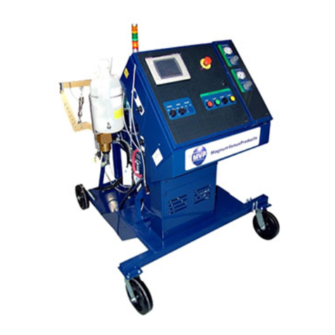
MVP UltraMAX Operating instructions

UltraMAX™
Maintenance & Repair Manual
Magnum Venus Products
UltraMAX™
Chop Fluid Section VLS-4600
Revision05.13.03

UltraMAX™
UltraMAX™
Maintenance&RepairManual
ChopFluidSectionModule
Corporate HQ, Mfg.
Phone:(727)573-2955
Fax: (727) 571-3636
Email:[email protected]
Web:www.magind.com
© 2003 Magnum Venus Products
Manufacturing
Phone: (253) 854-2660 (800) 448-6035
Fax: (253) 854-1666
Email:[email protected]
Web:www.venusmagnum.com

UltraMAX™
CHAPTER 1-GETTINGSTARTED
ToolsRequired
CHAPTER 2-INSTRUCTIONS
Disassembly of Fluid Section
CHAPTER 3-INSTRUCTIONS
Reassemblyof Fluid Section
CHAPTER 4-APPENDIX
FluidSection Part Drawings
TableofContents
UltraMAX™
Maintenance&RepairManual
ChopFluidSectionModule

UltraMAX™
UltraMAX™
Fluid Section
Getting Started
Tools Required
1. ¾”openendwrench
2. ¼”woodendowel-6”
3. ¼”metalrod
4. 12”adjustablewrench
5. Strapwrench
6. Spanner orFordwrench
7. 9/16”Open End Wrench
8. Pliers
1
Chapter
1

UltraMAX™
UltraMAX™
DisassemblyofFluidSection
2
Chapter
2
To remove the Fluid Section from the
UltraMAX™Unit:
1. Remove the APP-9102 (E-Ring), lift up the APP-9109 (Sleeve) and
removethe twoAPP-9096(Connectors).
2. Remove theAPS-1016 (Quick Pin) and slide the 7201-8-1-APS-1016
(RailAssembly) out of the VLS-4613 (Piston RodAdapter).
When removing Resin Pump Fluid Section and Resin Surge
Chamber, be sure to bleed pressure from the system before dis-
connecting hoses or tie rods. Release Surge Chamber charge
before removing Surge Chamber. System may be under pressure
and could cause injury.
WARNING
NOTE
The resin pump can be rebuilt in place or easily removed from
pump column and moved to a workbench.

UltraMAX™3
Fluid Section Disassembly Procedures:
1. Remove the two F-HN-08C (Hex Nuts) from the VLS-4623 (Pump
CylinderTieRods).
2. Slide the VLS-4624 (Foot Valve Collar), VLS-4602 (Foot Valve) and
VLS-4608 Cylinder) down off the VLS-4609 (Piston Rod), discard the
twoO-V-137-90(O-Rings). RemovetheVLS-4620(BallStop)andVLS-
4621 (Foot Valve Spring). Remove and discard the VLS-4622 (1 1/4”
Chrome Ball). Clean and inspect ball seat area of VLS-4602 (Foot
Valve).
3. Loosen VLS-4607 (Packing Nut)andslidetheVLS-4609(PistonRod)
outthebottomoftheVLS-4601 (Outlet Body).
4. Unscrewthe VLS-4618 (PistonNut)fromtheVLS-4619(Piston Body).
RemovethetwoVLS-4615 (PistonCups),VLS-4617(PistonCupBack-
up) and VLS-4616 (Piston Cup Spacer) from the VLS-4619 (Piston
Body). Discard the two VLS-4615 (Piston Cups).
5. Unscrewthe VLS-4619(Piston Body)from theVLS-4609 (PistonRod).
Remove theALS-1018 (7/8” Chrome Ball) and the VLS-4614 (Piston
Ball Spring) Discard theALS-1018 (Chrome Ball – 7/8”)
6. Removethe VLS-4607(PackingNut) fromtheVLS-4601 (OutletBody).
Usea1/4”woodendoweltopushtheVLS-4605(PackingSet Assembly)
out the top of the VLS-4601 (Outlet Body). Discard the packing set.
Cleanand inspect the VLS-4603 (Guide Bearing), VLS-4604 (Female
Compression Ring), VLS-4606 (Male Compression Ring), VLS-4610
(Wave Spring),andVLS-4611(SpringSupport Ring).
7. Clean and inspect all parts that will be reused, replace asneeded.

UltraMAX™
UltraMAX™
ReassemblyofFluidSection
1. UseMVP 6706-2-1(RedGrease) tofill inthefemale sideof eachofthe
four Packings in the VLS-4605 (Packing SetAssembly) and the VLS-
4604(Female CompressionRing). Wipe alightcoat ofRed Grease on
theALS-1018 (7/8” Chrome Ball), and the VLS-4622 (1 1/4“ Chrome
Ball). SmearRedGrease ontheinnerradiuson bothVLS-4615(Piston
Cups). Coatthethreads on the VLS-4607 (Packing Nut) with the Red
Grease.
2. Insert the VLS-4611 (Spring Support Ring) into the VLS-4601 (Outlet
Body),followedby the ten VLS-4610 (WaveSprings). PlacetheVLS-
4605 (Packing set Assembly) on top of the VLS-4606 (Male
Compression Ring). Set the VLS-4604 (Female Compression Ring )
on top of the VLS-4605 (Packing Set Assembly). Place the entire
assembly into the VLS-4601 (Outlet Body) with the female side of the
PackingSetfacing down. Set the VLS-4603 (Guide Bearing) into the
VLS-4601 (Outlet Body). Screw the VLS-4607(Packing Nut) into the
VLS-4601(OutletBody) onlytwoto threethreads.
4
Chapter
3
NOTE
Do not tighten the VLS-4607 (Packing Nut) at this time.

UltraMAX™5
3. Slide one VLS-4615 (Piston Cups) onto the VLS-4619 (Piston Body)
with the open side of the Piston Cup facing up. Slide the VLS-4616
(PistonCupSpacer)withgroovedsideupagainstthePistonCup. Install
the second VLS-4615 (Piston Cup) up against the Piston Cup Spacer
withthe open side up. Slide the 3101-14-1 (Piston Cup Back-up)with
groovesfacingup againstthe PistonCup. Coat thethreadsoftheVLS-
4618(PistonNut),andscrewit ontotheVLS-4619(PistonBody). Place
ALS-1018 (7/8” Chrome Ball) into the VLS-4619 (Piston Body). Set
the VLS-4614 (Piston Ball Spring) into the Piston Body with the small
endof the spring against theALS-1018 (7/8” Chrome Ball).
4. Coat the threads of the VLS-4619 (Piston Body),and screw it onto the
VLS-4609 (Piston Rod). Tighten the VLS-4618 (Piston Nut) and the
VLS-4619(Piston Body) wrench tight.
5. SlidetheVLS-4609(PistonRod)upthroughtheVLS-4601(OutletBody)
andtightentheVLS-4607 (PackingNut) enoughtohold thePiston Rod
inplace.
6. Install VLS-4622 (11/4” Chrome Ball), thenthe VLS-4621(Foot Valve
Ball Spring) into the VLS-4602 (Foot Valve). Compress the VS-4620
(BallStop)andinsert itinto theVLS-4602(FootValve)groove. Position
one end of the VLS-4608 (Cylinder) into the VLS-4602 (Foot Valve).
SlideO-V-137-90(O-Rings)on cylinderand lubricatewith RedGrease.
7. Uselithium grease ontheVLS-4623 (Pump CylinderTie Rod)threads
andscrew into VLS-4601 (OutletBody)if they were removed.
8. Slide the VLS-4608 (Cylinder) with VLS-4602 (Foot Valve) over the
PistonRodAssembly andstarttheF-HN-08C (HexNuts)onto theVLS-
4623(Pump CylinderTieRods). Tightenuniformly untilwrenchtight.
9. Use a 1/4” metal rod, or Phillips screwdriver to tighten the VLS-4607
(PackingNut).
NOTE
Do not drop, dent, or scratch the ALS-1018 (7/8” Chrome Ball)
or VLS-4622 (1 1/4” Chrome Ball).
NOTE
The two VLS-4623 (Pump Cylinder Tie Rods) must be inserted
in opposing holes.

UltraMAX™
To Reinstall onto UltraMAX Unit
1. PositiontheAPP-9109(Sleeve)over the Power CylinderPistonShaft.
Bring the Power Cylinder Piston Shaft down onto the top of the VLS-
4613(Piston RodAdapter). Insert the twoAPP-909 (Connectors) and
lowertheAPP-9109(Sleeve). InstalltheAPP-9102(Ring)in machined
groove.
2. Slide the Rail Assembly around the VLS-4613 (Piston Rod Adapter)
andinsert theAPS-1016(QuickPin).
3. Fillthe packing nutcavity1/2 to2/3full with TSL(ThroatSeal Oil).
6

UltraMAX™7

UltraMAX™
UltraMAX™
Appendix
Parts Drawings
Chapter
4
8

UltraMAX™9

UltraMAX™
10

UltraMAX™11

UltraMAX™
12

UltraMAX™13

UltraMAX™
14

UltraMAX™15

UltraMAX™
16

UltraMAX™17
Table of contents
Other MVP Control Unit manuals
Popular Control Unit manuals by other brands

GEM
GEM 225 Installation, operating and maintenance instructions

Danfoss
Danfoss ICM 20 Installation, programming, and troubleshooting manual

Panasonic
Panasonic SF-C14EX-01 instruction manual

Siemens
Siemens 3SB5 Operating instructions manual

Honeywell Home
Honeywell Home HR91 FAQ & Setup Guide

BENDIX
BENDIX TP-3 TRACTOR PROTECTION VALVE manual