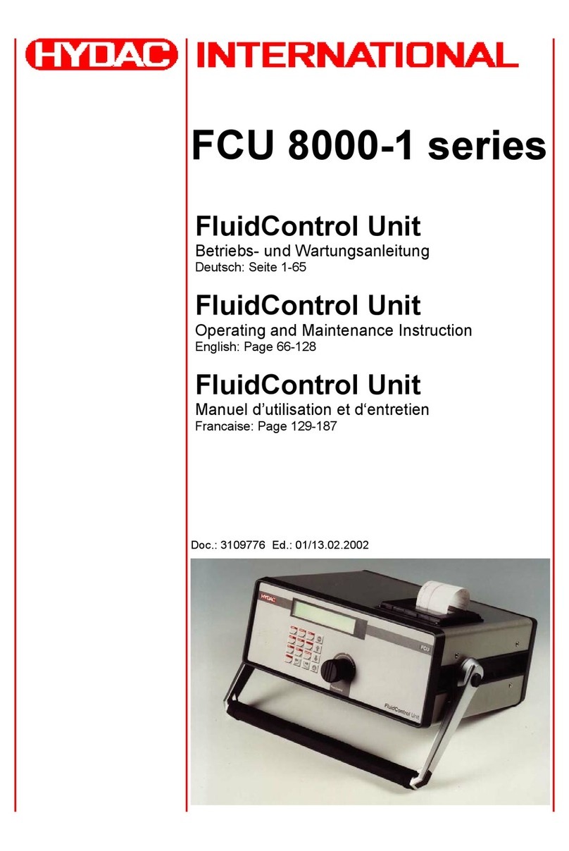
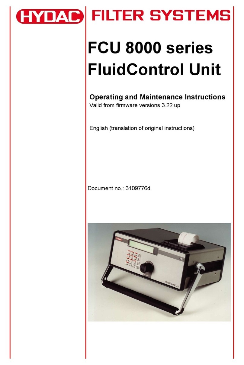
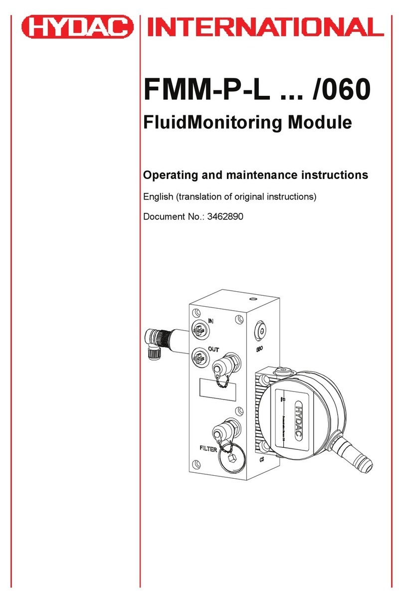
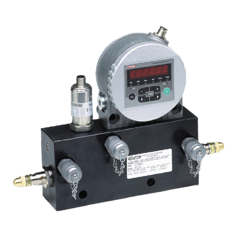
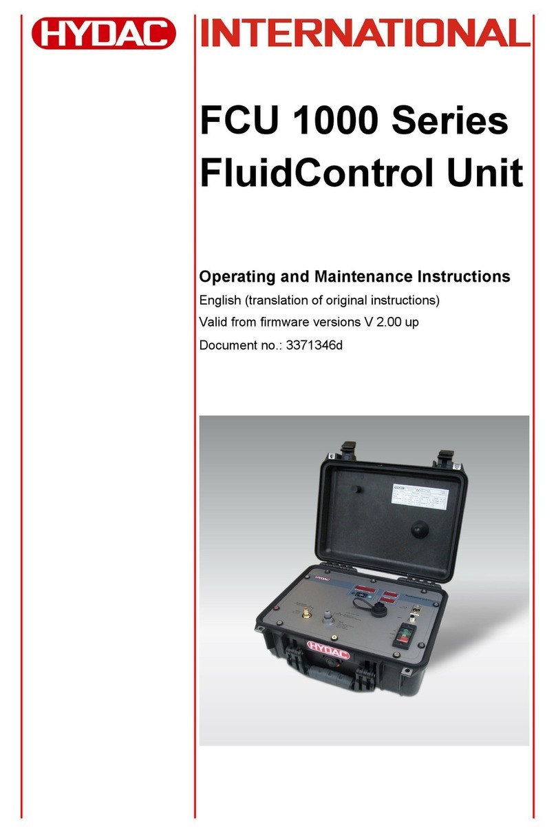
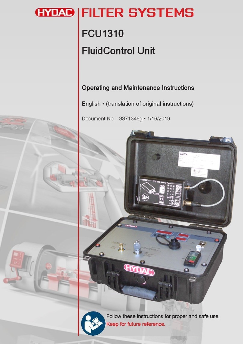
Hydac FCU 5000-T001 User manual

FCU 5000 /-T001
FluidControl Unit
Installation and Maintenance Instructions
English (translation of original instructions)
Documentation no.: 4609526
Keep for future reference.

Content
FCU 5000/-T001
en(us)
Page 2 / 60
MoWa FCU5000 T001 4609526 en-us 2021-10-11.docx
2021-10-11
Content
Content ..........................................................................................................2
General ..........................................................................................................4
Imprint.............................................................................................4
Documentation Representative ......................................................4
Purpose of this manual...................................................................4
Target group of the manual ............................................................5
Target group - Required qualifications / knowledge........................6
Illustrations in the manual...............................................................7
Illustration of the layout ...............................................................7
Representation of procedural instructions...................................8
Representation of warning / general safety information ..............8
Signal words and their meaning in the general safety
information ..................................................................................9
Representation / explanation of pictograms..................................10
Supplementary symbols ...............................................................11
Exclusion of liability / warranty......................................................12
Notes on copyright........................................................................12
Validity of this manual...................................................................12
General Safety Information........................................................................12
Product overview........................................................................................13
Scope of delivery..........................................................................14
Dimensions...................................................................................15
Connections and components......................................................15
Hydraulic diagram of the sensor unit............................................17
The complete hydraulic circuit of the FCU 5000 is included in the
scope of delivery of the device. ....................................................17
Proper/Designated Use ................................................................18
Hazard warnings...........................................................................19
Improper use or use deviating from intended use.........................20
Technical data..............................................................................21
Name plate...................................................................................21
Model Code...............................................................................23
The model code is created according to the following model
code. .........................................................................................23
Transportation and storage .......................................................................24
Assembly, installation and commissioning .............................................25
Design and placement..................................................................25
Hydraulic installation / assembly...................................................25
Electrical installation / assembly...................................................26

Content
FCU 5000/-T001
en(us)
Page 3 / 60
MoWa FCU5000 T001 4609526 en-us 2021-10-11.docx
2021-10-11
Commissioning.............................................................................28
Integration of Modbus TCP and Profinet...................................28
Operation.....................................................................................................28
Switching on / off..........................................................................28
User levels of the FCU 5000.........................................................29
Layout and arrangement of the display (English language
setting)..........................................................................................30
Left navigation bar - Sidebar.....................................................32
System limits..........................................................................32
Measured values....................................................................33
Data memory..........................................................................36
Events....................................................................................36
Settings.....................................................................................36
System settings......................................................................37
Timer settings.........................................................................38
Additional metering settings...................................................39
Input of External Values............................................................39
Measurement and Autostart......................................................40
Downloading the measured values ...........................................41
Maintenance................................................................................................42
Maintenance intervals...................................................................43
Checking / Replacing the hydraulic hose assemblies...................43
Replacing / Cleaning the sensors.................................................44
Checking the pre-filter...................................................................45
Customer Service / Service..........................................................46
Troubleshooting / Error elimination..........................................................46
Decommissioning / Disposal.....................................................................50
Appendix .....................................................................................................51
Parts/Materials in contact with fluid ..............................................51
Spare parts and accessories........................................................51
Spare parts list ..........................................................................51
Accessories...............................................................................52
Accessories - Analog input.....................................................53
Accessories - Digital I/O.........................................................54
Accessories - Metering pump.................................................54
Glossary ......................................................................................................56
Explanation of terms and abbreviations........................................56
Index ............................................................................................................57

General
FCU 5000/-T001
en(us)
Page 4 / 60
MoWa FCU5000 T001 4609526 en-us 2021-10-11.docx
2021-10-11
General
In this chapter, you will find helpful notes on handling these instructions.
Imprint
Publisher and responsible for the content:
HYDAC FILTER SYSTEMS GMBH
Postfach 1251
66273 Sulzbach / Saarland
Germany
Telephone:
+49 6897 509 01
Fax:
+49 6897 509 9046
E-mail:
filtersystems@hydac.com
Homepage:
www.hydac.com
Court of registration:
Saarbrücken, HRB 17216
Executive directors: Mathias Dieter,
Dipl.Kfm. Wolfgang Haering
Documentation Representative
Mr. Günter Harge
c/o HYDAC International GmbH, Industriegebiet, 66280 Sulzbach / Saar
Telephone:
+49 6897 509 1511
Fax:
+49 6897 509 1394
E-mail:
guenter.harge@hydac.com
Purpose of this manual
Please read this manual before you use this product for the first time or if you have
been asked to carry out other work on the product
The use and the handling of the product described below, as well as its operation, are
not self-explanatory and are described in detail in this manual and the associated
technical documentation.
This manual will help you to use the product as intended, properly, effectively, and
safely. Therefore, you are requested to read the following chapters attentively and
carefully. Please refer to it every time you require decisive details.
This manual informs and warns you of risks, against which the risk reduction through

General
FCU 5000/-T001
en(us)
Page 5 / 60
MoWa FCU5000 T001 4609526 en-us 2021-10-11.docx
2021-10-11
the design and protective measures may not be effective or not fully effective.
Target group of the manual
This manual was created for the following target group.
Target group
Tasks
Owner This manual and the associated documents must be kept
accessible at the installation location of the product and
also for later use.
Ask the employees to read and follow the manual and the
documents delivered along with it, in particular, the safety
and warning instructions.
Observe the additional product-related instructions and
requirements.
Specialist
personnel Read, observe and follow this manual and the associated
documents, in particular, the safety and warning
instructions.

General
FCU 5000/-T001
en(us)
Page 6 / 60
MoWa FCU5000 T001 4609526 en-us 2021-10-11.docx
2021-10-11
Target group - Required qualifications / knowledge
Persons who work on the product must be aware of the hazards associated with its
use.
Auxiliary and specialist personnel must have read and understood the operating
instructions, in particular the safety information and instructions, and applicable
regulations before beginning work.
The operating instructions and applicable regulations are to be retained so they are
accessible to operating and specialist personnel.
These operating instructions are intended for:
Auxiliary personnel:such persons have been instructed about the product and
informed about potential hazards that can result from improper use.
Specialist personnel: such persons with corresponding specialist training and several
years' work experience. They are able to assess and perform the work assigned to
them, they are also able to recognize potential dangers.
Activity Person Knowledge
Transport / storage Forwarding
agent
Auxiliary
personnel
•No special knowledge
required
Hydraulic / electrical
installation,
First commissioning
Maintenance,
Troubleshooting,
Repair,
Decommissioning,
Disassembly
Specialist
personnel •Safe handling/use of
tools
•Fitting and connection
of hydraulic pipelines
and connections
•Fitting and connection
of electrical lines,
electrical machinery,
sockets, etc.
•Product-specific
knowledge
Operation
Operations control Specialist
personnel •Product-specific
knowledge
•Knowledge about how
to handle the operating
media.
Disposal Specialist
personnel •Knowledge about reuse

General
FCU 5000/-T001
en(us)
Page 7 / 60
MoWa FCU5000 T001 4609526 en-us 2021-10-11.docx
2021-10-11
Illustrations in the manual
You will find illustrations in this manual. You can find details regarding these in the
following chapters.
Illustration of the layout
de
HYDACFiltertechnikGmbH
BeWa123456ade
Seite x
Produkt/Kapitel
200x-xx-xx
The documentation number with its index enables you to order another copy of the
operating instructions. The index is incremented every time the manual is revised or
changed.
Note that the method described for locating specific information
does not release you from your responsibility of carefully reading
these instru
ctions prior to starting the unit up for the first time and
at regular intervals in the future.
The manual contains a table of contents, an index and a glossary.
Chapter description
Page number
Edition date
Documentation language
Documentation no.
with index /
file name

General
FCU 5000/-T001
en(us)
Page 8 / 60
MoWa FCU5000 T001 4609526 en-us 2021-10-11.docx
2021-10-11
Representation of procedural instructions
The following two illustrations differ with regard to procedural instructions:
Procedural instructions with a fixed sequence
Procedural instructions, whose sequence must be complied with without fail, are listed
with sequential numbering (1., 2., 3., etc.).
An example of procedural instructions with a fixed sequence:
1. Remove the transport securing device.
2. First fill the product.
3. Switch the product on.
Procedural instructions with a random sequence
Procedural instructions that have a random sequence are listed as bullet points (-).
Example of a procedural instruction with a random sequence:
- Clean the display
- Flush the product
Representation of warning / general safety information
All the warning / general safety information in this manual are highlighted with
pictograms and signal words. The pictogram and the signal word indicate the severity
of the danger.
Warning / general safety information is listed before an activity and is laid out as
follows.
HAZARD SYMBOL
SIGNAL WORD
Type and source of danger
Consequence of the danger
►Measures to avert the danger

General
FCU 5000/-T001
en(us)
Page 9 / 60
MoWa FCU5000 T001 4609526 en-us 2021-10-11.docx
2021-10-11
Signal words and their meaning in the general safety information
In these instructions you will find the following signal words:
DANGER
DANGER –
The signal word indicates a hazardous situation with a high level
of risk, which, if not avoided, will result in death or serious injury.
WARNING
WARNING –
The signal word indicates a hazardous situation with a medium
level of risk, which, if not avoided, can result in death or serious injury.
CAUTION
CAUTION –
The signal word indicates a hazardous situation with a low level
of risk, which, if not avoided, can result in minor or moderate injury.
NOTICE
NOTICE – The signal word indicates a hazardous situation with a high level
of risk, which, if not avoided, will result in damage to property.
ENVIRONMENTALLY TIP
ENVIRONMENTALLY TIP –
The signal word indicates a hazardous situation
without a high level of risk, which, if not avoided, will result in environmental
contamination.

General
FCU 5000/-T001
en(us)
Page 10 / 60
MoWa FCU5000 T001 4609526 en-us 2021-10-11.docx
2021-10-11
Representation / explanation of pictograms
The following safety symbols / pictograms can be found in this manual. They indicate
specific dangers to persons, property or to the environment. Observe these safety
symbols / pictograms and act with particular caution in such cases. Always keep all
symbols / pictograms complete and legible.
Warning signs used
These signs are listed for all general safety information and instructions in these
operating instructions which indicate particular dangers to persons, property or the
environment.
Danger point warning
Danger due to operating pressure
Warning about dangerous electrical voltage
GHS signs used
These symbols can be found with all the safety and warning instructions in this manual
which indicate particular dangers to persons, property or the environment.
Danger from environmentally hazardous substances
Danger due to substances which can be hazardous to
your health
Signs used for giving orders
These symbols are listed for all general safety information and instructions in these

General
FCU 5000/-T001
en(us)
Page 11 / 60
MoWa FCU5000 T001 4609526 en-us 2021-10-11.docx
2021-10-11
operating instructions that refer to particular dangers to persons, property or the
environment.
Disconnect before maintenance or repair
Signs used for the required specialist personnel
These symbols show the required training / knowledge for installation work and / or
maintenance work.
Specialist personnel - Electrical
These persons have specific specialist training
and several years of work experience. They are
able to assess and perform the work assigned to
them, they are also able to recognize potential
dangers.
Specialist personnel - Mechanical
These persons have specific specialist training
and several years of work experience. They are
able to assess and perform the work assigned to
them, they are also able to recognize potential
dangers.
Supplementary symbols
You will find the following symbols in the manual as additional details:
Tip for handling the product
Required tools

General Safety Information
FCU 5000/-T001
en(us)
Page 12 / 60
MoWa FCU5000 T001 4609526 en-us 2021-10-11.docx
2021-10-11
Exclusion of liability / warranty
For the warranty provided by us, please refer to our terms of delivery. They are made
available to you at the conclusion of the contract at the latest. You can also find them
under www.hydac.com → General Terms and Conditions.
This manual was prepared to the best of our knowledge. Nevertheless and despite the
greatest care, it is possible that it may contain errors. Therefore please understand
that, in the absence of any provisions to the contrary hereinafter, our warranty and
liability – for any legal reasons whatsoever – are excluded in respect of the information
in these instructions. In particular, we shall not be liable for lost profit or other financial
loss.
This exclusion of liability does not apply in cases of intent and gross negligence.
Moreover, it does not apply to defects which have been deceitfullyconcealed or whose
absence has been guaranteed, nor in cases of culpable harm to life, physical injury
and damage to health. If we negligently breach any material contractual obligation, our
liability shall be limited to foreseeable damage. Claims due to the product liability shall
remain unaffected.
Notes on copyright
All copyrights for this manual lie with the manufacturer. No part of this manual may be
reproduced in any form or processed or duplicated using electronic systems without
the written consent of the manufacturer. Any infringements to the above shall be liable
to damage compensation.
Validity of this manual
The diagrams and visualizations in this manual are meant for general illustration
purposes. Therefore, representations and functional options can deviate from those of
the delivered product.
We reserve the right to make changes to the contents of this manual without prior
notice.
General Safety Information
The product has been built according to the provisions, directives and standards valid
at the time of delivery and satisfies the current safety requirements. Any residual
hazards are indicated by the general safety information and are described in this
manual.
Observe all the safety and warning instructions attached to the product and always
keep them up to date and easily legible.

Product overview
FCU 5000/-T001
en(us)
Page 13 / 60
MoWa FCU5000 T001 4609526 en-us 2021-10-11.docx
2021-10-11
Product overview
The FCU 5000 is a stationary online measurement device to monitor the essential fluid
parameters in water-based cooling lubricant systems. This includes the pH value,
conductivity, refractive index, and temperature. Automated additional metering of the
cooling lubricant concentrate (optional) ensures that the required concentration can be
maintained at an almost constant level in the system.
The FCU 5000 is connected in the bypass for the central circulation of the system. It
monitors the fluid parameters continuously and stores the derived values. The limit
values of the measured values are monitored. If the measured values depart from the
set limits, a signal is sent to the display via the electrical interfaces.
A flushing and self-monitoring function ensures that there are no dirt deposits in the
device and guarantees the validity of the measured values. Any deviations in the
measurement are corrected by checking the zero point. Externally derived measured
values can be imported to the USB memory stick of the FCU 5000.
The system is controlled by means of the touch panel on the device (optional), the
integrated web server or the desktop software.
The integration of the FCU 5000 in a cooling lubricant system can appear as follows:

Product overview
FCU 5000/-T001
en(us)
Page 14 / 60
MoWa FCU5000 T001 4609526 en-us 2021-10-11.docx
2021-10-11
Item
Designation
1
Consumer
2
Cooling lubricant concentrate
3
pH stabilizer
4
Bypass line
5
Metering pump 1
6
Metering pump 2
7
Needle valve
8
Protective filter
9
Belt filter
10
Central reversing pump
11
Dirt tank
12
Clean tank
13
Central system
1 4
Public water supply (with backflow preventer)
Scope of delivery
The FCU 5000 is packed and delivered in a pre-assembled condition. Before
commissioning, check the delivery for completeness and transportation damage.
The following items are included in the scope of delivery:
Qty
Designation
1
FCU 5000
1
pH sensor in a special package*
1
Switch cabinet key
1
USB memory stick
1
Power supply adapter (optional)
1
Power supply plug**
1
Technical documentation consisting of:
- Installation and Maintenance Instructions (this document)
- Electrical circuit diagram
- Hydraulic Diagram
- Instructions for Modbus TCP
- Instructions for Profinet
* Please save the packaging for storing and sending in for calibration
** Please keep when not in use

Product overview
FCU 5000/-T001
en(us)
Page 15 / 60
MoWa FCU5000 T001 4609526 en-us 2021-10-11.docx
2021-10-11
Dimensions
All dimensions in mm.
Connections and components

Product overview
FCU 5000/-T001
en(us)
Page 16 / 60
MoWa FCU5000 T001 4609526 en-us 2021-10-11.docx
2021-10-11
Item
Designation
Components
A Operating unit and touch panel (option) with electrical
connections
B
Sensor unit with hydraulic connections
Electrical connectors
1
Main switch
2 Ethernet interface to communicate via the web server and the
desktop application
3
Profinet / Modbus TCP interface for data transmission (option)
4
4 – 20 mA analog input for an external tank level sensor
5
4 – 20 mA analog input for an external pressure sensor
6
24 VDC 5A supply voltage
7
Switching output of metering pump 1
8
Switching output of metering pump 2
9
USB port for data backup
Hydraulic connections
10
Port 1 for the cooling lubricant
11
Port 2 for the device flushing medium
12
Port 3 for the refractometer flushing medium
13
Port 4 for the return line to the tank

Product overview
FCU 5000/-T001
en(us)
Page 17 / 60
MoWa FCU5000 T001 4609526 en-us 2021-10-11.docx
2021-10-11
Hydraulic diagram of the sensor unit
The complete hydraulic circuit of the FCU 5000 is included in the
scope of delivery of the device.
Item
Designation
IN
Port 1 for the cooling lubricant
RINSE I
Port 2 for the device flushing medium
RINSE II
Port 3 for the refractometer flushing medium
OUT
Port 4 for the return line to the tank
QM1, QM2, QM3
Two-way valves
BF1
Flow transmitter
BT1
Temperature sensor
BP1
Pressure sensor
BQ1
pH sensor
BQ2
Conductivity sensor
BQ3
Refractometer

Product overview
FCU 5000/-T001
en(us)
Page 18 / 60
MoWa FCU5000 T001 4609526 en-us 2021-10-11.docx
2021-10-11
Proper/Designated Use
Use the unit only for the application described below.
The FCU 5000 is a stationary online measurement device to determine the fluid state
in cooling lubricant systems.
Proper/designated use of the product extends to the following:
- Maintaining adherence to all the instructions contained herein.
- Ensuring the execution of all inspection and maintenance work.
NOTICE
Impermissible operating media
The FCU 5000 can be damaged.
►Only use operating media which is compatible with the installed
materials and sealing materials. (See Appendix)
NOTICE
Missing external valve for the flushing medium
Danger of the tank overfilling during the flushing operation of the
FCU 5000.
►The external valve of the flushing medium must be switched by the
owner to monitor the filling level.
Claims for defects or liability – regardless of the legal foundation – do not apply with
incorrect or improper installation, commissioning, usage, handling, storage,
maintenance, repair, use of unsuitable operating medium or other circumstances for
which the manufacturer is not responsible.
The manufacturer assumes no responsibility for determining the interfaces for
installation in a system or the installation, use or functionality of the product in this
system.

Product overview
FCU 5000/-T001
en(us)
Page 19 / 60
MoWa FCU5000 T001 4609526 en-us 2021-10-11.docx
2021-10-11
Hazard warnings
NOTICE
No pre-filtration
The FCU 5000 can be damaged.
►The FCU 5000 may only be operated with adequate pre-filtration.
►
NOTICE
Pressure buildup in the return line
The FCU 5000 can be damaged.
►The FCU 5000 must not be operated if there is pressure of more than
1.5 bar at the outlet of the device.
►
NOTICE
No backflow preventer
Risk of contamination of the public water supply.
►If the FCU 5000 is operated with a connection to the public water
supply, then a backflow preventer must be installed in accordance with
the German Wasserhaushaltsgesetz (WHG) or the Federal Water Act.
For other countries, check the state laws.
►
NOTICE
►No level sensor
►Danger of the tank overfilling during the flushing operation of the
FCU 5000.
►The FCU 5000 may be operated only if a suitable level sensor with an
analog measured value resolution is used or, alternatively, the tank
level is transmitted to the FCU 5000 via Profinet or Modbus TCP.

Product overview
FCU 5000/-T001
en(us)
Page 20 / 60
MoWa FCU5000 T001 4609526 en-us 2021-10-11.docx
2021-10-11
Improper use or use deviating from intended use
Any other use or extended use shall not be considered intended use. HYDAC Filter
Systems GmbH will assume no liability for any damage resulting from such use. This
risk is borne solely by the owner.
Improper use may result in hazards and/or will damage the product. Examples of
improper use include:
•Operation with a non-approved fluid.
•Operation under non-approved operational conditions.
•Operation with defective or unsuitable safety devices.
•Unauthorized modifications to the unit.
•Inadequate monitoring of the device parts that are subject to wear.
•Improperly performed repair work.
This manual suits for next models
1
Table of contents
Other Hydac Control Unit manuals
Popular Control Unit manuals by other brands

RS
RS EDP-CM-1113 Getting started guide

WAREMA
WAREMA WMS Splitter UP Operating and installation instructions

YASKAWA
YASKAWA SLIO CP 042-1IO00 manual

ProSoft Technology
ProSoft Technology MVI69E-GEC user manual

Cutler-Hammer
Cutler-Hammer Digitrip OPTIM 550 installation instructions

Honeywell
Honeywell MK VI pilot's guide