MW TOOLS CUT45HF User manual

M1.2.CUT45HF.NLFREN 09102018
HANDLEIDING - MODE D’EMPLOI - MANUAL
CUT45HF (829300220)
Plasmasnijder
Découpeur plasma
Plasma cutter
P.02 Gelieve te lezen en voor later gebruik bewaren
P.16 Veuillez lire et conserver pour consultation ultérieure
P.30 Please read and keep for future reference
FR
EN
NL
copyrighted document - all rights reserved by FBC

M1.2.CUT45HF.NLFREN 09102018
2
NL
Inhoud
1 Veiligheid ���������������������������������������������������������������������������������������������������������������������������������� 3
1.1 Veiligheidsvoorschriften bij de installatie ................................................................................................... 3
1.2 Veiligheidsvoorschriften bij het gebruik ..................................................................................................... 3
1.3 Veiligheidsvoorschriften bij het verwijderen................................................................................................ 4
2 Algemene omschrijving�������������������������������������������������������������������������������������������������������������� 4
2.1 Technische parameters............................................................................................................................ 4
2.2 Samenstelling van het plasmasnijsysteem .................................................................................................. 5
2.3 Functies en kenmerken van de machine..................................................................................................... 5
2.4 Kenmerken van het systeem ..................................................................................................................... 6
3 Installatie en aansluiting������������������������������������������������������������������������������������������������������������ 7
3.1 Aansluitingsvoorwaarden........................................................................................................................ 7
3.2 Veiligheidsvoorschriften........................................................................................................................... 8
4 Gebruik ������������������������������������������������������������������������������������������������������������������������������������� 9
4.1 Functies van de voor- en achterpanelen..................................................................................................... 9
4.2 Digitaal paneel ................................................................................................................................... 10
4.3 Werkmethode ..................................................................................................................................... 11
4.4 Aanbevelingen voor een correct snijden ................................................................................................. 11
4.5 Snijparameters tabel ............................................................................................................................ 12
4.6 De elektrode en het mondstuk vervangen................................................................................................ 12
5 Onderhoud ������������������������������������������������������������������������������������������������������������������������������ 13
5.1 Dagelijks onderhoud............................................................................................................................ 13
5.2 Periodieke controle............................................................................................................................... 14
6 Storingen��������������������������������������������������������������������������������������������������������������������������������� 15
7 EG conformiteitsverklaring ������������������������������������������������������������������������������������������������������� 44
copyrighted document - all rights reserved by FBC

3
NL
M1.2.CUT45HF.NLFREN 09102018
1 Veiligheid
1�1 Veiligheidsvoorschriften bij de installatie
Pas op voor elektrische schokken!
• Installeer een grondleiding.
• Raak nooit aan delen onder spanning met blote handen, of met natte handschoenen/
kleren.
• Maak zeker dat u goed geïsoleerd ben van de grond en van het werkstuk.
• Sluit de afdekkap van de machine voor het inschakelen, om elektrische schokken te
voorkomen.
• Maak zeker dat uw werkhouding veilig is.
Pas op voor brandgevaar!
• Installeer de machine op een onbrandbaar materiaal, om een brand te voorkomen.
• Maak zeker dat er geen brandbare producten in de buurt van de werkruimte zijn.
Pas op voor explosiegevaar!
• Installeer de machine niet in een omgeving met explosieve gassen.
AANDACHT!
Componenten vervangen kan gevaarlijk zijn�
• De vervanging van componenten moet door gekwaliceerd personeel uitgevoerd worden.
• Zorg ervoor, dat er geen vreemde voorwerpen zoals elektrische kabels, schroeven, pakkingen,... in de
machine vallen tijdens de vervanging van componenten.
• Na de vervanging van de PCB’s, maak zeker dat de aansluitkabels in de machine correct aangesloten zijn.
Alleen dan mag de machine ingeschakeld worden, zonder gevaar voor schade.
1�2 Veiligheidsvoorschriften bij het gebruik
De rook kan schadelijk voor de gezondheid zijn!
• Houd uw hoofd ver van de rook en de gassen om deze niet in te ademen.
• Ventileer de werkruimte met een afzuigsysteem of een ventilatie.
De boogstraling is gevaarlijk voor de ogen en de huid!
• Draag een masker, beschermende kleren en lashandschoenen.
• Gebruik maskers of een scherm om eventueel toeschouwers te beschermen.
Het elektromagnetische veld kan een pacemaker beïnvloeden!
• Mensen met een pacemaker moeten hun arts raadplegen voordat ze met de machine
werken.
• Blijf weg van de stroombron, om de effecten van het magnetische veld te verminderen.
Een ongeschikt gebruik van de machine kan een brand of een ontplofng
veroorzaken!
• Vonken kunnen brand veroorzaken. Zorg ervoor dat er geen brandbaar materiaal in de
omgeving liggen.
• Zorg ervoor dat er een brandblusser is in de nabijheid, en dat iemand deze kan
gebruiken.
• Snij nooit een gesloten container.
• Gebruik dit toestel niet om leidingen te ontdooien.
SAFETY
Precautions for installation
Beware of electric shock!
Install grounding device according to application standard.
Do not touch live parts with naked skin, wet gloves or wet clothes.
Be sure you are insulated from ground and workpiece.
Cover the cover plate of the machine before power on to avoid an
electric shock.
Confirm the safety of your working position.
Beware of fire hazard!
Please install the machine on non-combustible materials to avoid
a fire.
Make ensure there are no inflammables near the cutting position
to avoid a fire.
Beware of explosion !
Do not install the machine in an environment with explosive gas
to avoid an explosion.
Replacing the components can be dangerous.
Only professionals can replace the components of the machine.
Make sure the connecting wires inside the machine are correctly connected after replacing
the PCBs, and then the machine can be run. Otherwise, there is a risk of damage to
property.
Make sure there are no foreign bodies such as wire leads, screws, gaskets and metal bars
falling into the machine inside when replacing the components.
6/ 25
Z210 SC-A0
Arc radiation-may hurt your eyes and burn your skin!
Use proper welding mask and wear protective clothing to protect
your eyes and body.
Use proper mask or curtain to protect onlooker from being
injured.
Improper use and operation may result in fire or explosion
Welding spark may result in fire, so please make ensure there
are no inflammables near the welding position, and pay
attention to fire safety.
Ensure there is fire extinguisher nearby, and make sure
someone has been trained to operate the fire extinguisher.
Do not weld closed container.
Do not use this machine for pipe thawing.
Hot workpiece can cause severe scald.
Do not touch hot workpiece with bare hands.
Cool the welding torch for a while after continuously working.
Excessive noise does great harm to people’s hearing.
Wear ear covers or other hearing protectors when welding.
Give warning to onlooker that noise may be potentially
hazardous to hearing.
Magnetic field can make cardiac pacemaker a bit wonky.
People with cardiac pacemaker should stay away from the
welding spot without first talking to a doctor.
Moving parts may injure your body.
Please keep away from moving parts (like fan).
Each door, panel, cover, baffle plate, and protective device the
like should be closed and located correctly.
copyrighted document - all rights reserved by FBC

M1.2.CUT45HF.NLFREN 09102018
4
NL
Warme stukken kunnen brandwonden veroorzaken!
• Raak nooit aan warme stukken met blote handen.
• Laat de snijtoorts afkoelen na gebruik.
Een te hoog geluidsniveau kan uw gehoor beschadigen!
• Draag een gehoorbescherming tijdens de laswerken.
• Waarschuw de toeschouwers dat het geluid gevaarlijk kan zijn voor hun gehoor.
Bewegende delen kunnen letsels veroorzaken!
• Blijf niet in de nabijheid van bewegende delen zoals waaiers.
• Tijdens het werk moeten de deuren, panelen, deksels en andere afschermingen
gesloten zijn.
In geval van problemen, neem contact op met een vakman!
• Lees het betreffende hoofdstuk van die handleiding in geval van moeilijkheden bij
de installatie of het gebruik van die machine.
• Indien u een probleem met behulp van de handleiding niet kan oplossen,
contacteer de technische dienst van uw verdeler.
1�3 Veiligheidsvoorschriften bij het verwijderen
Pas op voor de volgende punten bij het verwijderen van de gebruikte machine:
• De elektrolytische condensatoren in de belangrijkste circuit of op de PCB’s verbranden kan een explosie veroorzaken.
• Kunststof onderdelen verbranden, zoals het voorpaneel, kan schakelijke gassen produceren.
• Verwijder de gebruikte machine als industrieel afval.
2 Algemene omschrijving
2�1 Technische parameters
Kenmerken CUT45HF
Stroomvoeding Een fase AC 230 V 50 Hz
Ingangsvermogen 6,45 kVA
Krachtfactor 0,70
Nominale capaciteit 40 V / 96 A
Inschakelduur 35 %
Tension à vide 250 V
Regelbereik 20 - 45 A
Boogontsteking modus HF
Post-ow tijd 5 sec
Werkdruk 4,5 bar
Isolatiegraad F
Afkoelmodus Luchtafkoeling
Beschermingsklasse behuizing IP21S
Rendement 85 %
Afmetingen (l x b x h) 439 x 165 x 327,5 mm
Gewicht 9,2 kg
6/ 25
Z210 SC-A0
Arc radiation-may hurt your eyes and burn your skin!
Use proper welding mask and wear protective clothing to protect
your eyes and body.
Use proper mask or curtain to protect onlooker from being
injured.
Improper use and operation may result in fire or explosion
Welding spark may result in fire, so please make ensure there
are no inflammables near the welding position, and pay
attention to fire safety.
Ensure there is fire extinguisher nearby, and make sure
someone has been trained to operate the fire extinguisher.
Do not weld closed container.
Do not use this machine for pipe thawing.
Hot workpiece can cause severe scald.
Do not touch hot workpiece with bare hands.
Cool the welding torch for a while after continuously working.
Excessive noise does great harm to people’s hearing.
Wear ear covers or other hearing protectors when welding.
Give warning to onlooker that noise may be potentially
hazardous to hearing.
Magnetic field can make cardiac pacemaker a bit wonky.
People with cardiac pacemaker should stay away from the
welding spot without first talking to a doctor.
Moving parts may injure your body.
Please keep away from moving parts (like fan).
Each door, panel, cover, baffle plate, and protective device the
like should be closed and located correctly.
7 / 25
Z210 SC-A0
Seek professional support when trouble strikes.
When trouble strikes in installation and operation, please
inspect according to related contents in this manual.
If you still cannot understand fully, or you still cannot solve the
problem, please contact the dealer or the service center of
JASIC to obtain professional support.
2. SYMBOL EXPLANATION
Matters to be noticed in operation
Objects to be specially described and pointed out
More details in CD
It is prohibited to dispose the electrical waste together with other common
wastes. Please protect the environment.
3. PRODUCT OVERVIEW
Unique electric structure and air channel design in this
series of machines can speed up the heat rejection of the
power device as well as improving the duty cycles of the
machines. The unique heat rejection efficiency of the air
channel can effectively prevent the power devices and
control circuits from being damaged by the dust absorbed
by the fan, and the reliability of the machine is greatly
improved thereby.
The whole machine is in form of coherent streamline, the
front and rear panels are naturally integrated via
large-radian transition manner. The front panel and the
rear panel of the machine and the handle are coated with
rubber oil①, so the machine has soft texture, good hand
feeling, and seems warm and pleasant.
①: Not every piece of machine has the same design.
Differences may exist upon customers’ requirements.
Fig. 1
6/ 25
Z210 SC-A0
Arc radiation-may hurt your eyes and burn your skin!
Use proper welding mask and wear protective clothing to protect
your eyes and body.
Use proper mask or curtain to protect onlooker from being
injured.
Improper use and operation may result in fire or explosion
Welding spark may result in fire, so please make ensure there
are no inflammables near the welding position, and pay
attention to fire safety.
Ensure there is fire extinguisher nearby, and make sure
someone has been trained to operate the fire extinguisher.
Do not weld closed container.
Do not use this machine for pipe thawing.
Hot workpiece can cause severe scald.
Do not touch hot workpiece with bare hands.
Cool the welding torch for a while after continuously working.
Excessive noise does great harm to people’s hearing.
Wear ear covers or other hearing protectors when welding.
Give warning to onlooker that noise may be potentially
hazardous to hearing.
Magnetic field can make cardiac pacemaker a bit wonky.
People with cardiac pacemaker should stay away from the
welding spot without first talking to a doctor.
Moving parts may injure your body.
Please keep away from moving parts (like fan).
Each door, panel, cover, baffle plate, and protective device the
like should be closed and located correctly.
copyrighted document - all rights reserved by FBC

5
NL
M1.2.CUT45HF.NLFREN 09102018
2�2 Samenstelling van het plasmasnijsysteem
第一章 产品概述
3
1.4 Composition and configuration of the cutting machine system
1)Composition
Figure 1-3: Composition of the cutting machine system
2 Configuration)
Table 1-3: Configuration of CUT40(L202)
Table 1-4: Configuration of CUT40C(L203)
Cutting machine
1. GENERAL DESCRIPTION
CUT40(L202)
300A-6mm²-KDP16D(3m)
LT50
Name Specification
Quantity pcs ( )
Remark
Material code
Cutting torch
Earth clamp
Operator’s manual
L2030A SC/A0
Standard configuration
10048700
10003276
10048735
10048725
1
1
1
1
Cutting machine CUT40 (L203)C
300A-6mm²-KDP16D(3m)
PT40-S
Name Specification
Quantity pcs ( )
Remark
Material code
Cutting torch
Earth clamp
Operator’s manual
L2030A SC/A0
Standard configuration
10047859
10003276
10048736
10048725
1
1
1
1
Samenstelling:
• Snijmachine
• Snijtoorts
• Aardingsklem
2�3 Functies en kenmerken van de machine
De CUT45HF is een draagbare plasmasnijmachine, die voor diverse toepassingen geschikt is. Ze kan zowel voor
manueel snijden als voor werken met een robot gebruikt worden. De machine kan geleidende metalen snijden, zoals
laag koolstofstaal, roestvrijstaal en aluminium. De snijdikte kan 25,4 mm bereiken, en de perforeerdikte 12 mm.
Geavanceerde digitale controle modus
De CUT45HF gebruikt de MUC intelligente digitale controle technologie, en alle belangrijkste onderdelen worden door
middel van de software uitgevoerd. Zijn werking en zijn rendement zijn aanzienlijk verbetert in vergelijking met deze van
een traditionele plasma snijmachine.
Geavanceerde inverter technologie
Dankzij de geavanceerde inverter technologie, zijn de omvang en het gewicht van de plasma snijmachine aanzienlijk
verminderd, en de conversie efciëntie wordt sterk verbeterd. De schakelfrequentie ligt buiten het audiospectrum, wat de
geluidsoverlast vrijwel elimineert.
Goede consistentie en stabiele prestaties
In het algemeen, worden de prestatiekenmerken van analoge snijmachine door de parameters van de verschillende
componenten bepaald. De snijcapaciteit van machines verschillen van elkaar als gevolg van incompatibele parameters
van de componenten. Zelfs voor snijmachine van het zelfde merk, zijn de componenten vaak verschillend van elkaar.
Bovendien kan het snijvermogen van de snijmachine op zekere hoogte wijzigen, omdat de parameters van de
bestanddelen kunnen variëren, afhankelijk van de omgeving (temperatuur, vochtigheid, ...).
Een van de kenmerken van de digitale controle is dat deze niet gevoelig is voor de veranderingen van parameters. De
prestatie van de machine zal dus niet door de wijziging van parameters van bepaalde onderdelen beïnvloed worden.
Daarom zijn de consistentie en de stabiliteit van een snijsysteem met digitale controle beter dan traditionele snijmachines.
copyrighted document - all rights reserved by FBC

M1.2.CUT45HF.NLFREN 09102018
6
NL
Krachtige snijprestaties
Deze machine is economisch en praktisch, omdat ze metalen kan snijden, met behulp van perslucht als plasma gasbron.
De snijsnelheid is met 1,8 maal toegenomen in vergelijking met autogeen snijden. De machine kan dikke platen zoals
roestvrij staal, koper, gietijzer en aluminium snel en gemakkelijk snijden. De boog is gemakkelijk te ontsteken, dankzij de
HF boogontstekingsmodus, en de post-ow functie is beschikbaar. Met eenvoudige bediening en hoge snijsnelheid kan
een glad snijvlak verkregen worden, en polijsten is overbodig.
2�4 Kenmerken van het systeem
5
1.6 System characteristics
Figure 1-4: Duty cycle
Figure 1-5: Output characteristic curves
1) Duty cycle
2) Output characteristics
External characteristic of maximum output
External characteristic of minimum output
Relationship with ratedload
1. GENERAL DESCRIPTION
Rated duty cycle refers to the percentage of the normal work time of the machine under rated
maximum current holding in the period when taking 10 minutes as a period. The rated duty
cycle of this machine is 35%. Using the cutting machine continuously overrunning the rated load
may lead to overheating of the machine, and frequently using the machine overrunning the rated
load may accelerate the aging of the machine or even burn the machine.
Q(%)
100
(A)I
80
60
40
20
5040
30
20
10
0
U2(V)
U0
2(A)I
0
1) Inschakelduur
De inschakelduur verwijst naar het percentage normale werktijd van de machine
onder de nominale maximale stroom tijdens een periode van 10 minuten. De
nominale inschakelduur van deze machine is 35 %. Een continu gebruik van de
machine met overschrijding van de nominale belasting kan tot een oververhitting
leiden, en een frequent gebruik met meer dan de nominale belasting kan een
overmatige slijtage veroorzaken, of zelfs de machine verbranden.
2) Uitgangskenmerken
Externe kenmerk van maximale uitgang
- - - - - - - - Externe kenmerk van minimale uitgang
_ _ _ _ _ Verhouding met nominale last
Inschakelduur
Uitgangskenmerken curven
copyrighted document - all rights reserved by FBC

7
NL
M1.2.CUT45HF.NLFREN 09102018
3 Installatie en aansluiting
3�1 Aansluitingsvoorwaarden
1) Aansluiting van de ingangskabel
Voor uw veiligheid, en om elektrische schokken te voorkomen, verbind de machine op betrouwbare wijze aan de aarde,
door de aardingsdraad (geel-groen) van de machine aan de aardingsaansluiting van de schakeldoos aan te sluiten.
Een primaire voedingskabel is beschikbaar voor deze snijmachine. Sluit de voedingskabel aan het nominale
ingangsvermogen aan. De primaire kabel moet aan de correcte stopcontact goed aangesloten worden, om oxidatie te
voorkomen.
Controleer met een multimeter, of de spanning in aanvaardbaar bereik varieert.
De doorsnede van de leidingen in de schakeldoos moet aan de vereisten van de maximale ingangsvermogen van de
machine voldoen.
De machine moet in de nabijheid van een geschikt stopcontact geïnstalleerd worden. Voor een CSA of CE standaard
stroomvoeding, moet een eenfasig 200 ~ 240 V stopcontact gebruikt worden. Een 3 m voedingskabel is beschikbaar
voor de CUT45HF. Er moet een ruimte van minstens 0,25 m³ rondom de stroomvoorziening zijn, om een voldoende
ventilatie te garanderen.
Schakelaar
Installeer een schakelaar op elke stroomvoeding, zodat de stroomvoeding bij
noodgeval onmiddellijk losgekoppeld kan worden. De ontkoppelingswaarde van
de schakelaar moet gelijk aan of groter zijn dan het continue vermogen van de
zekering. Bovendien, moet de schakelaar de volgende kenmerk hebben:
• De stroomvoeding is uitgeschakeld wanneer de schakelaar op “OFF” is.
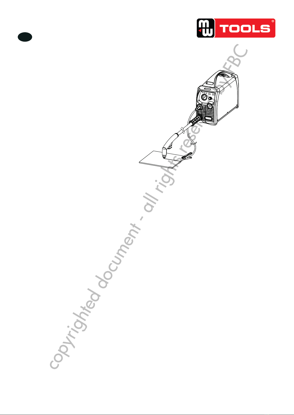
2) Aansluiting van de uitgangskabel
Aansluiting van de snijtoorts
Steek de centrale stekker van de snijtoorts in het centrale contact van de
stroomvoeding, en draai met de klok mee, om gaslekken te voorkomen.
Aansluiting van de aardingskabel
Steek de snelstekker van de aardingskabel in de uitgang “+” van het
voorpaneel, en draai met de klok mee.
6
2. INSTALLATION AND CONNECTION
2.1 Installation requirements
In order to ensure personal safety and avoid electric shock, please send the product power plug
the grounding ang wiring box grounding device,reliable giounding protection.
1) Connection of input cable
A primary power supply cable is available for this cutting machine. Connect the power supply
cable to the rated input power. The primary cable should be tightly connected to the correct
socket to avoid oxidization. Check whether the voltage value varies in acceptable range with a
multi-meter.
The cross section of the leads used in the switching box should meet the requirements of the
maximum input capacity of the machine.
2) Connection of output cable
2. INSTALLATION AND CONNECTION
CUT40 should be located close to the corresponding power socket. For CSA or CE standard
single-phase power supply, 200~240V power socket should be used. A 3m power cable is
available for CUT40. There should be a space not smaller than 0.25m3 around the power supply
to ensure proper ventilation.
Line disconnecting switch
Install a line disconnecting switch at each power supply,
so that the power supply can be cut off immediately in
case of an emergency. The disconnecting value of the
switch should be equal to or greater than the continuous
rating of the fuse. In addition, the switch should have the
following feature:
·The power is cut off when the switch is at “OFF” position.
Connection of cutting torch
Connect the center plug on the cutting torch
to the center socket of the power supply, and
tighten It clockwise to avoid gas leakage.
Connection of earth cable
Insert the quick plug on the earth cable into
the output terminal “+” on the front panel of
the machine, and tighten it clockwise.
3) Werking van het reduceerventiel
De ingebouwde lterdrukregelaar wordt in de fabriek ingesteld, en moet
normaal niet door de gebruiker geregeld worden. Als deze toch ingesteld
moet worden, open de afdekkap van de machine zoals hiernaast
afgebeeld, en ga als volgt te werk:
1. Start de gasstroom.
2. Duw de drukregelknop omhoog.
3. Stel de gasdruk tot de gewenste waarde in, door de knop te draaien
(draai naar “+” om de druk te verhogen, draai naar “-” om de druk te
verminderen).
4. Duw de drukregelknop omlaag, om deze te vergrendelen.
Het water kan automatisch afgetapt worden, omdat de automatische
aftapfunctie beschikbaar is op de lterdrukregelaar.
7
2. INSTALLATION AND CONNECTION
3) Operation of the reducer valve
Pressure control knob
Gas inlet
Filter cup
Drain knob
Figure 2-1: Embedded filter reducer
The embedded filter reducer is properly set when leaving factory, and users do not need to set
it themselves in general.
If users need to set the embedded filter reducer, the machine cover should be opened as shown
in the above figure. Steps are as follows: start the gas flow; lift the pressure control knob upward;
adjust the gas pressure to the desired value by rotating the knob (rotate to “+” direction to increase
gas pressure; rotate to “-” direction to reduce gas pressure); press down the pressure control
knob to get the knob locked. The water can be drained automatically for auto-drain function is
available for the embedded filter reducer.
4)Installation of the cutting torch
Insert one end of the electrode into the
torch head.
Insert the other end of the electrode into
the distributor.
Connect the nozzle with the electrode and
distributor.
Connect the protective sleeve with the
nozzle, screw it into the torch head, and
tighten it.
Figure Installation of cutting torch head 2-2:
Torch handle
Torch head
Electrode
Distributor
Nozzle
Protective sleeve
2.2 Precautions
1) Make sure the place to install the machine can bear the weight of the cutting machine.
2) Do not install the machine at places where water droplet splash may be produced, such as
near water pipes.
3) Cutting should be carried out in dry environment with humidity of 90% or less.
4) The temperature of the working environment should be between -10℃ and 40℃.
5) Avoid cutting in the open air unless sheltered from sunlight and rain. Keep it dry at all times
and do not place it on wet ground or in puddles.
6) Avoid cutting in dusty area or environment with corrosive chemical gas.
7) Do not carry out cutting with the cutting machine placed on a platform with a pitch greater
than 10°.
Ingebouwde lterdrukregelaar
Drukregelknop
Gasinlaat
Aftapknop
Filterhouder
copyrighted document - all rights reserved by FBC

M1.2.CUT45HF.NLFREN 09102018
8
NL
7
2. INSTALLATION AND CONNECTION
3) Operation of the reducer valve
Pressure control knob
Gas inlet
Filter cup
Drain knob
Figure 2-1: Embedded filter reducer
The embedded filter reducer is properly set when leaving factory, and users do not need to set
it themselves in general.
If users need to set the embedded filter reducer, the machine cover should be opened as shown
in the above figure. Steps are as follows: start the gas flow; lift the pressure control knob upward;
adjust the gas pressure to the desired value by rotating the knob (rotate to “+” direction to increase
gas pressure; rotate to “-” direction to reduce gas pressure); press down the pressure control
knob to get the knob locked. The water can be drained automatically for auto-drain function is
available for the embedded filter reducer.
4)Installation of the cutting torch
Insert one end of the electrode into the
torch head.
Insert the other end of the electrode into
the distributor.
Connect the nozzle with the electrode and
distributor.
Connect the protective sleeve with the
nozzle, screw it into the torch head, and
tighten it.
Figure Installation of cutting torch head 2-2:
Torch handle
Torch head
Electrode
Distributor
Nozzle
Protective sleeve
2.2 Precautions
1) Make sure the place to install the machine can bear the weight of the cutting machine.
2) Do not install the machine at places where water droplet splash may be produced, such as
near water pipes.
3) Cutting should be carried out in dry environment with humidity of 90% or less.
4) The temperature of the working environment should be between -10℃ and 40℃.
5) Avoid cutting in the open air unless sheltered from sunlight and rain. Keep it dry at all times
and do not place it on wet ground or in puddles.
6) Avoid cutting in dusty area or environment with corrosive chemical gas.
7) Do not carry out cutting with the cutting machine placed on a platform with a pitch greater
than 10°.
4) Installatie van de snijtoorts
1. Steek een uiteinde van de elektrode in de toortskop.
2. Steek het andere uiteinde van de elektrode in de verdeler.
3. Verbind het mondstuk met de elektrode en de verdeler.
4. Vervind de beschermhuls met het mondstuk, schroef deze in de toortskop
en draai vast.
Installatie van de toortskop
3�2 Veiligheidsvoorschriften
• Maak zeker dat de machine geïnstalleerd wordt op een werkblad, dat het gewicht ervan kan dragen.
• Installeer de machine niet op plaatsen waar spatten mogelijk zijn, of in de nabijheid van waterleidingen.
• De snijwerken moeten in een droge omgeving plaatsvinden, met een vochtigheid van 90 % of minder.
• De temperatuur van de werkruimte moet tussen -10 °C en 40 °C zijn.
• Vermijd in de open lucht te snijden, tenzij beschermd tegen zonlicht en regen. Houd de machine steeds droog, plaats
ze niet op een natte grond of in plassen.
• Vermijd te snijden in een stofge omgeving, of in een omgeving met bijtende chemische gassen.
• Werk nooit met de machine op een helling van meer dan 10°.
De machine is met een beveiliging tegen overstroom, overspanning en oververhitting uitgerust. Als de netspanning, de
ingangsstroom of de inwendige temperatuur hoger is dan de ingestelde norm, zal de machine automatisch stoppen.
Echter, een overmatig gebruik van de machine (bijvoorbeeld met een te hoge spanning) kan ook schade aan de machine
veroorzaken. Daarom moet u voor de volgende punten zorgen:
Zorg voor een goed ventilatie
Deze machine produceert een krachtige snijstroom, en een voldoende koeling kan niet door een natuurlijke ventilatie
gegarandeerd worden. Daarom speelt de ingebouwde ventilator een belangrijke rol. Maak zeker dat deze draait, en dat
de roosters niet gedekt worden. De minimale afstand tussen het apparaat en andere voorwerpen moet 25 cm bedragen.
Overspanning is verboden
Die machine is met een compensatie systeem uitgerust, die ervoor zorgt dat de spanning binnen een bepaald bereik
varieert. Als de ingangsspanning te hoog is, kunnen componenten van de machine beschadigd worden. De bediener
moet ermee rekening houden, en de voorzorgmaatregelen respecteren.
Overbelasting is verboden
Neem de maximale stroomsterkte op elk ogenblik in acht (zie overeenkomende inschakelduur). Maak zeker dat de
snijstroom de maximale sterkte niet overschrijdt. Een overbelasting zal de levensduur van de machine verminderen, en
kan zelfs de machine beschadigen.
Een plotselinge stilstand kan optreden met de gele LED aan op het voorpaneel, terwijl de machine overbelast is. In
dit geval moet u de machine niet opnieuw inschakelen. Laat de ventilator draaien, om de inwendige temperatuur te
verminderen. Het snijden kan voortgezet worden nadat de temperatuur tot een aanvaardbare waarde gedaald is, en de
gele LED uit is.
Handvat van de toorts
Toortskop
Elektrode
Verdeler
Mondstuk
Beschermhuls
copyrighted document - all rights reserved by FBC

9
NL
M1.2.CUT45HF.NLFREN 09102018
4 Gebruik
4�1 Functies van de voor- en achterpanelen
Power switch
To control the ON/OFF of the input
power of the machine.
9
Figure 3-1: Front panel of L202/L203/L20301
Figure 3-2: Back panel of L202/L203/L20301
3. OPERATION
3. OPERATION
3.1 Panel functions of L202/L203/L20301
1
2
3
4
1
2
3
1
2
3
4
No. Part name Function
Current
control knob To adjust the output current value.
Gas pressure
gauge
To display the pressure of the input
gas for cutting.
Quick socket To connect the earth cable.
To connect the cutting torch
Power cable
Gas connector
To connect the power supply.
Gas-electric
connector
1
2
3
No. Part name Function
To connect the earth cable.
Nr. Omschrijving Functie
1 Gasdrukmeter Toont de druk van de ingangsgas voor het
snijden
2Regelknop
stroomsterkte Om de klep van de uitgangsstroom in te stellen
3 Aansluiting Aansluiting van de aardingskabel
4Gas-elektriciteit
connector Aansluiting van de snijtoorts
Nr. Omschrijving Functie
1 Voedingskabel Aansluiting van de stroomvoeding
2 Hoofdschakelaar Om de machine in en uit te schakelen
3 Gasaansluiting Aansluiting van de gasslang
Voorpaneel
Achterpaneel
copyrighted document - all rights reserved by FBC

M1.2.CUT45HF.NLFREN 09102018
10
NL
4�2 Digitaal paneel
10
Figure 3-3: Digital panel of L202/L203
3. OPERATION
3.2 Digital Panel of L202/L203/L20301
25
35
40
A
20
30
CUT40
20
0
40
60 80
100
120
140
150
psi
kg/cm
6
7
8
9
10
5
4
3
2
No.
1
2
3
4
5
6
7
8
Symbol Function
Power indicator It illuminates when the machine is powered on,
and it glitters after arc is successfully ignited.
:
Overheating indicator It illuminates when the working temperature
of the IGBT is overly high. Meanwhile, the machine stops working.
:
Torch protection indicator It illuminates when the consumable
parts of the machine are not well installed or the torch head is
shorted. Meanwhile the machine stops working.
:
2T indicator It illuminates when the machine is under 2T status.:
4T indicator: It illuminates when the machine is under 4T status.
Gas-check indicator It illuminates when the machine is under
gas-check status. At this moment, the machine cannot cut.
:
Metal mesh cutting indicator The machine can cut metal
mesh when this indicator illuminates.
:
The machine is under normal cutting status when neither of
the indicators illuminates.
/L20301
10
Figure 3-3: Digital panel of L202/L203
3. OPERATION
3.2 Digital Panel of L202/L203/L20301
25
35
40
A
20
30
CUT40
20
0
40
60 80
100
120
140
150
psi
kg/cm
6
7
8
9
10
5
4
3
2
No.
1
2
3
4
5
6
7
8
Symbol Function
Power indicator It illuminates when the machine is powered on,
and it glitters after arc is successfully ignited.
:
Overheating indicator It illuminates when the working temperature
of the IGBT is overly high. Meanwhile, the machine stops working.
:
Torch protection indicator It illuminates when the consumable
parts of the machine are not well installed or the torch head is
shorted. Meanwhile the machine stops working.
:
2T indicator It illuminates when the machine is under 2T status.:
4T indicator: It illuminates when the machine is under 4T status.
Gas-check indicator It illuminates when the machine is under
gas-check status. At this moment, the machine cannot cut.
:
Metal mesh cutting indicator The machine can cut metal
mesh when this indicator illuminates.
:
The machine is under normal cutting status when neither of
the indicators illuminates.
/L20301
CUT45HF
Digitaal paneel
10
Figure 3-3: Digital panel of L202/L203
3. OPERATION
3.2 Digital Panel of L202/L203/L20301
25
35
40
A
20
30
CUT40
20
0
40
60 80
100
120
140
150
psi
kg/cm
6
7
8
9
10
5
4
3
2
No.
1
2
3
4
5
6
7
8
Symbol Function
Power indicator It illuminates when the machine is powered on,
and it glitters after arc is successfully ignited.
:
Overheating indicator It illuminates when the working temperature
of the IGBT is overly high. Meanwhile, the machine stops working.
:
Torch protection indicator It illuminates when the consumable
parts of the machine are not well installed or the torch head is
shorted. Meanwhile the machine stops working.
:
2T indicator It illuminates when the machine is under 2T status.:
4T indicator: It illuminates when the machine is under 4T status.
Gas-check indicator It illuminates when the machine is under
gas-check status. At this moment, the machine cannot cut.
:
Metal mesh cutting indicator The machine can cut metal
mesh when this indicator illuminates.
:
The machine is under normal cutting status when neither of
the indicators illuminates.
/L20301
10
Figure 3-3: Digital panel of L202/L203
3. OPERATION
3.2 Digital Panel of L202/L203/L20301
25
35
40
A
20
30
CUT40
20
0
40
60 80
100
120
140
150
psi
kg/cm
6
7
8
9
10
5
4
3
2
No.
1
2
3
4
5
6
7
8
Symbol Function
Power indicator It illuminates when the machine is powered on,
and it glitters after arc is successfully ignited.
:
Overheating indicator It illuminates when the working temperature
of the IGBT is overly high. Meanwhile, the machine stops working.
:
Torch protection indicator It illuminates when the consumable
parts of the machine are not well installed or the torch head is
shorted. Meanwhile the machine stops working.
:
2T indicator It illuminates when the machine is under 2T status.:
4T indicator: It illuminates when the machine is under 4T status.
Gas-check indicator It illuminates when the machine is under
gas-check status. At this moment, the machine cannot cut.
:
Metal mesh cutting indicator The machine can cut metal
mesh when this indicator illuminates.
:
The machine is under normal cutting status when neither of
the indicators illuminates.
/L20301
N° Symbool Functie
1Spanningindicator: licht op wanneer de machine ingeschakeld is, en blinkt nadat de boog
succesvol ontstoken werd.
2Oververhitting indicator: licht op wanneer de temperatuur van de IGBT te hoog is. Intussen
wordt de machine stilgezet.
3Toortsbeveiliging indicator: licht op wanneer de verbruiksdelen niet goed aangesloten zijn, of
als de toortskop kortgesloten is. Intussen wordt de machine stilgezet.
4 2T indicator : licht op wanneer de machine in 2T werkmodus is.
5 4T indicator : licht op wanneer de machine in 4T werkmodus is.
6Gascontrole indicator: licht op wanneer de machine in gascontrole modus is. Op dit ogenblik
kan de machine niet snijden.
7Metaalgaas snijden indicator: de machine kan metaalgaas snijden wanneer deze indicator
brandt.
8 De machine is in normale snijmodus indien geen van deze indicatoren brandt.
10
Figure 3-3: Digital panel of L202/L203
3. OPERATION
3.2 Digital Panel of L202/L203/L20301
25
35
40
A
20
30
CUT40
20
0
40
60 80
100
120
140
150
psi
kg/cm
6
7
8
9
10
5
4
3
2
No.
1
2
3
4
5
6
7
8
Symbol Function
Power indicator It illuminates when the machine is powered on,
and it glitters after arc is successfully ignited.
:
Overheating indicator It illuminates when the working temperature
of the IGBT is overly high. Meanwhile, the machine stops working.
:
Torch protection indicator It illuminates when the consumable
parts of the machine are not well installed or the torch head is
shorted. Meanwhile the machine stops working.
:
2T indicator It illuminates when the machine is under 2T status.:
4T indicator: It illuminates when the machine is under 4T status.
Gas-check indicator It illuminates when the machine is under
gas-check status. At this moment, the machine cannot cut.
:
Metal mesh cutting indicator The machine can cut metal
mesh when this indicator illuminates.
:
The machine is under normal cutting status when neither of
the indicators illuminates.
/L20301
copyrighted document - all rights reserved by FBC

11
NL
M1.2.CUT45HF.NLFREN 09102018
4�3 Werkmethode
1. Schakel de machine aan de hoofdschakelaar in. De spanningindicator licht op.
2. Selecteer de gewenste werkmodus en functie. Er zijn twee mogelijke werkmodi, die op het voorpaneel geselecteerd
kunnen worden: 2T en 4T. Er zijn twee mogelijke functies: normaal snijden en metaalgaas snijden. De elektrode en
het mondstuk verslijten sneller in de metaalgaas snijden modus.
3. Druk op de toortstrekker, de machine begint te werken.
4. Stel de stroomsterkte in, afhankelijk van de werkstukdikte.
5. Zet het koperen mondstuk in contact met het werkstuk (voor modellen met een pilootboog functie, houd een afstand
van ongeveer 2 mm tussen het mondstuk en het werkstuk), en druk op de toortstrekker. Wanneer de boog ontstoken
werd, til de snijtoorts op ongeveer 1 mm boven het werkstuk, en begin te snijden.
4�4 Aanbevelingen voor een correct snijden
Het is raadzaam de boog niet in de open lucht te ontsteken als het niet nodig is, omdat dit de
levensduur van de elektrode en van het mondstuk kan verminderen.
Het is raadzaam het snijden aan de hoek van het werkstuk te beginnen, tenzij een penetratie
vereist is.
Maak zeker dat de spatten vanaf de onderzijde van het werkstuk vliegen tijdens het snijden. Als
de spatten vanaf de bovenzijde van het werkstuk vliegen, betekent dit dat het werkstuk niet volledig
kan gesneden worden, of dat de toorts te snel bewogen wordt, of dat de snijstroom te laag is.
Houd het mondstuk lichtje in contact met het werkstuk, of laat een kleine afstand tussen het
mondstuk en het werkstuk. Als de toorts tegen het werkstuk gedrukt wordt, kan het mondstuk vast
blijven, en de snijding zal niet correct zijn.
Om een rond stuk of een precieze vorm te snijden, is het gebruik van een mal of ander accessoire
noodzakelijk.
Het is raadzaam de snijtoorts te trekken tijdens het snijden.
Houd het mondstuk of de toorts recht boven het werkstuk, en controleer of de boog met de snijlijn
beweegt. Als de ruimte niet voldoende is, pas op dat de kabel niet te strak geplooid wordt, en
dat u erop niet stapt of drukt, om de gasstroom niet te blokkeren. De toorts kan verbranden als de
gasstroom te laag is. Houd de snijkabel weg van werktuigen met scherpe kanten.
Verwijder de spatten van het mondstuk op tijd, omdat deze het afkoelen van het mondstuk kunnen
beïnvloeden. Verwijder de stof en spatten op de toortskop elke dag na gebruik, om een correcte
koeling te garanderen.
Het werkstuk is niet volledig gesneden� Mogelijke oorzaken:
• De snijstroom is te laag.
• De snijsnelheid is te hoog.
• De elektrode en het mondstuk zijn verbrand.
• Het werkstuk is te dik.
De slak druppelt vanaf de onderkant van het werkstuk� Mogelijke oorzaken:
• De snijsnelheid is te laag.
• De elektrode en het mondstuk zijn verbrand.
• De snijstroom is te hoog.
11
3. OPERATION
3.3 Operation method
1) Turn on the power switch of the machine, and the power indicator illuminates.
2) Select proper working mode and proper function. There are two working modes available on
the machine panel: 2T and 4T. There are two functions available: normal cutting and metal mesh
cutting. The electrode and nozzle are more easily to wear out in metal mesh cutting.
3) Push the torch trigger on the cutting torch, the cutting machine works.
4) Set cutting current according to the thickness of workpiece.
5) Bring the copper nozzle of the cutting torch into contact with the workpiece (For models with
pilot arc function, keep a distance of about 2mm between the copper nozzle of the torch and the
workpiece.), and then push the torch trigger. After the arc is ignited and started, raise the cutting
torch to the position about 1mm above the workpiece, and start cutting.
3.4 Notes for cutting operation
It is recommended not to ignite the arc in the air if not necessary, for it
will shorten the lifespan of the electrode and nozzle of the torch.
It is recommended to initiate the cutting from the edge of workpiece,
unless penetration is needed.
Ensure spatters fly from the bottom of workpiece while cutting. If spatters
fly from the top of workpiece, it indicates that the workpiece can not be
fully cut because the cutting torch is moved too fast or the cutting current
is too low.
Keep the nozzle slightly touching the workpiece or keep a short distance
between the nozzle and workpiece. If the torch is pressed against the
workpiece, the nozzle may stick to the workpiece, and smooth cutting
is unavailable.
For cutting round workpiece or to meet precise cutting requirement,
molding board or other assistant tools are needed.
It is recommended to pull the cutting torch while cutting.
Keep the nozzle of cutting torch upright over the workpiece, and check
if the arc is moving with the cutting line. If the space is not enough,
don’t bend the cable too much, step on or press upon the cable to avoid
suffocating of gas flow. The cutting torch may be burned because the
gas flow is too small. Keep the cutting cable away from edge tools.
Clean up the spatters on the nozzle timely, for it will affect the cooling
effect of the nozzle. Clean up the dust and spatters on the torch head
after using everyday to ensure good cooling effect.
copyrighted document - all rights reserved by FBC

M1.2.CUT45HF.NLFREN 09102018
12
NL
4�5 Snijparameters tabel
Selecteer de stroomsterkte volgens de parameters tabel, het materiaal van het werkstuk, de snijdikte, de snijsnelheid, enz.
De gegevens in onderstaande tabel zijn benaderingen.
Snijsnelheid (m/min) als de snijstroom 40 A bedraagt:
12
3. OPERATION
The workpiece is not cut fully. This may be caused by:
The cutting current is too low.
The cutting speed is too high.
The electrode and nozzle of the torch are burned.
The workpiece is too thick.
Molten slag drops from the bottom of workpiece. This may be caused by:
The cutting speed is too low.
The electrode and nozzle of the torch are burned.
The cutting current is too high.
3.5 Cutting parameters table
Select proper current according to the cutting parameters table, workpiece material, cutting
thickness and cutting speed, etc. (The figure in the below table is an approximation.)
Table 3-1: Cutting speed (in) when cutting current is 40Am/m
3.6 Replacement of electrode and nozzle
When the phenomena below occur, the electrode and nozzle should be replaced. Otherwise,
there will be strong arc in the nozzle, which will break down the electrode and the nozzle, or even
burn the torch. Nozzles of different models are different, so ensure the nozzle is of the same
model when replacing it.
Electrode wear>1.5mm
Distortion of the nozzle
Cutting speed declining, arc with green flame
Difficult in arc ignition
Irregular cut
9876543210.1
0.4
0.4
0.4
1.5
1.5
1.5
1.5
8
8
8
8
0.75
0.75
Cutting thickness (mm)
Mild steel
Galvanized steel
Stainless steel
Aluminum
Brass
Red copper
4�6 De elektrode en het mondstuk vervangen
Als de hieronder beschreven fenomenen verschijnen, moeten de elektrode en het mondstuk vervangen worden. Anders
zal er een te krachtige boog in het mondstuk ontstaan, die de elektrode en het mondstuk zal breken, of zelfs de toorts
verbranden. Er bestaan verschillende mondstukken modellen, vervang het door een mondstuk van hetzelfde type.
• Elektrodeslijtage > 1,5 mm
• Vervorming van het mondstuk
• De snijsnelheid neemt af, de vlam van de boog is groen
• De boog is moeilijk te ontsteken
• Onregelmatige snede
Snijdikte (mm)
Zacht staal
Gegalvaniseerd staal
Roestvrij staal
Aluminium
Messing
Koper
copyrighted document - all rights reserved by FBC

13
NL
M1.2.CUT45HF.NLFREN 09102018
5 Onderhoud
5�1 Dagelijks onderhoud
AANDACHT!
Schakel de stroomvoeding aan de schakeldoos en aan de machine voor elke dagelijkse
controle uit (behalve voor een zichtcontrole, zonder contact met de geleidende onderdelen),
om letsels te voorkomen, zoals elektrische schokken of brandwonden�
Tips:
• Een dagelijkse controle is belangrijk om de prestaties en een veilige werking van de machine te garanderen.
• Voer een dagelijkse controle volgens onderstaande tabel, reinig en vervang componenten indien nodig.
• Bij het vervangen van componenten, gebruik enkel originele of door de fabrikant aanbevolen onderdelen.
Dagelijkse controle:
Elementen Controles Opmerkingen
Voorpaneel Controleer of componenten beschadigd of losjes
aangesloten zijn.
Controleer of de uitgangsverbindingen goed vastzitten.
Controleer of een indicator een storing aanduidt.
Indien nodig, controleer de
binnenkant van de machine, en draai
vast of vervang defecte onderdelen.
Achterpaneel Controleer de toestand en de aansluiting van de
voedingskabel.
Controleer of de luchtinlaat niet verstopt is.
Afdekkap Controleer of de bouten goed aangedraaid zijn. Indien nodig, draai vast of vervang
losse bouten.
Behuizing Controleer of de schroeven goed aangedraaid zijn. Indien nodig, draai vast of vervang
losse schroeven.
Diverse Controleer of de motor behuizing ontkleurd of oververhit.
Controleer dat de ventilator normaal klinkt tijdens de
werking van de machine.
Controleer of er een abnormale geur, trilling of geruis is
tijdens de werking van de machine.
Indien nodig, controleer de
binnenkant van de machine.
Dagelijkse controle van de kabels:
Elementen Controles Opmerkingen
Aardingskabel Controleer dat de aardingskabels (van het werkstuk en
van de machine) goed vastzitten. Indien nodig, bevestig of vervang de
defecte onderdelen.
Snijkabel Controleer of de kabel of de isolerende laag versleten
is, of het geleidende deel blootgesteld is.
Controleer of de kabel door een externe kracht
getrokken wordt.
Controleer of de met het werkstuk vervonden kabel
goed aangesloten is.
Gebruik de geschikte methoden
volgens de situatie, om de veiligheid
en het normale snijden te garanderen.
copyrighted document - all rights reserved by FBC

M1.2.CUT45HF.NLFREN 09102018
14
NL
5�2 Periodieke controle
AANDACHT!
Een periodieke controle moet regelmatig door gekwaliceerd personeel uitgevoerd worden,
om de veiligheid te garanderen� De stroomvoeding moet voor elke controle uitgeschakeld
worden, om letsels te voorkomen, zoals elektrische schokken en brandwonden� Vanwege
de lozing van de condensatoren, moet de controle 5 minuten na het uitschakelent van de
machine plaatsvinden�
Tips:
Veiligheid
De controles en onderhoudswerkzaamheden moeten uitgevoerd worden nadat de machine
uitgeschakeld werd. Maak zeker dat de stekker uitgetrokken is alvorens de afdekkap te openen.
Als de machine onder spanning is, houd uw handen weg van de bewegende delen zoals de
ventilator, om materiele of lichamelijke schade te voorkomen.
Periodieke controle
Controleer regelmatig dat het interne aansluiting circuit in goede staat is (met name de stekkers).
Bevestig indien nodig. Als er oxidatie is, verwijder deze met schuurpapier, en sluit dan opnieuw
aan.
Controleer regelmatig de toestand van de kabels en de isolatie ervan. Vervang deze indien
beschadigd.
Statische elektriciteit
Om de halfgeleidende componenten en PCB’s tegen schade door statische elektriciteit te
beschermen, draag een antistatisch apparaat, of raak het metalen deel van de behuizing om de
statische elektriciteit te verwijderen, voor elk contact met de geleidende delen en PCB’s van de
interne bekabeling van de machine.
Houd de machine droog
Voorkom dat regen, water of stoom in de machine dringt. Als dit gebeurt, laat de machine
volledig drogen en controleer de isolatie van de machine (met inbegrip deze tussen de
verbindingen en tussen de verbinding en de behuizing) met een ohmmeter. De machine mag
alleen opnieuw gebruikt worden als alles normaal werkt.
Als de machine voor een lange periode niet gebruikt wordt, sla deze in de originele verpakking
op een droge plaats op.
Onderhoud
Een periodieke controle moet uitgevoerd worden, om een goede werking en een lange
levensduur van de machine te garanderen.
Wees voorzichtig als u deze controle uitvoert, met inbegrip van de inspectie en reiniging van de
binnenkant.
In het algemeen, moet deze controle om de 6 maanden plaatsvinden, en om de 3 maanden als
de werkomgeving stofg is, of met zware vette roken.
Corrosie
Reinig de kunststof onderdelen met neutrale reinigingsmiddel.
14
4. MAINTENANCE
WARNING
Periodic check should be carried out by qualified professionals to ensure safety.
Thepower of the switching box and the cutting machine should be shut down
before periodic check to avoid personal injury accidents such as electric shock
and burns. Due to the discharge of capacitors, checking should be carried out
5 minutes after the machine is powered off.
4.2 Periodic check
Tips:
All maintenance and checking should be carry out after the power is
completely cut off. Make sure the power plug of the machine is pulled
out before uncovering the cutting machine.
When the machine is powered on, keep hands, hair and tools away from the
moving parts such as the fan to avoid personal injury or machine damage.
Avoid rain, water and vapor infiltrating the machine. If there is, dry it and check
the insulation of the cutting machine (including that between the connections
and that between the connection and the enclosure) with an ohmmeter. Only
when there are no abnormal phenomena anymore, can the machine be used.
Put the machine into the original packing in dry location if it is not to be used
for a long time.
Generally, periodic check should be carried out every 6 months, and it should
be carried out every 3 months if the cutting environment is dusty or with heavy
oily smoke.
copyrighted document - all rights reserved by FBC

15
NL
M1.2.CUT45HF.NLFREN 09102018
6 Storingen
De indicator op het voorpaneel zal branden in geval van storingen in de snijmachine.
Mogelijke storingen Oorzaken en oplossingen
De machine wordt ingeschakeld, de spanning
indicator brandt, de bedieningstoetsen werken niet en
er gebeurt niets wanneer de trekker van de snijtoorts
ingedrukt wordt.
De machine loopt vast. Schakel de machine uit, en dan
opnieuw in.
De machine wordt ingeschakeld, de spanning
indicator brandt, de bedieningstoetsen werken
normaal, maar er gebeurt niets wanneer de trekker
van de snijtoorts ingedrukt wordt.
1. De LED 1 van het hoofdpaneel is aan: de controle
circuit is beschadigd.
2. De LED 1 van het hoofdpaneel is uit: controleer de
trekker en de kabel van de trekker.
De machine wordt ingeschakeld, de spanning
indicator brandt en de ventilator draait. Wanneer de
trekker van de toorts ingedrukt wordt, functioneert de
magneetklep maar er is geen HF ritseling.
De boogontsteking is mislukt:
1. De afstand tussen de elektroden van het mondstuk is
te groot.
2. Er is een lekkage in de condensator HG 102/10 kV.
3. Het relais is beschadigd.
De boog kan niet ontstoken worden. 1. De ingangsspanning is te laag.
2. De luchtdruk is te hoog of te laag.
copyrighted document - all rights reserved by FBC

16
FR
M1.2.CUT45HF.NLFREN 09102018
Table des matières
1 Sécurité������������������������������������������������������������������������������������������������������������������������������������ 17
1.1 Consignes de sécurité pendant l’installation ............................................................................................ 17
1.2 Consignes de sécurité pendant l’utilisation .............................................................................................. 17
1.3 Consignes de sécurité lors de la mise au rebut......................................................................................... 18
2 Description générale ���������������������������������������������������������������������������������������������������������������� 18
2.1 Paramètres techniques .......................................................................................................................... 18
2.2 Composition du système de découpage plasma....................................................................................... 19
2.3 Fonctions et caractéristiques de la machine ............................................................................................. 19
2.4 Caractéristiques du système................................................................................................................... 20
3 Installation et branchement������������������������������������������������������������������������������������������������������ 21
3.1 Conditions d’installation ....................................................................................................................... 21
3.2 Consignes de sécurité............................................................................................................................22
4 Utilisation �������������������������������������������������������������������������������������������������������������������������������� 23
4.1 Fonctions des panneaux avant et arrière ..................................................................................................23
4.2 Panneau digital ....................................................................................................................................24
4.3 Méthode de travail............................................................................................................................... 25
4.4 Recommandations à suivre lors du découpage ........................................................................................ 25
4.5 Tableau des paramètres de découpage ...................................................................................................26
4.6 Remplacer l’électrode et la buse .............................................................................................................26
5 Entretien ���������������������������������������������������������������������������������������������������������������������������������� 27
5.1 Entretien journalier................................................................................................................................27
5.2 Contrôle périodique..............................................................................................................................28
6 Dysfonctionnements����������������������������������������������������������������������������������������������������������������� 29
7 Déclaration de conformité CE���������������������������������������������������������������������������������������������������� 44
copyrighted document - all rights reserved by FBC

17
FR
M1.2.CUT45HF.NLFREN 09102018
1 Sécurité
1�1 Consignes de sécurité pendant l’installation
Attention aux chocs électriques !
• Installez un dispositif de terre.
• Ne touchez jamais les parties sous tension à mains nues, ou avec des gants ou des
vêtements mouillés.
• Assurez-vous d’être isolé de la terre et de la pièce à usiner.
• Fermez le capot de la machine avant la mise sous tension, pour éviter les chocs électriques.
• Assurez-vous d’avoir une position de travail stable.
Attention au risque d’incendie !
• Installez la machine sur un support ininammable, pour éviter le risque d’incendie.
• Assurez-vous qu’il n’y a pas de produits inammables près de l’espace de travail.
Attention au risque d’explosion !
• N’installez pas la machine dans un environnement avec des gaz explosifs.
ATTENTION !
Remplacer des composants peut être dangereux�
• Le remplacement de composants doit être effectué par un technicien professionnel.
• Assurez-vous qu’aucun corps étranger comme des câbles électriques, des vis, des joints ou autres ne risque
de tomber dans la machine pendant le remplacement de composants.
• Assurez-vous que les câbles de connexion à l’intérieur de la machine sont bien branchés après avoir
remplacé les circuits électriques. Alors seulement la machine peut être mise sous tension, sans risque de
dommages matériels.
1�2 Consignes de sécurité pendant l’utilisation
La fumée peut être néfaste pour la santé !
• Gardez la tête loin de la fumée, pour éviter l’inhalation des gaz d’échappement.
• Veillez à une bonne ventilation de l’espace de travail. Utilisez un système d’aspiration ou
de ventilation.
Le rayonnement de l’arc peut blesser les yeux et brûler la peau !
• Portez des vêtements adaptés et un masque de soudage.
• Utilisez des masques ou un écran de protection pour d’éventuels spectateurs.
Le champ magnétique peut inuencer les pacemakers !
• Les personnes portant un pacemaker doivent consulter leur médecin avant d’utiliser la
machine.
• Restez loin de la source d’alimentation, pour réduite les effets du champ magnétique.
Une utilisation impropre peut conduire à un incendie ou à une explosion !
• Des étincelles peuvent provoquer un incendie. Veillez à ne pas placer de produits
inammables à proximité de l’espace de travail, et respectez les règles en matière de
prévention des incendies.
• Prévoyez un extincteur, et assurez-vous qu’une personne a suivi une formation pour
l’utiliser correctement.
• Ne coupez jamais de récipients fermés.
• N’utilisez pas la machine pour dégeler des tuyaux.
SAFETY
Precautions for installation
Beware of electric shock!
Install grounding device according to application standard.
Do not touch live parts with naked skin, wet gloves or wet clothes.
Be sure you are insulated from ground and workpiece.
Cover the cover plate of the machine before power on to avoid an
electric shock.
Confirm the safety of your working position.
Beware of fire hazard!
Please install the machine on non-combustible materials to avoid
a fire.
Make ensure there are no inflammables near the cutting position
to avoid a fire.
Beware of explosion !
Do not install the machine in an environment with explosive gas
to avoid an explosion.
Replacing the components can be dangerous.
Only professionals can replace the components of the machine.
Make sure the connecting wires inside the machine are correctly connected after replacing
the PCBs, and then the machine can be run. Otherwise, there is a risk of damage to
property.
Make sure there are no foreign bodies such as wire leads, screws, gaskets and metal bars
falling into the machine inside when replacing the components.
6/ 25
Z210 SC-A0
Arc radiation-may hurt your eyes and burn your skin!
Use proper welding mask and wear protective clothing to protect
your eyes and body.
Use proper mask or curtain to protect onlooker from being
injured.
Improper use and operation may result in fire or explosion
Welding spark may result in fire, so please make ensure there
are no inflammables near the welding position, and pay
attention to fire safety.
Ensure there is fire extinguisher nearby, and make sure
someone has been trained to operate the fire extinguisher.
Do not weld closed container.
Do not use this machine for pipe thawing.
Hot workpiece can cause severe scald.
Do not touch hot workpiece with bare hands.
Cool the welding torch for a while after continuously working.
Excessive noise does great harm to people’s hearing.
Wear ear covers or other hearing protectors when welding.
Give warning to onlooker that noise may be potentially
hazardous to hearing.
Magnetic field can make cardiac pacemaker a bit wonky.
People with cardiac pacemaker should stay away from the
welding spot without first talking to a doctor.
Moving parts may injure your body.
Please keep away from moving parts (like fan).
Each door, panel, cover, baffle plate, and protective device the
like should be closed and located correctly.
copyrighted document - all rights reserved by FBC

18
FR
M1.2.CUT45HF.NLFREN 09102018
Une pièce chaude peut causer de graves brûlures !
• Ne touchez pas la pièce à usiner à mains nues.
• Laissez refroidir la torche un moment après utilisation.
Un niveau sonore excessif est dangereux pour l’ouïe !
• Portez des protections auditives.
• Prévenez les personnes se trouvant à proximité des dangers potentiels pour l’ouïe.
Les partie mobiles peut provoquer de blessures !
• Restez à l’écart des parties mobiles (par exemple, les lamelles du ventilateur)
• Chaque porte, panneau, déecteur et autres dispositifs de protection doivent être
fermés et positionnés correctement.
En cas de problèmes, cherchez un support professionnel !
• En cas de problèmes lors de l’installation ou de l’utilisation, respectez les
instructions de ce manuel.
• Si vous ne pouvez résoudre un problème à l’aide du manuel, consultez le service
technique de votre revendeur.
1�3 Consignes de sécurité lors de la mise au rebut
Attention aux point suivants lors de l’élimination de la machine usagée :
• Brûler les condensateur électrolytiques dans le circuit principal ou sur les circuits imprimés peut causer une explosion.
• Brûler les parties en plastique telles que le panneau avant peut produire des gaz nocifs.
• Éliminez la machine usagée comme un déchet industriel.
2 Description générale
2�1 Paramètres techniques
Caractéristiques CUT45HF
Alimentation électrique Monophasé AC 230 V 50 Hz
Capacité d’entrée 6,45 kVA
Facteur de puissance 0,70
Puissance nominale 40 V / 96 A
Cycle de travail 35 %
Tension à vide 250 V
Plage de réglage 20 - 45 A
Mode d’allumage de l’arc HF
Temps de post-ow 5 sec
Pression de travail 4,5 bars
Degré d’isolation F
Mode de refroidissement Refroidissement par air
Indice de protection du boîtier IP21S
Rendement 85 %
Dimensions (L x l x h) 439 x 165 x 327,5 mm
Poids 9,2 kg
6/ 25
Z210 SC-A0
Arc radiation-may hurt your eyes and burn your skin!
Use proper welding mask and wear protective clothing to protect
your eyes and body.
Use proper mask or curtain to protect onlooker from being
injured.
Improper use and operation may result in fire or explosion
Welding spark may result in fire, so please make ensure there
are no inflammables near the welding position, and pay
attention to fire safety.
Ensure there is fire extinguisher nearby, and make sure
someone has been trained to operate the fire extinguisher.
Do not weld closed container.
Do not use this machine for pipe thawing.
Hot workpiece can cause severe scald.
Do not touch hot workpiece with bare hands.
Cool the welding torch for a while after continuously working.
Excessive noise does great harm to people’s hearing.
Wear ear covers or other hearing protectors when welding.
Give warning to onlooker that noise may be potentially
hazardous to hearing.
Magnetic field can make cardiac pacemaker a bit wonky.
People with cardiac pacemaker should stay away from the
welding spot without first talking to a doctor.
Moving parts may injure your body.
Please keep away from moving parts (like fan).
Each door, panel, cover, baffle plate, and protective device the
like should be closed and located correctly.
7 / 25
Z210 SC-A0
Seek professional support when trouble strikes.
When trouble strikes in installation and operation, please
inspect according to related contents in this manual.
If you still cannot understand fully, or you still cannot solve the
problem, please contact the dealer or the service center of
JASIC to obtain professional support.
2. SYMBOL EXPLANATION
Matters to be noticed in operation
Objects to be specially described and pointed out
More details in CD
It is prohibited to dispose the electrical waste together with other common
wastes. Please protect the environment.
3. PRODUCT OVERVIEW
Unique electric structure and air channel design in this
series of machines can speed up the heat rejection of the
power device as well as improving the duty cycles of the
machines. The unique heat rejection efficiency of the air
channel can effectively prevent the power devices and
control circuits from being damaged by the dust absorbed
by the fan, and the reliability of the machine is greatly
improved thereby.
The whole machine is in form of coherent streamline, the
front and rear panels are naturally integrated via
large-radian transition manner. The front panel and the
rear panel of the machine and the handle are coated with
rubber oil①, so the machine has soft texture, good hand
feeling, and seems warm and pleasant.
①: Not every piece of machine has the same design.
Differences may exist upon customers’ requirements.
Fig. 1
6/ 25
Z210 SC-A0
Arc radiation-may hurt your eyes and burn your skin!
Use proper welding mask and wear protective clothing to protect
your eyes and body.
Use proper mask or curtain to protect onlooker from being
injured.
Improper use and operation may result in fire or explosion
Welding spark may result in fire, so please make ensure there
are no inflammables near the welding position, and pay
attention to fire safety.
Ensure there is fire extinguisher nearby, and make sure
someone has been trained to operate the fire extinguisher.
Do not weld closed container.
Do not use this machine for pipe thawing.
Hot workpiece can cause severe scald.
Do not touch hot workpiece with bare hands.
Cool the welding torch for a while after continuously working.
Excessive noise does great harm to people’s hearing.
Wear ear covers or other hearing protectors when welding.
Give warning to onlooker that noise may be potentially
hazardous to hearing.
Magnetic field can make cardiac pacemaker a bit wonky.
People with cardiac pacemaker should stay away from the
welding spot without first talking to a doctor.
Moving parts may injure your body.
Please keep away from moving parts (like fan).
Each door, panel, cover, baffle plate, and protective device the
like should be closed and located correctly.
copyrighted document - all rights reserved by FBC

19
FR
M1.2.CUT45HF.NLFREN 09102018
2�2 Composition du système de découpage plasma
第一章 产品概述
3
1.4 Composition and configuration of the cutting machine system
1)Composition
Figure 1-3: Composition of the cutting machine system
2 Configuration)
Table 1-3: Configuration of CUT40(L202)
Table 1-4: Configuration of CUT40C(L203)
Cutting machine
1. GENERAL DESCRIPTION
CUT40(L202)
300A-6mm²-KDP16D(3m)
LT50
Name Specification
Quantity pcs ( )
Remark
Material code
Cutting torch
Earth clamp
Operator’s manual
L2030A SC/A0
Standard configuration
10048700
10003276
10048735
10048725
1
1
1
1
Cutting machine CUT40 (L203)C
300A-6mm²-KDP16D(3m)
PT40-S
Name Specification
Quantity pcs ( )
Remark
Material code
Cutting torch
Earth clamp
Operator’s manual
L2030A SC/A0
Standard configuration
10047859
10003276
10048736
10048725
1
1
1
1
Composition:
• Machine de découpage
• Torche de coupage
• Pince de masse
2�3 Fonctions et caractéristiques de la machine
CUT45HF est une machine de découpage plasma portable qui convient pour une grande variété d’applications. Elle
peut être utilisée aussi bien pour le découpage manuel que pour le travail avec un robot. La machine peut découper les
métaux conducteurs comme l’acier à faible teneur en carbone, l’acier inoxydable et l’aluminium. L’épaisseur de coupe
peut atteindre 25,4 mm, et l’épaisseur de perforation 12 mm.
Mode de contrôle digital avancé
La machine CUT45HF utilise la technique digitale de contrôle intelligent MUC, et toutes ses pièces principales sont
effectuées par le logiciel. Son fonctionnement et son rendement sont nettement meilleurs que ceux d’une machine
traditionnelle.
Technologie onduleur avancée
Grâce à la technologie onduleur avancée, la taille et le poids du découpeur plasma sont considérablement réduits, et
le rendement de conversion est grandement amélioré. La fréquence de commutation est au-delà du spectre audio ce qui
élimine presque totalement les nuisances sonores.
Bonne cohérence et performance stable
En règle générale, les caractéristiques de performance de machine analogues sont déterminées par les paramètres
des différents composants. Les performances de coupe des machines diffèrent à cause des paramètres incompatibles
des composants, de sorte que, même pour des machines de la même marque, les paramètres diffèrent souvent de
l’une à l’autre. De plus, les performances d’une machine peuvent changer dans une certaine mesure, puisque certains
paramètres des composants peuvent varier en fonction de l’environnement (température, humidité, etc.).
Une des caractéristiques du contrôle digital est qu’il n’est pas sensible aux changements de paramètres. La performance
de la machine ne sera donc pas inuencée par les paramètres de certaines parties. Par conséquent, la cohérence et la
stabilité du système de découpage à contrôle digital sont meilleures que celles des machines traditionnelles.
copyrighted document - all rights reserved by FBC

20
FR
M1.2.CUT45HF.NLFREN 09102018
Performances de coupe puissantes
Cette machine est économique et pratique, car elle peut couper les métaux en utilisant de l’air comprimé en tant que
source de gaz plasma. La vitesse de coupe a augmenté de 1,8 fois par rapport à l’oxycoupage. La machine peut couper
facilement et rapidement des tôles épaisses comme l’acier inoxydable, le cuivre, la fonte et l’aluminium. L’arc facile à
allumer grâce à l’allumage HF, et la fonction post-ow est disponible. Avec un fonctionnement simple et une grande
vitesse de coupe, une surface de coupe lisse peut être obtenue, et le polissage est inutile.
2�4 Caractéristiques du système
5
1.6 System characteristics
Figure 1-4: Duty cycle
Figure 1-5: Output characteristic curves
1) Duty cycle
2) Output characteristics
External characteristic of maximum output
External characteristic of minimum output
Relationship with ratedload
1. GENERAL DESCRIPTION
Rated duty cycle refers to the percentage of the normal work time of the machine under rated
maximum current holding in the period when taking 10 minutes as a period. The rated duty
cycle of this machine is 35%. Using the cutting machine continuously overrunning the rated load
may lead to overheating of the machine, and frequently using the machine overrunning the rated
load may accelerate the aging of the machine or even burn the machine.
Q(%)
100
(A)I
80
60
40
20
5040
30
20
10
0
U2(V)
U0
2(A)I
0
1) Cycle de travail
Le cycle de travail correspond au pourcentage de temps de travail normal de la
machine avec le courant maximum pendant une période de 10 minutes. Le cycle
de travail nominal est de 35 %. Une utilisation de la machine de manière continue
en dépassant la charge nominale peut conduire à une surchauffe, et une utilisation
fréquente en dépassant la charge nominale peut accélérer son usure, ou même
brûler la machine.
2) Caractéristiques de sortie
Caractéristique externe de sortie maximale
- - - - - - - - Caractéristique externe de sortie minimale
_ _ _ _ _ Relation avec la charge nominale
Cycle de travail
Courbes de caractéristique de sortie
copyrighted document - all rights reserved by FBC
This manual suits for next models
1
Table of contents
Other MW TOOLS Welding System manuals
Popular Welding System manuals by other brands

Lincoln Electric
Lincoln Electric BESTER Magster 401 operating manual

Bernard
Bernard Q20 Series owner's manual

Xnexus
Xnexus NXP70 operating manual

Kemppi
Kemppi KEMPOMAT 320 KEMPOMAT 320C operating instructions

Lincoln Electric
Lincoln Electric AIR VANTAGE IM10041 Operator's manual

Miller
Miller Big Blue 251D owner's manual