3
NL
M1.3.TIG180.NLFREN 07062018
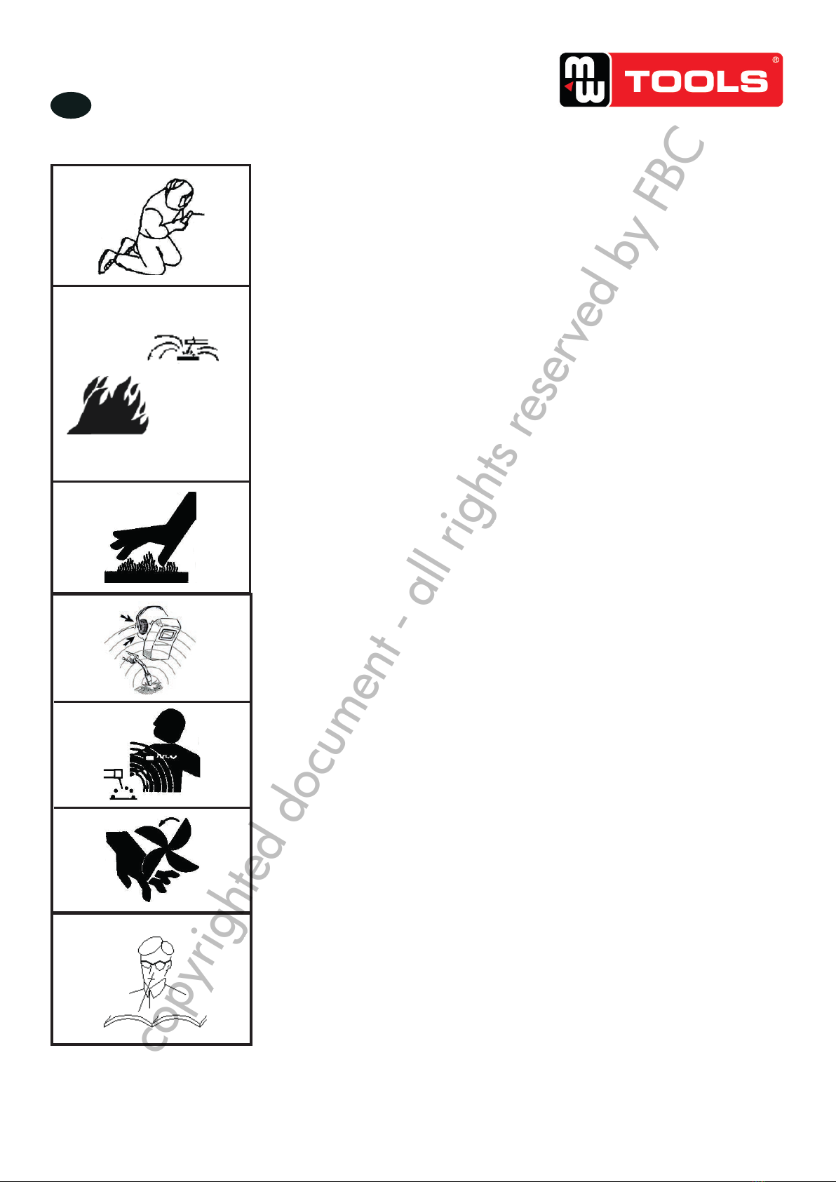
Arc radiation-may hurt your eyes and burn your skin!
Use proper welding mask and wear protective clothing to protect
your eyes and body.
Use proper mask or curtain to protect onlooker from being
injured.
Improper use and operation may result in fire or explosion
Welding spark may result in fire, so please make ensure there
are no inflammables near the welding position, and pay
attention to fire safety.
Ensure there is fire extinguisher nearby, and make sure
someone has been trained to operate the fire extinguisher.
Do not weld closed container.
Do not use this machine for pipe thawing.
Hot workpiece can cause severe scald.
Do not touch hot workpiece with bare hands.
Cool the welding torch for a while after continuously working.
Excessive noise does great harm to people’s hearing.
Wear ear covers or other hearing protectors when welding.
Give warning to onlooker that noise may be potentially
hazardous to hearing.
Magnetic field can make cardiac pacemaker a bit wonky.
People with cardiac pacemaker should stay away from the
welding spot without first talking to a doctor.
Moving parts may injure your body.
Please keep away from moving parts (like fan).
Each door, panel, cover, baffle plate, and protective device the
like should be closed and located correctly.
6/ 25
Z210 SC-A0
Arc radiation-may hurt your eyes and burn your skin!
Use proper welding mask and wear protective clothing to protect
your eyes and body.
Use proper mask or curtain to protect onlooker from being
injured.
Improper use and operation may result in fire or explosion
Welding spark may result in fire, so please make ensure there
are no inflammables near the welding position, and pay
attention to fire safety.
Ensure there is fire extinguisher nearby, and make sure
someone has been trained to operate the fire extinguisher.
Do not weld closed container.
Do not use this machine for pipe thawing.
Hot workpiece can cause severe scald.
Do not touch hot workpiece with bare hands.
Cool the welding torch for a while after continuously working.
Excessive noise does great harm to people’s hearing.
Wear ear covers or other hearing protectors when welding.
Give warning to onlooker that noise may be potentially
hazardous to hearing.
Magnetic field can make cardiac pacemaker a bit wonky.
People with cardiac pacemaker should stay away from the
welding spot without first talking to a doctor.
Moving parts may injure your body.
Please keep away from moving parts (like fan).
Each door, panel, cover, baffle plate, and protective device the
like should be closed and located correctly.
Seek professional support when trouble strikes.
When trouble strikes in installation and operation, please
inspect according to related contents in this manual.
If you still cannot understand fully, or you still cannot solve the
problem, please contact the dealer or the service center of
JASIC to obtain professional support.
2. SYMBOL EXPLANATION
Matters to be noticed in operation
Objects to be specially described and pointed out
More details in CD
It is prohibited to dispose the electrical waste together with other common
wastes. Please protect the environment.
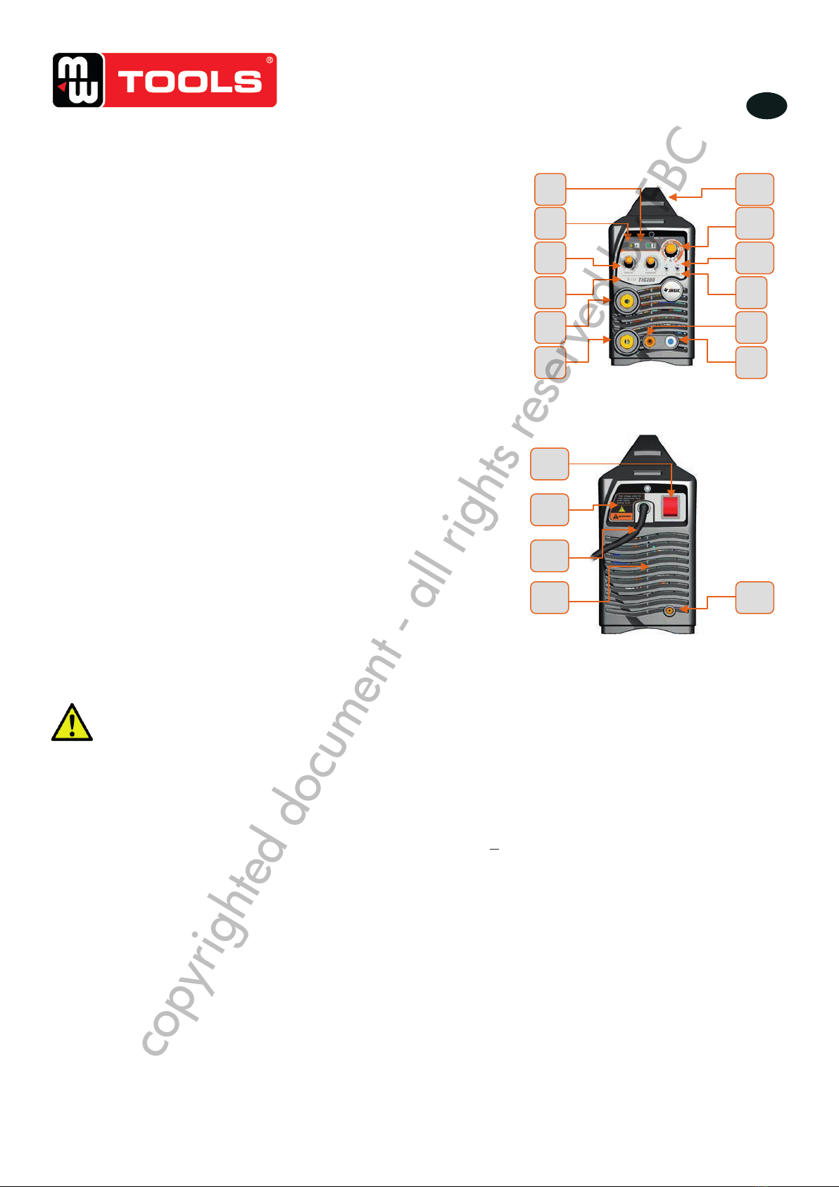
3. PRODUCT OVERVIEW
Unique electric structure and air channel design in this
series of machines can speed up the heat rejection of the
power device as well as improving the duty cycles of the
machines. The unique heat rejection efficiency of the air
channel can effectively prevent the power devices and
control circuits from being damaged by the dust absorbed
by the fan, and the reliability of the machine is greatly
improved thereby.
The whole machine is in form of coherent streamline, the
front and rear panels are naturally integrated via
large-radian transition manner. The front panel and the
rear panel of the machine and the handle are coated with
rubber oil①, so the machine has soft texture, good hand
feeling, and seems warm and pleasant.
①: Not every piece of machine has the same design.
Differences may exist upon customers’ requirements.
Fig. 1
De boogstraling is gevaarlijk voor de ogen en de huid.
• Draag een masker, beschermende kleren en lashandschoenen.
• Gebruik maskers of een scherm om eventueel toeschouwers te beschermen.
Een ongeschikt gebruik van de machine kan een brand of een
ontplofng veroorzaken.
• Vonken kunnen brand veroorzaken. Zorg ervoor dat er geen brandbaar
materiaal in de omgeving liggen.
• Zorg ervoor dat er een brandblusser is in de nabijheid, en dat iemand deze
kan gebruiken.
• Las nooit op een gesloten container.
• Gebruik dit toestel niet om leidingen te ontdooien.
Warme stukken kunnen brandwonden veroorzaken.
• Raak nooit aan warme stukken met blote handen.
• Een koelsysteem is noodzakelijk bij ononderbroken laswerken.
Een te hoog geluidsniveau kan uw gehoor beschadigen.
• Draag een gehoorbescherming tijdens de laswerken.
• Waarschuw de toeschouwers dat het geluid gevaarlijk kan zijn voor hun
gehoor.
Het elektromagnetische veld is gevaarlijk voor mensen met een
pacemaker.
• Mensen die een pacemaker dragen mogen niet bij laswerken blijven zonder
medisch advies.
Bewegende delen kunnen schade veroorzaken.
• Blijf niet in de nabijheid van bewegende delen zoals waaiers.
• Tijdens het lassen moeten de deuren, panelen, deksels en andere
afschermingen gesloten zijn.
In geval van problemen, neem contact op met een vakman.
• Lees het betreffende hoofdstuk van die handleiding in geval van moeilijkheden
bij de installatie of het gebruik van die machine.
• Indien u een probleem met behulp van de handleiding niet kan oplossen,
contacteer de technische dienst van uw verdeler.
copyrighted document - all rights reserved by FBC