MyGate Kit LIBRA User manual

Garage door opener
02/2019

rev02_19

CONTENTS
Do not allow children to play with the automated garage door.
Watch out the door operation and keep the area clear until the door is
completely opened or closed.
Check the automation operation regularly, in particular, check that
cables, springs and fixing brackets do not show signs of wear, damage
or unbalance.
Do not use the automation if repairing or maintenance is needed.
Incorrect assembly or improper use may cause serious injury!
KEEP THIS MANUAL IN A SAFE PLACE
Adapter for overhead doors ...........................................................
E)
F)
Radio transmitter coding ........................................................
G)
Electrical wiring diagram ..........................................................
Manual release ...............................................................................
Maintenance ...................................................................................
Photocell wiring ..............................................................................
Trouble shooting ............................................................................
D)
Rail assembly ............................................................................
Certificate of compliance ................................................................
Disposal ..........................................................................................
A)
Components ..........................................................................
B)
Technical data and main features ..........................................
C)
Safety tips and preliminary checks .........................................
p.1
p.2
p.4
.p.5
Programming ......................................................................... p.8
p.13
p.14
.p.15
.. p.16
... p.18
.. p.19
... p.20
... p.21
p.
... 22
rev02_19

11
Description Quantity
Rail
1
4
6
1
1
1
1
8
1
1
2
1
1
1
3
1
Transmitter
Bent door arm
Door opener
User's manual
Rail mounting bracket
Front wall fixing bracket
Mounting bracket
Support bracket
Hex-head nut and screw 6x80
Pin 8x25
Door fixing bracket
Hex-head tapping screw 6x15
Screw anchor 6x80
Hex-head nut and screw 8x20
Split pin 3x20
Description
Cogwheel
A. COMPONENTS
The kit includes door opener, rail and fittings as shown below:
Quantity
1
Rail (1 m bars)
Door mounting bracket
Chain
Manual release string
Trolley
1
1
3
1
1
rev02_19

22
S
P
B. TECHNICAL DATA AND MAIN FEATURES
Courtesy light
S = Transmitter coding
Adjustments, start-stop, open
Adjustments, start-stop, close
Display
P = Programming
B1. MAIN FUNCTIONS
Door operation:
Motor
Self-diagnosis (see p.20)
Alert system
Power cut
Safety devices
Automatic closing
Maintenance recall
Safety features
Give a start command using the transmitter. The courtesy light
automatically goes on and goes off after 2.5 minutes.
Slowdown in opening and closing ensure maximum noiseless long
lasting operation.
The LED display allows full monitoring on operation and faults.
If door remains opened, an alarm will sound within 10 minutes. The alarm
stops when the door is closed (see p.10)
In case of power failure the door can me manually released (see p.7)
Photocells, safety edges, key switches, emergency push buttons can be
wired (see p.15)
Automatic closing can be adjusted between 30 and 240 seconds.
After 2000 working cycles, an alert sound will be sent to remind the user
maintenance is needed (see p.11)
Obstacle detection in closing and opening (see p.9); safety devices
inputs (p.15). If photocells or safety edges fail, the opener will
automatically set to "dead man" mode.
rev02_19
8m² max
230V 50Hz
1,2 W
2,4m max
3m
3
100 W
700 N
24Vdc
230V 50Hz
1,2 W
3,3m
12m² max
150 W
1100 N
24Vdc
2,7m max
LIBRA LIBRA PLUS
B2. TECHNICAL FEATURES
RAIL (3 cm thick) Ceiling
Minimum gap between rail and ceiling = 1 cm
Main power supply
Motor thrust
Stand-by absorption
Motor power supply
Lift power
Door dimensions
Door height
Rail length
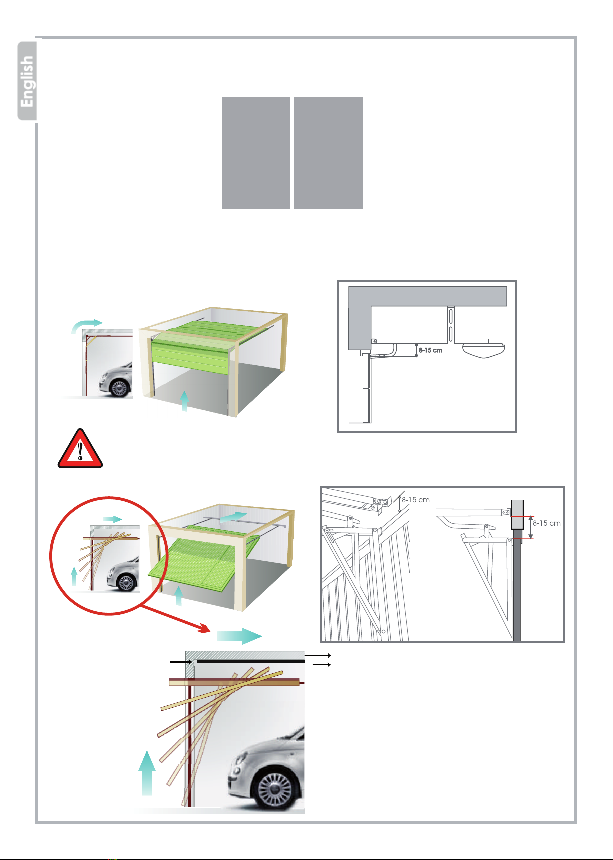
B3. INTENDED USE AND DOOR FEATURES
LIBRA opener is intended for sectional doors application.
In case of counterweighted balanced doors, ARC adapter bracket is needed
(available for sale accessory)
rev02_19
4
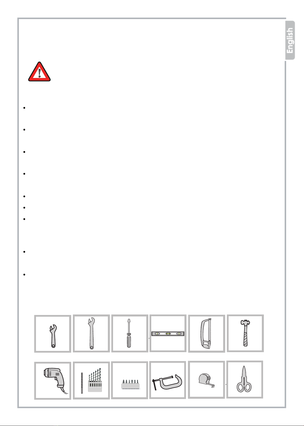
C. SAFETY TIPS AND PRELIMINARY CHECKS
Before installing the automation, remove all unnecessary packaging and
accessories;
Check that door opens and closes easily and that mechanical parts are in
good condition and correctly balanced;
When installing make sure the manual release string is left less than 1,8 m
length;
Fixed start commands must be within the door area but safely far from
moving parts, at minimum height of 1,5 m from ground.
Visible permanent warnings of entrapment must be fitted.
The emergency release system must be clearly permanently visible;
Once installation is complete, make sure the opener is properly adjusted
and reverses during closing if an obstacle is encountered at least 40 mm
from ground;
Make sure door does not obstruct public sidewalks or roads during
operation;
Once installation is completed, make sure the opener stops during opening
if an obstacle is encountered. Put a 20 kg load in the centre of the door on
the lower side to test the reaction of the system.
CAREFULLY FOLLOW MOUNTING INSTRUCTIONS.
AN IMPROPER INSTALLATION MAY CAUSE SEVERE INJURIES!
rev02_19
5
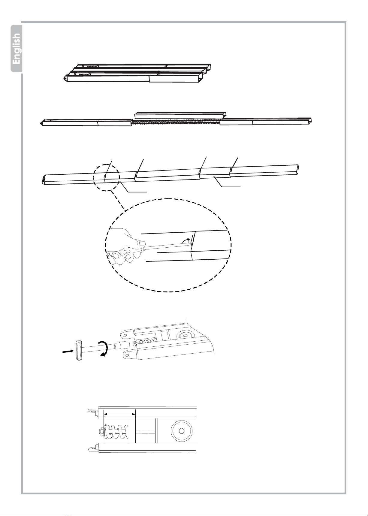
D. RAIL ASSEMBLY
1) Open the carton box
2) Lay the rail as shown below
3) Fit the joint keeping the two retainers at sight
RetainerRetainer RetainerRetainer
Joint Joint
4) Use a 10 hex wrench to adjust the chain tension
5) Adjust the distance as indicated
rev02_19
36-38 mm
1
2
3
4
1
23
4
5
6
7
8
9
910
11
13
6
6
6
613
14
12
12
12 12
6
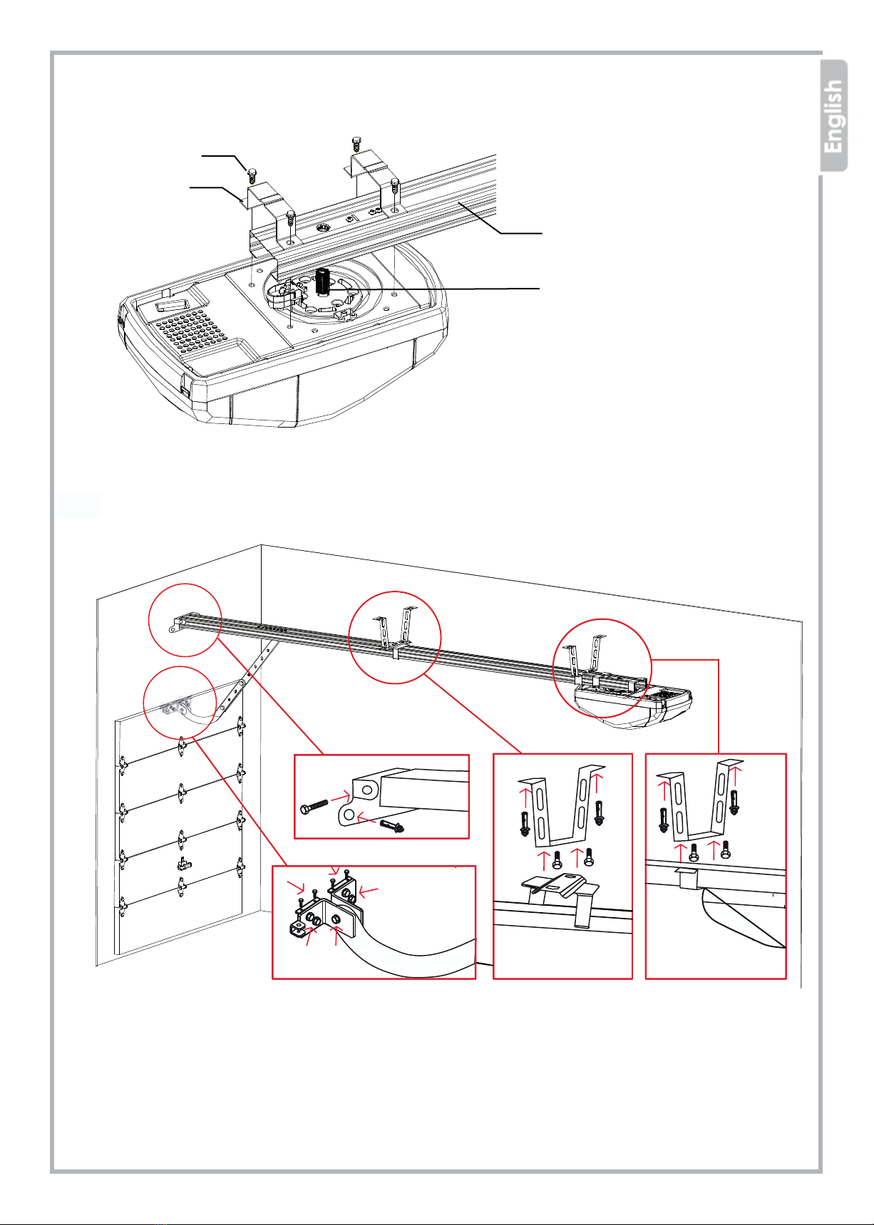
1 Self-tapping screws 6x15
2 Rail mounting bracket
3 Rail
4 Cogwheel
9 Self-tapping screw 6x15
10 Bent arm
11 Support bracket
12 Screw 8x20
13 Gearmotor mounting bracket
14 Rail mounting bracket
1 Wall
2 Door
3 Wall bracket
4 Screw 6x80
5 Rail
6 Screw anchor
7 Door fixing bracket
8 Hinge pin 8x25
D1. GEARMOTOR AND RAIL MOUNTING
D2. GEARMOTOR AND RAIL FIXING
rev02_19

7
D3. MANUAL OPENING
IF POWER FAILURE OCCURS:
1 When door is in CLOSING POSITION:
Pull the string and unlock the joint, so the door can easily lift.
2 When door is in OPENING POSITION:
Pull the string once to allow the door to close.
String
Clutch joint
Rail
WHEN POWER RECOVERS
Give a start command using the transmitter or other fixed
commands: the trolley clutch engages automatically.
D4. MANUAL RELEASE FROM OUTSIDE
If the garage has no pedestrian entry door, it's possible to fit an external release system to the
existing garage door handle. The MLIR07 release kit can be purchased separately as an
optional accessory (see page 16)
rev02_19
This manual suits for next models
1
Table of contents
Other MyGate Gate Opener manuals


