Calimet CM6-ACFP User manual

1
PRODUCT SPECS
WARNING
To reduce the risk of INJURY or DEATH:
•Never let children operate the gate or play around the gate. Keep the remote control away
from children.
•Always keep people and objects away from the gate. Cars, people, and other objects should
never enter when the gate is closing.
•Test gate operator monthly. The gate must reverse when it comes in contact with a solid
object, or stop when an object activates the non-contact sensors. After adjusting the force or
travel limit, re-test the gate operator. Failure to maintain the gate operator properly can
increase the risk of injury or death.
•Use the emergency release only when the gate is not moving.
•Keep the gate properly maintained. Read the owner's manual on how to maintain your gate.
Have a certified service technician make repairs or install gate operator hardware.
•The gate entrance should be used for vehicles only. Pedestrians should use a seperate entrance.
•Keep these instructions.
Voltage Input: 110V
Maximum Output Current: 15 amp, Fuse: AC 110V 15 amp
Remote Control Distance: >150 Feet (50 meters)
Maximum Gate Weight: 1000 lbs
Maximum Gate Length: 18 Feet
•Verify this operator is proper for the type and size of gate.
•Make sure the gate has been properly installed and slides freely in both directions. Repair
or replace all worn or damaged gate hardware prior to installation.
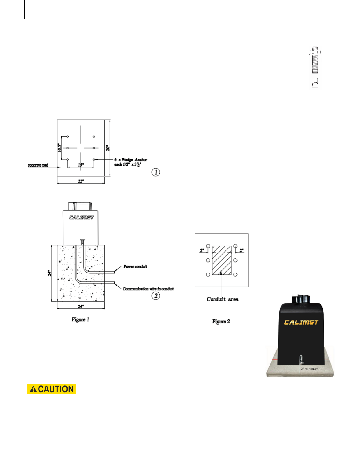
Product Specs
LANGUAGES
To download this user manual in a different language, visit calimetco.com/manuals
Para descargar este manual de usuario en otro idioma, visite calimetco.com/manuals
下载其他语言版本用户手册,请访问 calimetco.com/manuals

Installation
1. Lay out position of 6 wedge anchors by measuring clearance between anchors
and inside edge of gate. Figure 1
2. Install underground conduits in area for conduits. Figure 2 Wedge Anchor
Step 1: Installing the Base
The base, also known as a pad is a raised platform. We recommend using a concrete base.
1/2" x 3 1/2"
2
Contact local underground utility locating companies before digging more than 12 inches deep to
avoid damaging underground power, gas or other utility lines.
Size of concrete base
A minimum of 2" on each side of the operator is recommended.

Step 2: Door arm installation
Figure 3
After you're satisfied with testing the arm in the full open and closed positions,
weld gate
bracket and arm.
Figure 4
A. Should be at least 1/4 the gate length. NOTE: Uphill or heavy gates should be at least 1/3 gate
length.
B.
C.
14" minimum for open gate clearance (2" thick gate)
27" distance
D&E. Arm should be 90° from gate when open and in the straight "locked". D=L*0.6, E=L*0.4
Installation
3

A. DO NOT allow the arm to touch the gate operator's hood when the gate is in the open
position. Too much stress is put on the arm in this position during gate operation.
Figure 6
A. Preferred arm position is 90° from the open gate.
B.
Distance between door and machine: 2" min
Installation
Figure 5
C.
4
NOTE: If dimension between open gate and wall is 20" to 32" then compact installation is
necessary. (See Figure 7)

Figure 7
Support bar should be installed at the gate bracket height across the entire gate to keep the
gate pickets from bending.
Installation
5

Figure 8
Figure 9
1. MUST use UL approved power wires, power wires MUST have minimum capacity for 15
amp current.
2. All operators MUST be properly grounded in order to prevent an electrical charge. Must
use a dedicated circuit for power supply.
3. When the power is connected, turn operator power switch to ON position.
Installation
6
Step 3: Connecting the Power

Step 4: Open Position
Installation
7
Open Direction
Choose whether your gate opens left or right.
Dip Switch #6 (Figure 10) on the bottom of the gate operator circuit board
controls the open direction.
On = opens right, Off = opens left
Figure 10
Step 5: Installing the Photo Eye
1. Plug the photo eye cable to the back of the gate opener,
behind the circuit board, Figure 11
2. Press the reset button on the gate operator control board.
3. Mount the photo eye on the stationary part of your gate or a post next
to your gate, about 21" from the ground.
4. Press the orange button on the photo eye to turn on the infrared beam.
5. Mount the reflector to the opposite side. Make sure the infrared beam hits
inside the circle of the reflector. Figure 12
6. Press the orange button on the photo eye to turn off the infrared beam.
Plug photo eye
cable here
Figure 11
Figure 12
Infrared beam
inside circle
Youtube
Youtube video with more details on how to install the photo eye: https://youtu.be/F7NpB9W_OMY

Installation
Step 6: Gate Travel Limit
This controls the position of where the gate stops when it opens and closes.
1. Use a screwdriver to loosen the nails on the top and bottom limit cams
2. Turn left or right on both limit cams to adjust the position of where the gate opens and closes. Figure 9
TIP: Use the OPEN, CLOSE, STOP buttons on the gate operator circuit board for faster testing
3. Use the screwdriver and screw back in the limit cam nails
Youtube
More detail on travel limit programming: https://youtu.be/_DeVM5dgZPs
Finished! You are now finished installing your gate operator.
Figure 13
8

9
Figure 14
Opening the gate
1. Disconnect power.
2.
Push release pedal downward and move slightly to the right until it is locked in.
3. Hold and push gate to desired direction.
Reset the Pedal
Reset the pedal only when the operator doesn't work while using the remote control.
1.
Push the pedal downward from locked position and slightly move to the left.
2. Allow the pedal rise up to the reset position and release the pedal.
Features
EMERGENCY RELEASE
The emergency release allows you to open the gate manually, such as in cases where there is a
power outage and there is no electricity.

Figure 15
Features
Safety and Exit Loop
This is an optional step. If you wish to install a exit loop detector, see figure 15 for the
position of the safety and exit loops.
Entrapment Protection
10

Features
Dual Gates Setup - Master/Slave
This setup is for dual swing gates. A single button press of the remote control can open both gates.
This requires 2 swing gate operators. One gate operator is the "Master", and the other is the "Slave".
1. On the SLAVE gate operator circuit board, set dip switch #5 to ON (Figure 1).
2. Press the reset button on the SLAVE gate operator circuit board.
3. A 20 awg cable (or higher gauge) with two conductors is required.
A. Locate the green terminal (Figure 2) on the bottom of the circuit board with the words DATA- and DATA+.
B. Use a flathead screwdriver to release the 2 locks on the top of the green terminal.
C. For conductor 1, connect the DATA+ on the MASTER circuit board to the DATA+ on the SLAVE circuit board.
D. For conductor 2, connect the DATA- on the MASTER circuit board to the DATA- on the SLAVE circuit board.
E. Use the flathead screwdriver to close the two locks on the top of the green terminal.
4. Place the cable underground in an electrical conduit.
5. Make sure all remote controls, photosensors, loop detectors, and any other accessories are installed
on the MASTER gate operator, and not the SLAVE. The setup is now complete.
Figure 2
Figure 1
11

Figure 16
Features
Control Board Layout
This is a picture of the control board. Use this for reference.
Youtube
Circuit board Programming Guide: https://youtu.be/_7iBuKr1ZtY
12

13
Connecting Additional Remote Controls
Figure 17
There are two ways to connect your remote control: Study Mode & Numeric Mode.
Study mode can fit up to 60 different remote controls.
Connect using Study Mode On your gate operator circuit board, look for the study key. Press
and hold the button on the remote control. Press and hold the study key for 1.5-2 seconds.
Done, the remote is now connected to the gate opener.
Removing existing remote controls Press the STUDY key on the gate operator circuit
board and hold for 8 seconds. Done. All remote controls are now removed.
Numeric Mode
A.
On your circuit board, turn the SW9 key to the ON position.
B.
Unscrew the back of the remote control to gain access to the control board. You
should see 1-8 dip switches. Each switch has 3 positions: up, middle, bottom. Flip
these 1-8 switches to any position you'd like.
C. On the gate opener control board, look for the same 1-8 dip switches, and set the same
combination as you did on the remote.
D. Finished.
Note:
On switch SW10, KEY 1 and KEY 2 are used for the 2-button model of remote
controls. Note: if KEY 1 code was set with BUTTON ONE on remote control; KEY 1 will NOT
work with BUTTON TWO on the remote control.
By default, the remote controls are already connected to the gate operator. You do not need
to do any of the following steps unless you are adding more remote controls.
Study Mode
Youtube
Youtube video that explains more on remote control programming:
https://youtu.be/QfT6O4apTI8
Features

Use Infrared Control
Figure 19
Follow infrared control instruction to connect power. Common wire is connected to Common
pole, signal wire is connected to OPEN or CLOSE pole.
14
Features
Figure 18 DIP switch
1. CL-DELAY: Gate Closing delay, switch to ON position, turn timer to 1- 6 seconds.
2.TIMER: 1-60 Timer: Auto activated to close gate upon set time ( 1~ 60 seconds).
3. OSC: Remote control priority. Allow remote control to direct gate movement whenever gate is
moving in any direction. Use first signal to stop gate, use second signal to move gate to opposite
direction.
4. 1 PASS: Anti-tailgating system. It corresponds to underground safety loop. After the vehicle has
cleared safe loop outside of property, gate will start to close immediately without opening to limit,
when ON is selected. If second vehicle across loop at this time, gate will stop. The second vehicle
must get off the loop and then gate will continue to close completely.
5. SLAVE: Secondary operator activation
6. OPEB L/R: Choose gate open direction Left or Right.
DIP Switch Features

Figure 20
15
Features
External Receiver
External connectors are installed on the rear side of mainboard protector box.

Remote Control & Timer Delay Closing
Figure 23
A. Remote Control delay closing
1. Choose time delay to activate operator between 0~6 seconds by turning knob on DELAY
16
Features
Figure 22
2. CLOSE Sensitivity: Increase/decrease amount of force by turning knob clockwise/
counter clockwise. This is the fourth blue knob on the circuit board. Figure 22, left.
1. OPEN Sensitivity: Increase/decrease amount of force by turning knob clockwise/
counter clockwise. This is the third blue knob in the circuit board. Figure 22, left.
3. Test device sensitivity every 6 months.
Sensitivity
The sensitivity has to do with the weight of the gate, and also other factors. A heavier gate will require
less sensitivity, and a lighter gate will require more sensitivity.
If a gate is too sensitive, the gate may stop or reverse by itself. It it's not sensitive enough, it might
not stop or reverse.
1. On your gate operator circuit board in the bottom, turn Dip Switch #2 to the ON
position. Figure 24
2. On the gate operator circuit board, adjust the delay by turning the second blue knob
from 0-60 seconds. Figure 25
Auto Close
This allows your gate to automatically close after opening it.
Figure 24 Figure 25

9949 Hayward Way
South El Monte, CA 91733
Tel: 626-452-9009 Alternate: 626-482-3066 Fax: 626-452-9010
Email: [email protected]
www.calimetco.com
Table of contents
Other Calimet Gate Opener manuals

Calimet
Calimet CM-5-ACFP User manual

Calimet
Calimet CM9-975 User manual

Calimet
Calimet CM3-DCNB User manual

Calimet
Calimet CM7-DCNB User manual

Calimet
Calimet CM-5-ACFP User manual

Calimet
Calimet CM3 Installation instructions

Calimet
Calimet CM3-ACFP User manual

Calimet
Calimet CM7-DCFP User manual

Calimet
Calimet CM6 Installation instructions

Calimet
Calimet CM6-DCFP User manual
Popular Gate Opener manuals by other brands

SEA
SEA SCUTI installation instructions

Serai
Serai 30F D installation guide

BFT
BFT VIRGO Installation and user manual

Erreka
Erreka VIVO-M201 Quick installation and programming guide

Devanco
Devanco BCSI Technical manual installation maintenance

Cardin Elettronica
Cardin Elettronica 200/BL202 instruction manual