Neptun Compact 950 Guide
1
Betriebsanleitung GSA Compact 950/1200 Edelstahl V.20181129
Montage- und Betriebsanleitung
Pflegetipps
Gegenstromanlage
Jet stream
Compact 950 / 1200
Edelstahl
GSA 950-1200 Edelstahl_Layo t 1 a4 14.12.18 08:59 Seite 1

2
Betriebsanleitung GSA Compact 950/1200 Edelstahl V.20181129
Inhaltsverzeichnis
Montage Einbausatz .......................................................................................................................
Montage der Basiseinheit ...............................................................................................................
Montage der Einlaufblende .............................................................................................................
Zur Beachtung für bauausführende Firmen ....................................................................................
Technische Daten der Pumpe .........................................................................................................
Fehler / Ursache / Behebung ..........................................................................................................
Betriebshinweise für den Endverbraucher ......................................................................................
Stückliste Einbausatz ......................................................................................................................
Stückliste Basiseinheit ....................................................................................................................
Montageabbildungen ......................................................................................................................
Schaltpläne .....................................................................................................................................
Bedienung .......................................................................................................................................
Empfohlenes Zubehör .....................................................................................................................
3
3
4
4-5
5
6
7
8
7
20
21
21
19
mounting installation kit ..................................................................................................................
mounting of the base unit ...............................................................................................................
installation of the inlet aperture .......................................................................................................
precautions for building companies ...............................................................................................
technical data of the pump .............................................................................................................
errors/ cause / removal ...................................................................................................................
operating instructions for the end user ...........................................................................................
inventory installation kit ..................................................................................................................
inventory base unit .........................................................................................................................
mounting illustration ........................................................................................................................
schematics ......................................................................................................................................
operation .........................................................................................................................................
recommended equipment ..............................................................................................................
9
9
10
10
11
12
13
8
8
20
21
21
19
Contents
Die in diesem Dokument gegeben Hinweise und Richtlinien entsprechen dem Stand der Technik und sind kein Er-
satz für eine Beratung bzw. deren Ausführung durch Schwimmbadfachhandel bzw. die entsprechenden Bauor-
gane und Baufirmen unter Einhaltung der geltenden Bauvorschriften. (Stand 10/2002).
Im Falle von Reklamationen bitte die Kontrollnummer und eine Kopie des Kaufbeleges beilegen.
The instructions and guidelines given in this document correspond to the state of technology and aren`t any repla-
cement for a consultation or the carrying out by pool specialist shops or the corresponding building divisions and
construction companies in compliance of current building regulations. In the case of complaint, please enclose
the check number and a copy of the invoice.
GSA 950-1200 Edelstahl_Layo t 1 a4 14.12.18 08:59 Seite 2
3
Betriebsanleitung GSA Compact 950/1200 Edelstahl V.20181012
Bitte lesen Sie diese Betriebsanleitung sorgfältig und vollständig, bevor Sie mit
den Arbeiten beginnen. Etwaige Fehler sind nur mehr unter erheblichem Aufwand oder gar
Montage Einbausatz:
Achtung: Die korrekte Montage des Einbausatzes ist Voraussetzung für die einwandfreie Funktion
der NEPTUN Gegenstromanlage. Bei Rückfragen sollten Sie Ihren Schwimmbadfachhändler kon-
taktieren. Weitere Daten und Unterlagen finden Sie unter www.neptun-int.com.
Die korrekte Einbauhöhe des Einbausatzes ersehen Sie in Abb. 1. Die Erdungsschraube (s. Abb.
2) muss sich an der Beckenaußenseite (Schacht) befinden und zur Oberseite (Wasseroberfläche)
weisen. Die beiden großen Durchlässe (Einströmung und Absaugung) sind unbedingt lotrecht (im
rechten Winkel zur Bodenplatte) anzubringen, nur dadurch ist eine korrekte Montage der Einlauf-
blende bzw. des Pumpenaggregates möglich.
Achten Sie darauf, den Einbauteil und die Gewinde für die spätere Flansch- bzw. Pumpenwinkel-
montage während der Betonarbeiten nicht zu verschmutzen (Bauschutz verwenden). Bei Folien-
verlegung Flachdichtung am Einbautopf anbringen, dann die Folie und Flansch mittels 4
Schrauben (Stückliste 4) fixieren.
Beachten Sie Abb. 1: Nur die mit X gekennzeichneten Gewinde verwenden.
● Die mit diesem Zeichen markierten Gewinde dienen zur Aufnahme der 4 Distanz
schrauben (Stückliste 5) welche zur Montage der Einlaufblende benötigt werden.
Montage Basiseinheit:
1. Beginnen Sie mit der Anbringung der Durchführungen für den Ein-Aus-Taster und den Luftan-
schluss (Abb. 1). Der Luftanschluss (Stückliste 2) ist mit dem Schlauch nach außen zu montieren,
so dass innen der Luftzufuhrschlauch (Stückliste 11) zur Einlaufblende (Stückliste 13) später an-
gesteckt werden kann. Bei den Durchführungen ist darauf zu achten, dass die Dichtung an der
Beckenaußenseite liegt. Die Gewindeteile der Durchführungen sind von der Beckenaußenseite
nach innen durchzustecken und mit den dazugehörigen Muttern zu fixieren. Beachten Sie Abb. 3.
2. Bereiten Sie das Pumpenaggregat vor und bringen Sie die Flachdichtung (Stückliste 6) am
Pumpenaggregat vorne an und schieben Sie die Pumpe durch die vorgesehenen Durchlässe.
Abb. 5.
3. Stecken Sie den Pumpenflansch (Stückliste 8) von der Beckeninnenseite auf die hereinragen-
den Schrauben bzw. Stutzen und fixieren Sie dieses mittels 6 Muttern und Beilagscheiben (Stück-
liste 7).
4. Luftschlauch 45 cm mit Feder (Stückliste 9) „überziehen“ (Knickschutz) und am Einbausatz bei
der Durchführung für den Ein-Aus-Schalter anbringen. Nun die Klemmhülse (kurz/breit) über den
Schlauch schieben und den Schlauch mittels Klemmhülse fixieren. Den Luftzufuhrschlauch
(Stückliste 11) ebenfalls an der dafür vorgesehenen Durchführung am Einbausatz anbringen. Abb.
6
GSA 950-1200 Edelstahl_Layo t 1 a4 14.12.18 08:59 Seite 3

4
Betriebsanleitung GSA Compact 950/1200 Edelstahl V.20181129
5. Verschrauben Sie nun die Pumpe mit dem Pumpenwinkel mit Hilfe der Schrauben und Beilag-
scheiben (Stückliste 12).
6. Verbinden Sie die Durchführung des Ein-Aus-Tasters mit Hilfe des Pneumatik-Schlauchs 2,5 m
(Stückliste 10) mit dem Schaltkasten (Stückliste 16).
Achtung dieser Schlauch sollte nicht verlängert werden, da ansonsten ein einwandfreies
Ein- und Ausschalten nicht mehr gewährleistet werden kann.
Montage der Einlaufblende:
1. Schrauben Sie die 4 Distanzschrauben (Stückliste 5 Einbausatz) in die dafür vorgesehenen Ge-
winde. Beachten Sie hierzu Abb. 1.
Gekennzeichnet ●
2. Verbinden Sie nun die Leitung für die Luftzufuhr bzw. für den Ein-Aus-Schalter (Achtung: Feder
muss am Schlauch sein!) mit den entsprechenden Anschlüssen an der Einlaufblende. Abb. 7. Ver-
wenden Sie bei der Fixierung des Luftschlauches an der Einlaufblende die Klemmhülse
(lang/dünn) und verfahren Sie wie bei der Montage der Basiseinheit Punkt 5.
3. Die Einlaufblende einsetzen und mittels 4 Schrauben (Stückliste 14) fixieren.
4. Soll ein Rundhaltebügel montiert werden, so ersetzt dieser den Flansch.
Zur Beachtung für bauausführende Firmen:
Der Pumpenschacht muss ein Mindestmaß von 60 x 60 cm und eine Mindesttiefe von 100 cm
aufweisen. Weiters muss eine ausreichende Entlüftung sowie eine Ablaufmöglichkeit für eventuell
austretendes Wasser vorhanden sein.
Zum Abdichten von Kunststoffgewinden ist ausschließlich Teflonband zu verwenden.
Sämtliche Anlagenteile sind so zu montieren, dass diese spannungsfrei bzw. frei von Verschmut-
zungen sind. Insbesondere der Sitz sämtlicher O-Ringe, Überwurfmuttern etc. ist dahingehend zu
überprüfen.
Die Pumpe darf niemals trockenlaufen (dh ohne Wasser), da ansonsten die Gleitringdichtung be-
schädigt wird (Garantieverlust).
Die Benutzung in und an Schwimmbecken bzw. Gartenteichen ist nur zulässig, wenn diese nach
lokalen gesetzlichen Bestimmungen errichtet sind. Kontaktieren Sie diesbezüglich Ihren Neptun-
Fachmann bzw. die lokale Baubehörde.
Belegungsplan/Schaltplan Abb. 9/10
GSA 950-1200 Edelstahl_Layo t 1 a4 14.12.18 08:59 Seite 4

5
Betriebsanleitung GSA Compact 950/1200 Edelstahl V.20181129
Technische Daten der Pumpen
Basiseinheit Compact 950 Compact 1200
Spannung 230 - 400 V / 50 Hz 230 - 400 V / 50 Hz
Aufnahme in KW 2,73 3,36
Fördermenge l/min. 850 980
Vorsicherung 16 A, träge 16 A, träge
Motorschutz ab Werk 4,6 A 6,1 A
Schutzklasse IP X5 IP X5
Es sind die Vorschriften nach ÖVE (VDE), sowie die örtlichen EVU bei der Installation der Anlage
unbedingt zu beachten. Die Installation darf ausschließlich von einem konz. Elektriker durchge-
führt werden.
In der Netzleitung muss eine allpolige Trenneinrichtung mit einer Kontaktöffnung von mind. 3 mm
vorhanden sein.
In der Netzleitung ist ein Fehlerstromschutzschalter mit einem Nennfehlerstrom von <= 30 mA
vorzusehen.
Achtung: Auf Motordrehrichtung achten. (Drehrichtungspfeil)
Das Schaltgerät (Stückliste 16) ist an einem gut zugänglichen, trockenen Ort zu installieren.
Das Luftansaugventil muss sich über dem Niveau der Wasseroberfläche befinden. Im Schacht ist
ein ausreichend dimensionierte Bodenablauf vorzusehen.
GSA 950-1200 Edelstahl_Layo t 1 a4 14.12.18 08:59 Seite 5

6
Betriebsanleitung GSA Compact 950/1200 Edelstahl V.20181129
Fehler/Ursache/Behebung
Pumpe ist sehr laut und bringt nicht die Normalleistung
Falsche Drehrichtung des Motors Motor umpolen durch Vertauschen der
Phasen (400V)
Pumpe ist sehr laut und bringt volle Leistung
Motorhaube streift/ist locker Lüfterhaube ordnungsgemäß befestigen
Pumpe läuft nicht bzw. schwer und langsam an
Eine Phase fehlt Zuleitung ändern
Beim Einschalten fallen die Sicherungen
Flansche Sicherungen Sicherung 16 A träge verwenden
Motorschutzschalter löst sich aus
Falsche Einstellung Richtigen Stromwert + 10 % einstellen
Pumpe lässt sich vom Becken aus nicht schalten
Schaltschlauch geknickt oder
verklemmt / Schlauch zu lang
Sicherungen / Stromzufuhr
Motorschutzschalter
Prüfen ob Pumpe vom Schaltkasten aus schaltbar ist.
Schlauch wenn nötig kürzen,
Sicherungen, Stromzufuhr prüfen.
Motorschutzschalter testen.
GSA 950-1200 Edelstahl_Layo t 1 a4 14.12.18 08:59 Seite 6
7
Betriebsanleitung GSA Compact 950/1200 Edelstahl V.20181129
Betriebshinweise für den Endverbraucher:
Pumpe Ein-/Ausschalten (Abb. 11):
Durch Drücken des Druckknopfes Pos. 1 wird der Pneumatikschalter betätigt und die Pumpe
geht in Betrieb. Nochmaliges Drücken schaltet die Pumpe aus.
Strahlrichtung und Strahlregulierung (Abb. 11):
Die Strahlrichtung kann durch die allseitig schwenkbare Düse (Pos. 2) festgelegt werden. Durch
Drehen derselben stellen Sie den Wasserstrahl stärker bzw. schwächer.
Luftregulierung und Massage (Abb. 11)
Durch Drehen des Ringes (Pos. 3), welcher auf der Düse angebracht ist, wird die Luftzufuhr
schwächer bzw. stärker.
Gegenstromschwimmen:
Düse so schwenken, dass die Wasserschicht unmittelbar unter der Wasseroberfläche in starke
Strömung versetzt wird.
Verwendung des Massage-Zubehörs (Abb. 12)
Vor dem Anbringen oder Entfernen ist die Gegenstromanlage abzuschalten.
Zum Anbringen der Massage-Einheit ziehen Sie die Schiebemuffe (Pos. 5) zurück und schieben
die Schlauchkupplung in dies Düse (Pos. 2). Drücken Sie nun die Schiebemuffe gegen die Düse
und ziehen Sie den Schlauch (Pos. 6) zurück. Die Schlauchkupplung ist verriegelt.
Zum Abkuppeln drücken Sie den Schlauch (Pos. 6) gegen die Schiebemuffe (Pos. 5), Schiebe-
muffe fassen und herausziehen.
ACHTUNG:
Massagezubehör nicht näher als 30 cm an den Körper halten, optimaler Massageeffekt bei voller
Durchflussleistung und geeignetem Abstand.
Überwinterung:
Wasser bis unterhalb des Düsenblocks ablassen. Pumpe mit Hilfe der Entleerungsschraube an
der Vorderseite der Pumpe entleeren. Erst nach Ende der Frostgefahr Entleerungsschraube wie-
der eindrehen.
GSA 950-1200 Edelstahl_Layo t 1 a4 14.12.18 08:59 Seite 7
8
Betriebsanleitung GSA Compact 950/1200 Edelstahl V.20181129
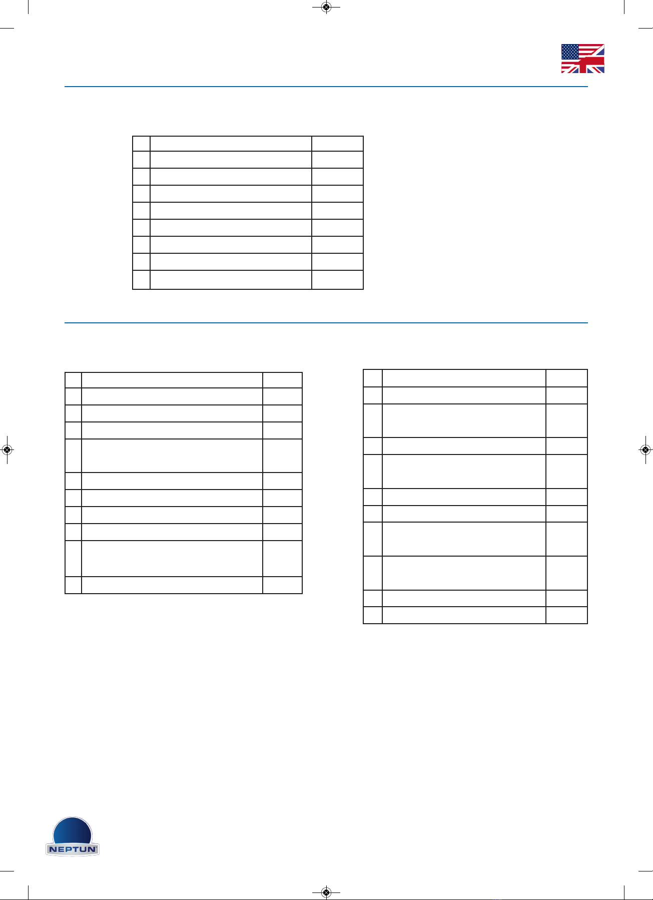
Stückliste Einbausatz
Siehe Bild 1
Stückliste Basiseinheit Compact 950 / 1200
Siehe Bild 2
Nr. Bezeichnung Anzahl
1 Einbautopf 1
2 Dichtung selbstklebend 1
3 Flansch 1
4 Linsenkopfschraube M 6 x 16 4
5 Distanzschraube M 6 x 16 4
6 Bauschutz 1
7 Kontrollnummer 1
8 Betriebsanleitung 1
Nr. Bezeichnung Anzahl
1 Durchführung Ein-Aus-Taster kpl. 1
2 Durchführung Luftanschluss kpl. 1
3 Pumpenwinkel 2
4Sechskantschraube M 10 x 12
+ Beilagscheibe
4
5 Pumpenlagerblock 4
6 Pumpenflachdichtung 1
7 Mutter M 8 + Beilagscheibe 10
8 Pumpenflansch 1
9PN-Schlauch 50 cm
+ Knickschutz (Feder)
1
10 PN-Schlauch 250 cm 1
Nr. Bezeichnung Anzahl
11 Luftzufuhrschlauch 50 cm 1
12 Sechskantschraube M 8 x 10
+ Beilagscheibe 4
13 Einlaufblende kpl. 1
14 Linsenkopfschrauben M 6 x
16 4
15 Pumpe C 950 oder C 1200 1
16 Steuergerät kpl. 1
17 Klemmhülse (kurz/breit) o.
Abb. 1
18 Klemmhülse (lang/dünn) o.
Abb. 1
19 Kontrollnummer o. Abb. 1
20 Betriebsanleitung o. Abb. 1
GSA 950-1200 Edelstahl_Layo t 1 a4 14.12.18 08:59 Seite 8
9
Betriebsanleitung GSA Compact 950/1200 Edelstahl V.20181129
Mounting installation kit
Attention: The correct installation of the installation kit is a prerequisite for the proper functioning
of the NEPTUN jet stream. For further information, please contact your pool specialist supplier or
visit www.neptun-int.com to ask for more data or further information.
The correct installation height of the installation kit is indicated in fig. 1 The earthing screw (see
fig. 2) must be located on the outside of the pool (shaft) and must point to the upper side (water
surface). The two major opening (inflow and extraction) must be mounted necessarily perpendi-
cular (at a right angle to the base plate). That`s the only way a correct mounting of the inlet aper-
ture and the pumping set is possible. Make sure not to soil the mounting parts and the threads
for the later flange or pump angle assembly during concrete work (use building protection). When
laying the film mount the flat gasket on the built-in pot, then fix the film and flange with 4 screws
(bill 4). Note fig.1: Only use the with X marked threads.
Threads marked with this symbol are used to take up the 4 distance screws
(list of parts 5) which are required for the mounting of the inlet aperture.
Mounting the base unit:
1.Start with the installation of the implementations for the on-off button and the air connection
(fig. 1). The air connection (list of parts 2) is to be mounted with the hose to the outside, so that
the air supply hose (list of parts 11) can be later attached to the inlet aperture (list of parts 13) in
the inside. Concerning the implementations make sure that the seal is on the outside of the pool.
The threaded parts of the bushings must be put through from the outside of the pool to the in-
side and secured with the matching nuts. Note fig. 3
2. Then mount the two pump angles (bill 3) with the 4 screws and washers (list of parts 4). Note fi-
gure 4
3. Prepare the pump unit and mount the 4 bearing blocks ( list of parts 5) with 4 nuts and washers
(list of parts 7). Mount the flat gasket (list of parts 6) at the front oft he pump unit and slide the
pump on the angles through the provided openings. fig 5
4. Put the pump flange (list of parts 8) from the inside of the pool to the protruding screws or
clips, and fix it with 6 nuts and washers (list of parts 7).
5. „Overdraft“ the 45 cm air hose with the spring (list of parts 9) (antikink) and attach it at the im-
plementation of the on-off switch at the installation kit. Then push the clamping collet (short/wide)
over the hose and fix the hose with the clamping collet. Mount the air supply hose (list of parts
11) at the provided implementation of the installation kit. fig. 6
6. Then bolt the pump with the pump angle with the help of the screws and
washers ( list of parts 12).
7. Connect the implementation of the on-off switch with the help of the pneumatic hose 2.5 m (list
GSA 950-1200 Edelstahl_Layo t 1 a4 14.12.18 08:59 Seite 9
10
Betriebsanleitung GSA Compact 950/1200 Edelstahl V.20181129
of parts 10) with the control box (list of parts 16). Attention: this hose should not be extended, be-
cause otherwise a perfect on and off switch can not be guaranteed.
Installation of the inlet aperture:
1. Screw the 4 distance screws (list of parts 5 installation kit) in the appropriate thread. Note the-
refore fig. 1
marked with
2. Then connect the line for the air supply or for the on-off switch (Attention: Spring must be on
the hose) with the appropriate connections on the inlet aperture. fig 7. Use the clamping collet
(long/thin) to fix the air hose to the inlet aperture and act like in mounting the base unit point 5.
3. Insert the inlet aperture and fix it using 4 screws (list of parts 14).
4. If a round retainer is mounted, it replaces the flange.
Precautions for building companies
The pump shaft must have a minimum of 60 cm x 60 cm and a minimum depth of 100 cm. Fur-
thermore there must be a sufficient ventilation as well as a drain possibility for any leakage of
water.
For sealing the plastic thread exclusively a Teflon tape must be used.
All system components must be mounted in the way that they are voltage free and free of conta-
mination. In particular, the seat of all the o-rings, union nuts, etc. must be checked to that effect.
The pump must never run dry (which means without water), because otherwise the mechanical
seal will be damaged (loss of warranty).
The use in and around swimming pools or garden ponds is only permitted if they are built accor-
ding to local statutory regulations. In this regard please contact your Neptun expert or the local
bulding department.
assignment plan/ wiring diagram for Compact 950 fig. 8/9/10
There are rules necessarily to be observed by ÖVE (VDE), as well as the local EVU when installing
the system. The installation may exclusively be carried out by a licensed electrician. In power line
an all- pole seperator with a contact gap of at least 3 mm must be provided. In the power line a
residual current circuit breaker with a rated leakage current of <= 30 mA must be provided.
Attention! Pay attention to the motor direction of rotation (direction of rotation arrow)
The switching device ( list of parts 16) must be installed in a place easily accessible and dry. The
air suction valve must be above the level of the water surface. In the shaft there must be a suffi-
cient sized floor drain.
GSA 950-1200 Edelstahl_Layo t 1 a4 14.12.18 08:59 Seite 10
Other manuals for Compact 950
1
This manual suits for next models
1
Table of contents
Languages:
Other Neptun Lighting Equipment manuals


Popular Lighting Equipment manuals by other brands


Qazqa
Qazqa Suplux SL 3 Black 103062 instruction manual

Commercial Electric
Commercial Electric 54568141 Use and care guide

CREE LIGHTING
CREE LIGHTING 304 Series installation instructions

Goobay
Goobay 49867 user manual

ECOMAN ITALIA
ECOMAN ITALIA LED T8 instruction manual

Alkalite
Alkalite Krypton KT-81 user manual


