N Gauge Society GWR Mink C Box Van NGSK0020 User manual

Page 1 of 4
N Gauge Society Kit 2
GWR Mink C
Box Van
NGSK0020
Kit contains plastic parts, plastic chassis,
and wheels to complete one wagon.
To complete this kit you will need: Liquid Plastic Cement,
Paint, Transfers & Varnish
This is not a toy. Only suitable for persons over the age of 14. May contain small
parts and sharp edges. Keep away from small children.
Getting Started
First, read the instructions thoroughly all the way through
and be sure you are confident that you have identified all
the parts. It is recommended that you adhere to the
suggested order of assembly, though with experience, you
may choose to deviate. The kit has been designed to
cover two types of van; decide before you start which one
you wish to build.
General Notes On Construction
Naturally, the N Gauge Society wants you to achieve the
best results you can. These simple guidelines should help:
Read the instructions through fully before you begin
Use a sharp knife to separate the parts from the
sprues
Clean off any flash or moulding pips with sharp knife
and wet ‘n’ dry sandpaper
Check fit before gluing
Use a small paint brush to sparingly apply liquid
plastic cement when joining parts
Photographs of the prototypes will help you
But above all .... TAKE YOUR TIME!!
The Prototype
The Great Western Railway built 425 Mink C vans between 1906 and 1907, all with vacuum brakes from new. They
were 21ft over headstocks and given diagram V7 to carry a load of 10 tons. The louvre panels made them useful for
fruit traffic, and the vacuum brakes meant that they could work in passenger trains as well as goods trains. Numbers
were 79366-795900, 82101-82200, and various in the 16200-16499 series.
Livery and Lettering
The following notes are a general indication only. For total authenticity, the modeller should refer to books on the
subject, in particular, ‘A History of GWR Goods Wagons’ by AG Atkins, W Beard, DJ Hyde, R Tourret.
Livery was the usual GWR one of all-over grey (including the
chassis) with white roof.
Initial lettering was a large ‘G’ and ‘W’ two thirds of the way up at
opposing ends, with ‘VENTILATED’ in the very middle over the
centre of the X-brace, and the number at the bottom left corner.
Over time, the GWR simplified the lettering on all its goods wagons
to reduce costs, starting with a smaller ‘G’ and ‘W’ until by the
1940s this was reduced to a small ‘G W’ over the number in the
bottom left corner.
Those vans that passed to British Railways ownership and received a repaint would have been painted bauxite (as
appropriate for fitted stock) with grey roof. Lettering would have been as economical and minimalist as the late GWR
period.

N Gauge Society Kit 2 – GWR Mink C Box Van
Page 2 of 4
Parts
Three sprues are packaged with this kit. Unpack the separately packaged Parkside chassis. Use the following
photograph and table to identify all the parts. Keep all the parts in a container or re-sealable bag to avoid loss and only
remove parts from the sprues as you need them.
Part
Number
Quatity Description
1 1 Floor
2 2 End
3 2 Side
4 1 Roof
5 2
(1 spare)
Vacuum Cylinder
6 2 Brake Lever Bracket
7 2 Brake Lever
8 2 Vacuum Pipe
9 1 Chassis Side (left)
10 1 Chassis Side (right)
11 1 Brake Gear (left)
12 1 Brake Gear (right)
13 1 Brake Lever (left)
14 1 Brake Lever (right)
15 2 Coupler Pocket
16 2 Coupler Pocket Plug
17 2 Coupler (not shown)
18 2 Wheelset (not shown)
19 4 Brass Buffer Heads (not shown)
20 2 Chassis Headstock (not required)
Construction
Only a few basic tools are required – a sharp craft knife, wet ‘n’ dry sandpaper, a selection of small drill bits (in
particular 0.6mm) and tweezers (preferably fine point):
A liquid polystyrene glue such as Mekpak is best, using a small paint brush to apply small amounts to joints.
NOTE Some details are omitted from some diagrams for clarity.
1. Glue both the ends (Part 2) to the floor (Part 1). The floor rests on the ledge at the rear of the end parts just behind
the buffer beam. Make sure that the floor is in the centre of the ends.
2. You may find it helpful to reinforce the ends which will also make them stand at right angles to the floor. Cut a
rectangle of fairly thick plastic card (or card) to the same size as the floor (using the floor as a template). Glue this
to the wagon floor vertically, along the centre line of the floor and between the ends.
3. Add the sides (Part 3), ensuing that these are the
correct way up (see photo – the strapping at the
ends goes from the top corner down to the corner
of the door). Note that the corner plates of the
sides have been made to slightly overlap the ends;
this is to absorb any cement which may escape
from the side/end joint and should be trimmed off
when the glue is dry.
4. Attach the vacuum pipes (Part 8) to the buffer beam at the ends. They are located slightly to the left of the centre,
with the n-shaped loop at the top.
N Gauge Society Kit 2 – GWR Mink C Box Van
Page 3 of 4
Chassis
5. Remove the moulding pip on the front face of the brake gear (Parts 11,12). The front face is the one with two
dimples at the outer ends.
6. Glue the left brake gear (Part 11) to the rear of the left chassis side (Part 9).
7. Glue the right brake gear (Part 12) to the rear of the right chassis side (Part 10).
HELPFUL HINT Locate the dimples on the front of the brake gear to the pips on the rear of the chassis. Occasionally,
shrinkage in the sprue as it leaves the mould can mean that both pips do not quite align to the dimples
– in this case, remove one of the pips, as the remaining pip is sufficient to accurately locate the two
parts as long as they are kept level at the top.
8. Glue one chassis side underneath the wagon body. The chassis ends
locate into notches behind the buffers .It may be necessary to remove a
small amount from each end of the chassis side to fit it in.
9. Fit the other chassis side to the body, but do not glue yet. Insert the
wheelsets (Part 18) and check that they turn freely – if they do, then glue
the chassis side in place.
HELPFUL HINT Joints glued with liquid plastic cement can shrink slightly as the glue evaporates and the joint hardens.
This can cause right angled parts to bow inwards slightly. Check regularly that the chassis sides do not
bow inwards as the glue dries as this may restrict the turning of the wheelsets. If in doubt, add thin
cardboard shims between the W-irons and the wheels to keep them correctly spaced and leave the
joints to harden overnight.
10. Glue one vacuum brake cylinder (Part 5) under the
floor (not in the centre, but against the chassis side).
When looking at the wagon side on, it is located just to
the left of the V-hanger.
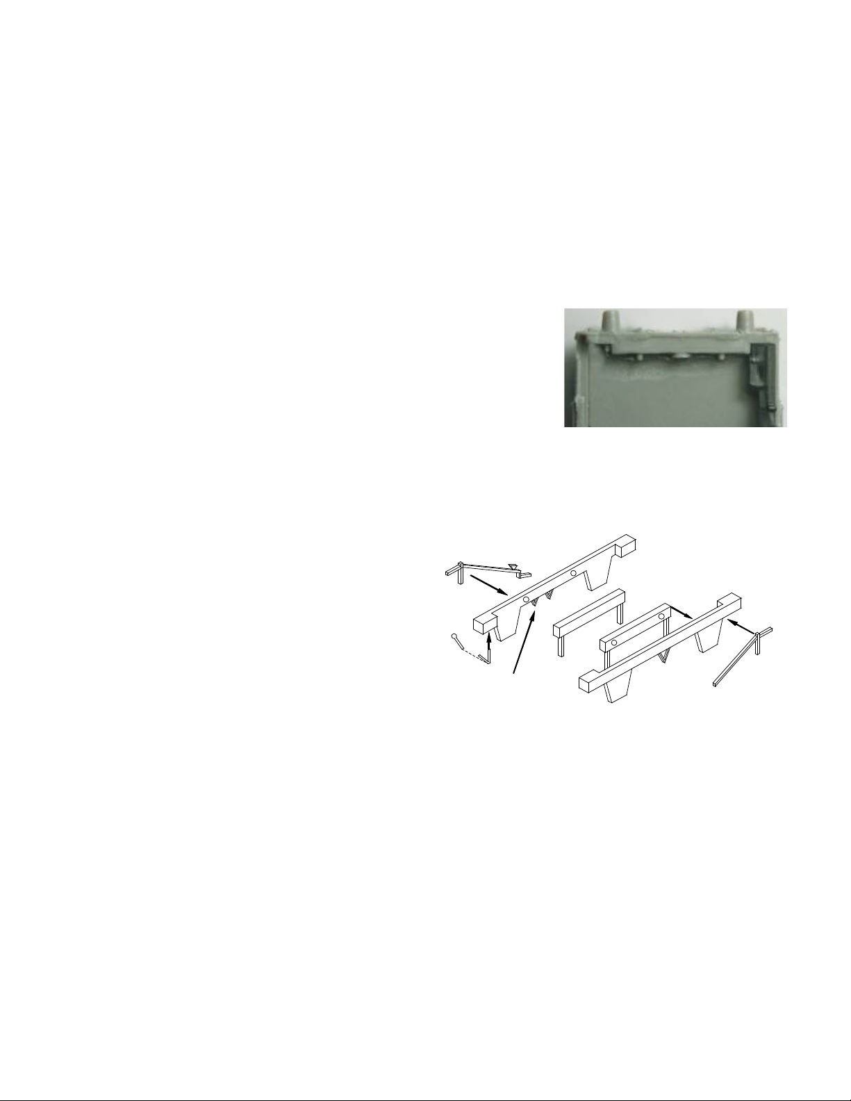
Brake Levers
11. Decide whether to use either the GWR (Churchward)
brake levers (Parts 6 and 7) or the standard RCH
type (Parts 13 and 14).
12. If using the GWR type, remove the small right-hand V-hanger from the chassis side with the two V-hangers (Part
9). Glue the brake lever (Part 7) onto the bracket (Part 6) then glue the brake lever/bracket assembly onto the
right-hand corner of each chassis side.
13. If using the RCH type, glue the left-hand brake lever (Part 13) to the left-hand chassis side (Part 9) and the right-
hand brake lever ((Part 14) to the right-hand chassis side (Part 10). Bend the brake levers inwards very slightly as
this will help them to make contact with the V-hangers.
Buffers
14. The brass buffer heads included in the Parkside chassis kit have a shank diameter of 0.7mm. By drilling out the
holes in the buffers on the ends slightly less than this (for example, 0.6mm) then the brass buffer heads can be an
interference fit to the ends by very carefully pushing them on. Do not force! If they are too tight a fit, then enlarge
the holes in the buffers. If the brass buffer heads are a loose fit, then secure them with a very small drop of
superglue.
Couplings
15. Place the coupler (Part 17) into the coupler pocket (Part 15) and insert the coupler pocket plug (Part 16) above it
so that the hollow face of the coupler pocket plug is facing upwards. The coupler pocket plug is usually an
9
10
11
12
13
14
Remove for
GWR type
6
7

N Gauge Society Kit 2 – GWR Mink C Box Van
Page 4 of 4
interference fit; if it is slightly loose, apply glue very sparingly in order to avoid gluing the coupler to the coupler
pocket.
16. Glue the assembled couplings under the floor of the wagon behind the headstock –
there are two protruding notches that will keep it aligned in the centre. Only use the
minimum amount of glue necessary so that the coupling still moves up and down.
Note that you may choose to leave the couplings off until the wagon has been
painted.
Weight
17. Plastic kits can be light, and some modellers find that a little weight improves running qualities. There is plenty of
room inside the van body to fit a little bit of lead weight before attaching the roof.
Roof
18. Clean up any mould marks on the roof (Part 4) with fine wet and dry emery paper prior to gluing in place The roofs
of these vehicles when new were painted white, but this of course rapidly changed to grey/black when the wagons
went into service. It is probably easier to paint the roof and the wagon body separately before gluing one to the
other.
Transfers (not included)
19. It is advisable to prepare the painted surface with a gloss finish as this will accept transfers more easily and the
carrier will not show as much. Use a gloss varnish or ‘Klear floor polish’.
20. Cut round the transfers using a sharp knife and a steel ruler – always cut with the ruler over the transfer to avoid
damaging it.
21. To apply the transfers, soak them in a dish of warm water for a few seconds, drain off the water, lay on a flat
surface and then use the tip of a cocktail stick to check that the transfers will move free of the backing paper – if
not, return to the water and repeat this step. Once the transfer moves, place it on the model and use the tip of the
cocktail stick to hold one end to the model while pulling the backing sheet away with tweezers. There should be
time to make a few adjustments as necessary.
22. Leave all the transfers to dry for half an hour and then apply a ‘decal setting solution’ (such as Micro-Sol) if
required which will help the transfers to lie and form over detail. Then leave overnight before applying a coat of
matt varnish to seal the transfers to the model.
Congratulations! Your model is now complete.
15
17
16
Table of contents
Other N Gauge Society Toy manuals

Popular Toy manuals by other brands

LEGO
LEGO harry potter 4840 Assembly guide

Fisher-Price
Fisher-Price LittleMommy instructions

Radio Shack
Radio Shack Magbug 60-547 quick start guide

MGA Entertainment
MGA Entertainment Project MC2 Crayon Makeup Kit quick start guide

Black Horse Model
Black Horse Model Spitfire MK Instruction manual book

Tomy
Tomy THOMAS & FRIENDS 4750 Assembly instructions


