manuals.online logo
Brands
  1. Home
  2. •
  3. Brands
  4. •
  5. Nabco
  6. •
  7. Lock
  8. •
  9. Nabco GT1175 U19 User manual

Nabco GT1175 U19 User manual

1 of 3
GT1175 Telescopic, U19 Electric Lock Kit
Instrucon Sheet
P/N C-00336 Rev 3-15-18
Nabco Entrances Inc. S82 W18717 Gemini Drive Muskego, Wisconsin 53150
Phone: (877) 622-2694 Fax: (888) 679-3319 www.nabcoentrances.com
NABCO hours of Operaon: Monday to Friday 8:00 a.m.- 4:30 p.m. (Central Time)
Nut, Wire, Range
22-14AWG, Grey
P/N T-00197
SERVICE PARTS: TELESCOPIC KIT
U19 FAIL SECURE: P/N A01228
U19 FAIL SAFE: P/N A01229
Harness, Handing
Microprocessor
P/N M-01190
Relay Asm, E.Lock; U19
Fail Secure P/N A-00780
Fail Safe P/N A-00781
DN 1964
Rivnut
1/4-20, .027-.165
P/N T-00048
Hex Head Screw
1/4-20x.750L
P/N T-00064
Electric Strike, Telescopic
Fail Secure: P/N A-00293
Fail Safe: P/N A-00294
Bracket, Elec.
Lock Repl.Kit
P/N A-01224
Washer, Lock, 1/4”
P/N T-00087 Parts Bag,
Elect. Lock U30 Telesc.
P/N A-01225, Fail Secure
P/N A-01226, Fail Safe
Aenon: Electric Locks can not prevent Breakout. If prevenng Breakout is deemed necessary, panic hardware
must be ed to the Door Panels.
CHAPTER 1: REPLACE THE BELT CLIP
1. Use the same hardware from the exisng Belt Clip to replace the exisng Belt Clip with the Electric Lock Belt Clip.
CHAPTER 2: INSTALL THE ELECTRIC LOCK
1. Fully Close the Lead Door. Go to the Latch located on the Electric Lock Belt Clip.
2. Align the Center of the Latch to the front face of the Box Beam. Mark that spot.
Elec. Lock Bracket
Lead Door
DN 1966
Carrier
Front Face
of Box Beam
Riv Nut
Lock Washer
Strike
Hex Head Screw
Marked Spot
Electric Lock
Figure 1 Install the Electric Strike and Electric Lock Belt Clip
2 of 3
GT1175 Telescopic, U19 Electric Lock Kit Instrucon Sheet www.NabcoEntrances.com
P/N C-00336 Rev 3-15-18
3. Mark and drill out (1) Retangle Hole and (4) Rivnut Holes onto the front face of the Box Beam according to the Template
located in CHAPTER 5.
4. Insert (1) 1/4-20 Rivnut into each Rivnut hole.
5. Insert the Electric Lock into the Cutout.
6. Ensure the Flat side of Latch faces the Strike on the Electric Lock.
7. Loosely secure the Electric Strike to the Box Beam with (4) 1/4-20 x 1” Screws and 1/4” Lock Washers.
8. Fully close the Slide door.
a. A slight gap must exist between the Latch and the Strike.
b. Ensure the Belt Clip does not hit the Speed Reducer Roller.
9. Fully Open the Slide Door. Ensure the Belt Clip does not hit the Drive Belt Roller.
10. Make adjustments if deemed necessary.
DN 1968
Slight Gap
Strike
Flat side of Latch
Speed Reducer Roller
Drive Belt Roller
Door Fully Closed Door Fully Open
Figure 2 Ensure Terminal Strip is Facing Strike Side of Slide Door
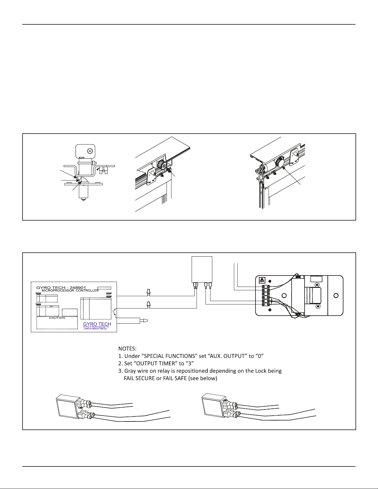
CHAPTER 3: GENERAL WIRING
Aenon: Electric Lock only works in One Way mode or Night Mode.
DN 1913
FAIL
SECURE
VIO
GRY
WHT
BLK
1
6
110V
Wire Nut
103125
BROWN 60"
VIOLET 60"
No.
HANDY TERMINAL (6P)
SENSOR (12P)
1.Please adjust this operator as per instruction manual.
2.Turn the power off, before opening the box.
3.Don't open this box except for replacing fuse.
Otherwise, the warranty will be terminated.
4.Repair of this unit except by Lanson Industries, Inc.
may cause software and hardware malfunction.
USE [SLIDER/SWINGER]
For continued protection
against fire, replace only
with same type and rating
of fuse.
WARNING
FUSE INSIDE
RATING:125V,4A
SIZE:5.2 x 20mm
COLOR
BROWN
RED
BLACK
WHITE
GREEN
ORANGE
ORANGE
ORANGE
YELLOW
BLUE
VIOLET
GRAY
7
61
6B
9DC12V
SYMBOL
H
M0
M1
62
BA
OUT +
OUT -
SQ
1
2
3
4
NO.
5
6
7
8
9
10
11
12
POWER SOURCE (4P)
OPERATOR (6P)
EMPTY
115VAC HOT
EMPTY
115VAC COMMONWHITE
BLACK
1
2
3
4
COLORNO.
MOTOR V PHASE
ENCODER 12VDC
ENCODER A PHASE
MOTOR U PHASE
ENCODER GND
ENCODER B PHASE
ORANGE
RED
BROWN
YELLOW
COLOR
BLUE
BLACK
1
2
3
4
5
6
NO.
OUT+
(VIOLET)
OUT-
(GRAY)
7 (RED)
9DC12V
(BROWN)
GREY 10"
VIOLET 10"
BROWN 60"
VIOLET 60"
GREY 10"
VIOLET 10" BROWN 60"
VIOLET 60"
GREY 10"
VIOLET 10"
FAIL SECURE RELAY WIRING FAIL SAFE RELAY WIRING
U-SERIES CONTROL
(U19 OR EARLIER)
RELAY
LOCK
TO 120VAC
3 of 3
www.NabcoEntrances.com Gt1175Telescopic,U19ElectricLockKitInstruconShee15
Rev 3-15-18 P/N C-00336
CHAPTER 4: CHANGE HANDING OF SLIDE DOOR
Note: Handing of the Slide Door is only necessary if the Slide Door: Opens when it should Close; or Closes when it should Open.
1. Obtain the Handing Harness provided within the Parts Bag.
2. Go to the Motor Harness that is connected to the Motor and the U-19 Microprocessor Control.
3. Separate the Motor Harness to connect the Handing Harness between the connectors.
Motor Connector (6 pin)
Power Connector (4 pin)
Size: 5.2 x 20mm
Rang: 125V, 5A
Fuse Inside
No.
COLORSYMBOLNO.
12
11
10
9
8
7
6
5
4
3
2
1
OUT -
OUT +
BA
SQ
62
M1
M0
H
6 B
61
7
9DC12V
Gray
Violet
Blue
Yellow
Orange
Orange
Orange
Green
White
Black
Red
Brown
COLORNO.
6
5
4
3
2
1
Yellow
Black
Blue
Brown
Orange
Red
USE
Encoder B Phase
Encoder Ground
Motor U Phase
Encoder A Phase
Encoder 12 VDC
Motor V Phase
USECOLORNO.
4
3
2
1
Black
White
Not Used
115 VAC Hot
115 VAC Common
Not Used
WARNING
type and rang.
with a fuse of the same
against fire, replace only
For connued protecon
CAUTION
DN 0749
Handing Harness
Motor Harness & Plug
Microprocessor Control
Motor
Figure 3 Change Handing of Slide Door
CHAPTER 5: ELECTRIC STRIKE TEMPLATE
DN 1975
RECTANGULAR
CUTOUT
!!!VERIFY DIMENSIONS
BEFORE USING TEMPLATE!!!
SCALE PATTERN
1-7/8”
2-7/8”
1/2”
2-5/8”
3-7/8”
3/8”
25/64”
Rivnut Hole
25/64” Corner Hole
for Retangle Cutout
1. Center the template to the marked spot, and tape to the front face of Box Beam. Center Punch on each Center Mark.
2. Go to the Rectangular Cutout. Drill (1) 25/64” diameter hole through each Center mark all the way through both walls of the
Box Beam.
3. Go to the outside holes of the Retangular Cutout. Drill (1) 25/64” hole through each Center mark through (1) wall only. DO
NOT drill through both walls.

This manual suits for next models

2

Other Nabco Lock manuals

Nabco GT1175 U-19 User manual

Nabco

Nabco GT1175 U-19 User manual

Nabco GT1175 U-19 Specification sheet

Nabco

Nabco GT1175 U-19 Specification sheet

Popular Lock manuals by other brands

COMPX 1T-058 Information

COMPX

COMPX 1T-058 Information

Iseo Zero1 installation guide

Iseo

Iseo Zero1 installation guide

UNISEM UniTracer L-100 user manual

UNISEM

UNISEM UniTracer L-100 user manual

Dorma ARCOS Office Mounting instructions

Dorma

Dorma ARCOS Office Mounting instructions

Stock Loks CA-12L instruction sheet

Stock Loks

Stock Loks CA-12L instruction sheet

Yakima SKS Series Installation

Yakima

Yakima SKS Series Installation

COLFERT MANIGLIE KATA VELA Assembling instructions

COLFERT

COLFERT MANIGLIE KATA VELA Assembling instructions

Assa Abloy OneSystem 509N Safety instructions

Assa Abloy

Assa Abloy OneSystem 509N Safety instructions

Lockwood ASSA ABLOY Induro installation instructions

Lockwood

Lockwood ASSA ABLOY Induro installation instructions

Alarm Lock CYLINDER ADAPTER KIT Addendum Using

Alarm Lock

Alarm Lock CYLINDER ADAPTER KIT Addendum Using

Weiser Kevo user guide

Weiser

Weiser Kevo user guide

Dormakaba SafeRoute-System Mini user manual

Dormakaba

Dormakaba SafeRoute-System Mini user manual

Smartlock Digital Axessor USB operating manual

Smartlock Digital

Smartlock Digital Axessor USB operating manual

Flipo My Safe Block quick start guide

Flipo

Flipo My Safe Block quick start guide

COMPX C8188 Dimensional drawing

COMPX

COMPX C8188 Dimensional drawing

Assa Abloy effeff EX118R installation instructions

Assa Abloy

Assa Abloy effeff EX118R installation instructions

D&D Technologies MagnaLatch MLSPS2 installation instructions

D&D Technologies

D&D Technologies MagnaLatch MLSPS2 installation instructions

Kaba C-lever compact quick guide

Kaba

Kaba C-lever compact quick guide

manuals.online logo
manuals.online logoBrands
  • About & Mission
  • Contact us
  • Privacy Policy
  • Terms and Conditions

Copyright 2025 Manuals.Online. All Rights Reserved.