North American Clutch & Driveline
Rockford, Illinois
Phone: (800) 383-9204
(815) 282-7960
Fax (815) 282-9160
www.naclutch.com
5
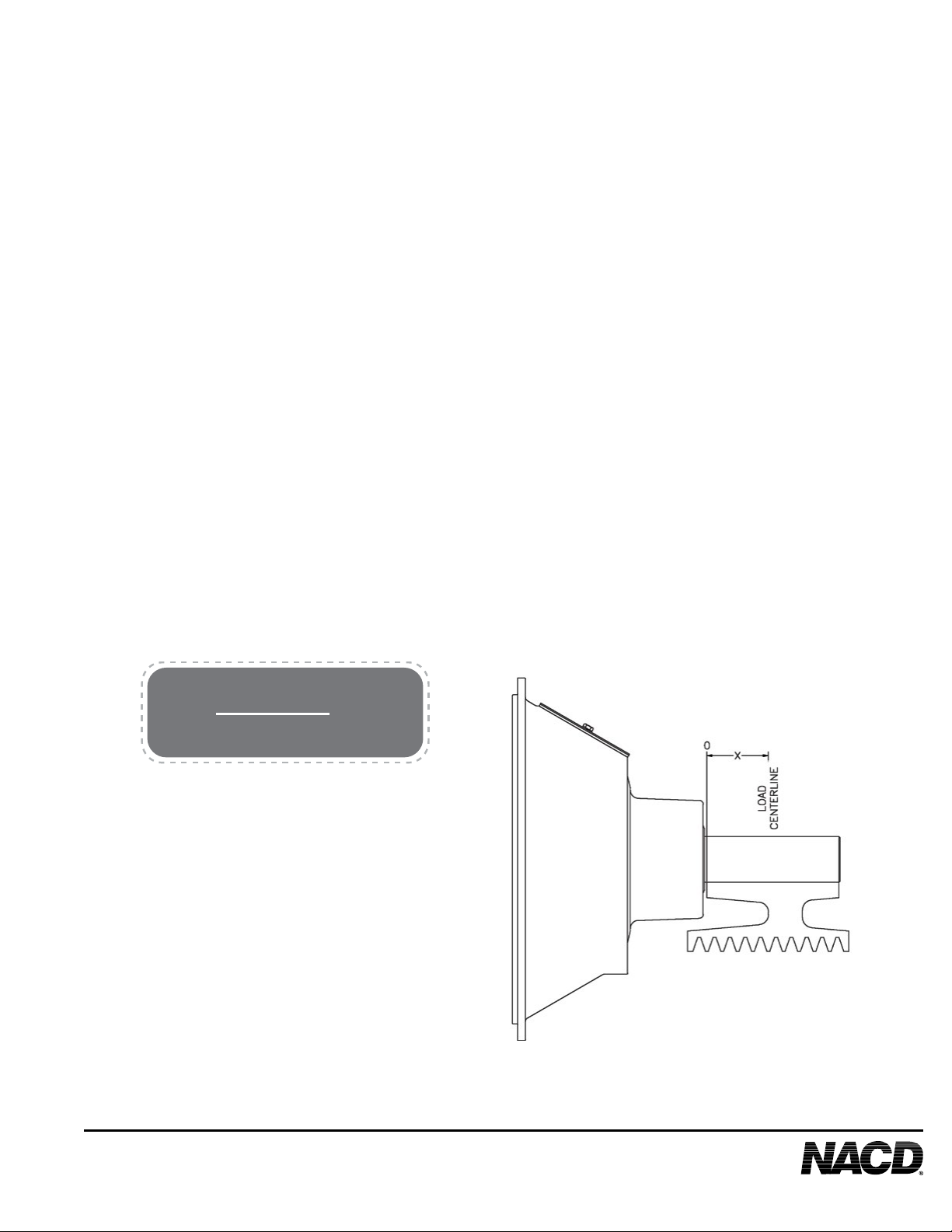
2.5 Maximum Safe Operating Speeds
Maximum safe operating speed is 2200 rpm for NACD Power Take-Offs with 14” HD,
14” HD (DP) or 14” HD (TP) clutches used for either in-line or side load drives.
2.6 Required Clutch Torque Capacity
To determine the actual torque capacity required of a clutch used for any given
application the maximum engine torque and torque service factor must be considered.
See the following chart and formula to calculate the proper clutch capacity required for
the application.
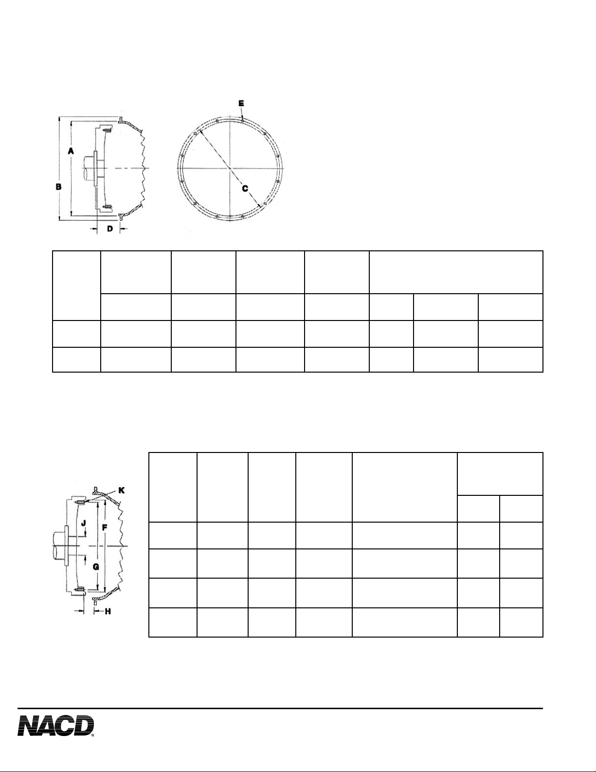
2.7 Alignment Tolerances For Flywheels & Flywheel Housings
NOTE: NACD recommends that engine ywheel housings used with NACD PTO’s be
made of quality cast iron or other material of equal or better strength. Aluminum ywheel
housings have been found to provide insufcient strength to properly maintain bearing
alignment and support the weight and forces related to the application.
Check the alignment of the engine ywheel and the engine ywheel housing. Excessive
bore and face runout of the ywheel, ywheel housing, and ywheel housing adapters,
if used, can adversely affect the performance of the PTO and the system of which it is
part. A dial indicator will be required to measure alignment.
Required Clutch Torque Capacity Calculation:
Required Clutch Torque = Maximum Engine Torque x Service Factor
Blower or Vacuum
Centrifugal with free ow of air
With high start-up inertia or subject
to choking of air supply
Compressors
Reciprocating, 1 or 2 cylinders
Reciprocating, 3 or more cylinders
Roto screw or turbine
Conveyor
Fed uniformly
Not fed uniformly
Recriprocating
Drills
Generator
Pump
Centrifugal or Turbine
Dredge
Mud or reciprocating
Rock Crusher, Hammer Mill
Snow Blower
Wood Chipper, Saw Mill
Ratings: Shafts, bearings and clutch capacities are rated on a conservative
basis. For unusually heavy starting loads, frequent engagment service,
or if prime mover is engine of less than 4 cylinders, consult our sates
representatives for recomendations. Extremely low speed engines require
special consideration.
1.7
4.0
4.0
2.5
2.0
1.5
2.0
3.0
2.0
2.0
1.5
2.0
3.0
3.0
2.0
3.0