Nakanishi Sheenus neo User manual

超音波研磨装置/UltraSonic Polisher
取扱説明書 /OPERATION MANUAL
OM-K0517 001
目 次
1.
CAUTIONS FOR HANDLING AND OPERATION
・・・ P16
2.
SPECIFICATIONS AND DIMENSIONS
・・・・ P18
3. COMPONANT NAMES ・・・・・・・・・・・・・・・ P18
4. PREPARATION BEFORE USE ・・・・・・・・ P22
5. ATTACHMENT OF THE TOOL ・・・・・・・・ P23
6. OPERATING PROCEDURES ・・・・・・・・・ P24
7. PROTECTION CIRCUIT ・・・・・・・・・・・・・・ P24
8.
FINISHING OPERATION BY ULTRASONIC POLISHER
・・・ P25
9. CHANGING FUSES ・・・・・・・・・・・・・・・・・・ P26
10.
HOW TO SET THE CONTROL UNIT
・・・・ P27
11. SYMBOLS・・・・・・・・・・・・・・・・・・・・・・・・・・・ P27
12.
SIMPLE TEST METHOD USING THE TEST HORN
・・ P28
13. TROUBLESHOOTING・・・・・・・・・・・・・・・・ P29
1. 安全上の注意・表示について ・・・・・・・・・・・ P 2
2. 仕 様 ・・・・・・・・・・・・・・・・・・・・・・・・・・・・・・・ P 3
3. 各部の名称 ・・・・・・・・・・・・・・・・・・・・・・・・・・・ P 4
4. 使用前の準備 ・・・・・・・・・・・・・・・・・・・・・・・・・ P 6
5. 工具の交換方法 ・・・・・・・・・・・・・・・・・・・・・・・ P 7
6. 操作方法 ・・・・・・・・・・・・・・・・・・・・・・・・・・・・・ P 8
7. 保護回路について ・・・・・・・・・・・・・・・・・・・・・ P 9
8 . 超音波仕上げ作業の要点 ・・・・・・・・・・・・・・・ P 9
9 . ヒューズの交換方法 ・・・・・・・・・・・・・・・・・・・ P10
10. 操作パネルの設定方法 ・・・・・・・・・・・・・・・・・ P11
11. シンボル ・・・・・・・・・・・・・・・・・・・・・・・・・・・・・ P11
12.
テストホーンを使用した簡易的な振動確認方法
・・ P12
13. 故障の原因と対策 ・・・・・・・・・・・・・・・・・・・・・ P13
CONTENTS

16
Thank you for purchasing the Ultrasonic Polisher SHEENUS neo. This product is designed for grinding,
polishing, and mirror finishing on a wide range of materials from aluminum dies to cemented carbide dies. And
has a wide variety of finishing tools such as diamond stone, diamond file, ceramic stone and wooden lapping
tools. Read this Operation Manual carefully before use.
1. CAUTIONS FOR HANDLING AND OPERATION
■Please read the operation manual thoroughly, make sure you understand all warnings and cautions prior to
operating the system and only use the system in the manner intended.
■
These warnings and cautions are intended to avoid potential hazards that could result in personal injury or
damage to the device. These are classified as follows in accordance with the seriousness of the risk.
Class Degree of Risk
WARNING A hazard that could result in bodily injury or damage to the device if
the safety instructions are not properly followed.
CAUTION A hazard that could result in light or moderate bodily injury or damage
to the device if the safety instructions are not followed.
INFORMATION
Be sure to keep the usage for your safety.
A. GROUNDING INSTRUCTIONS
①In the event of a malfunction or breakdown, grounding provides a path of least resistance for
electric current to reduce the risk of electric shock. This tool is equipped with a power cord
having an equipment grounding conductor and a grounding plug. The plug must be plugged into
a matching outlet that is properly installed and grounded in accordance with all local codes and
ordinances.
②Do not modify the plug provided-if it will not fit the outlet, have the proper outlet installed by a
qualified electrician.
③Improper connection of the equipment-grounding conductor can result in a risk of electric shock.
The conductor with insulation having an outer surface that is green with or without yellow stripes
is the equipment grounding conductor. If repair or replacement of the power cord or plug is
necessary, do not connect the equipment-grounding conductor to a live terminal.
④Check with a qualified electrician or service personnel if the grounding instructions are not
completely understood, or if in doubt as to whether the tool is properly grounded.
⑤Use only 3-wire extension cords that have 3-prong grounding plugs and 3-pole receptacles that
accept the tool's plug.
⑥(120V) This tool is intended for use on a circuit that has an outlet that looks like the one illustrated
in Sketch A in Figure (below). The tool has a grounding plug that looks like the plug illustrated
in Sketch A in Figure (below). A temporary adapter, which looks like the adapter illustrated in
Sketches B and C, may be used to connect this plug to a 2-pole receptacle as shown in Sketch B
if a properly grounded outlet is not available. The temporary adapter should be used only until a
properly grounded outlet can be installed by a qualified electrician. The green-colored rigid ear,
lug, and the like, extending from the adapter must be connected to a permanent ground such as a
properly grounded outlet box.
NOTE: Adapter in (Figure B) is not for use in Canada.
⑦Return to NAKANISHI dealer service for servicing / repair.

GROUNDING
PIN GROUNDING
PIN
METAL
SCREW
(A)
COVER OF GROUND
OUTLET BOX
(B)
(C)
(D)
ADAPTER
GROUNDING
MEANS
⑧Use proper extension cord. Make sure your extension cord is in good condition. When using an
extension cord, be sure to use one heavy enough to carry the current your product will draw. An
undersized cord will cause a drop in line voltage resulting in loss of power and overheating. Table
(below) indicates the correct size to use depending on cord length and nameplate ampere rating. If
in doubt, use the next heavier gauge. The smaller the gauge number, the heavier the cord.
Ampere Rating
Volts Total length of cord
120V
240V
7.5m (25ft.)
15m (50ft.)
15m (50ft.)
30m (100ft.)
30m (100ft.)
60m (200ft.)
45m (150ft.)
90m (300ft.)
More Than Not More Than
0 6 18 16 16 14
6 10 18161412
10 12 16 16 14 12
12 16 14 12 Not Recommended
Only the applicable parts of the Table need to be included. For instance, a 120-volt product need include the
240-volt heading.
B. WARNING
①Always wear safety glasses. Everyday eyeglasses only have impact resistant lenses, they are not
safety glasses. Also use a dust or face mask whenever the system is operating.
②Make sure to connect the earth cables to ground before use.
③Do not use near flammable substances or in explosive atmospheres. Contact with flammable
substances while the system is operating may cause a fire.
④Do not use in dangerous environments. Protect the Control Unit from moisture, dust, corrosive
gasses, near chloride vapors, and out of direct sunlight. All of which can cause pre-mature failure.
Failure to protect the Control Unit can result in damage to internal components and result in injury
to the operator.
⑤Ultrasonic vibration may cause noise during use. Earplugs or ear protection is recommended.
⑥Never place the air vents upward or block the air vents in the rear/bottom of the Control Unit when
in use.
⑦Contamination or scratches on the tool thread, the Handpiece or the ultrasonic horn may cause
abnormal vibration or overheat.
⑧Attach the tool firmly to the ultrasonic horn. If the tool is not attached firmly, the power would go
down or the hanpiece would overheat.
⑨The tool or the tip holder may heat up due to ultrasonic vibration even though under normal
conditions. Holding them tightly or pressing against the skin may cause a burn.
⑩Do not hit, disassemble, modify or attempt to repair the control unit and or Handpiece. Additional
damage will occur to the internal components. If the control unit is disassembled, electric shock
may occur from high voltage areas on internal circuit boards. If the Control Unit is tampered
with, warranties may be voided. Service must be performed by NSK NAKANISHI or an authorized
service center.
⑪Protect the Handpiece from oils and liquids. This may cause premature hand-piece failure. Do not
spray cutting oil or lubricants on the Handpiece.
⑫Do not touch the tool, tip holder or ultrasonic horn while the system is operating. The components
and tools may be very hot and cause injury.
17

18
2. SPECIFICATIONS AND DIMENSIONS
2 - 1 Control Unit
Model NE240
Oscillation frequency 22.5KHz
Frequency Control Homing Type
Output
45W max. (UNCLAMP MODE)
20W max. (CLAMP MODE)
Power Conditioning Continuous variable type
Power Source AC120V, 50 / 60Hz
AC230V, 50 / 60Hz
Rating Input 55VA
Appropriate fuse AC120V : T1.6AH 250V
AC230V : T1AH 250V
Dimensions W225 ×D195 ×H97mm
Weight 2.1 kg
C. CAUTION
①Use at room temperature (10 degrees C to 40 degrees C) with no appreciable humidity. Failure to
follow this may cause a short circuit or electric shock.
②Check the operating conditions before use. If any abnormality is found, return to the dealer where
you purchased the Sheenus neo for repair.
③When installing the control unit, provide space of approximately 10cm around the control unit for
easy access to the plug of power cord in case of emergency.
④If tools, tip holder or the Handpiece get hot and/or the pitch of the noise changes suddenly during
use, stop immediately and check all components. If the tool is broken, do not continue to use the
tool. Replace with a new tool immediately.
⑤The system functions normally in the environment where the temperature is at 10 - 40ºC (75 -
104ºF), humidity at 30 - 75% RH, and with no moisture or condensation near the Control Unit.
Usage outside of this recommended range may cause a malfunction.
⑥Store the system in the place where the temperature is at -10 - 50ºC (14 - 140ºF), humidity at 10 -
85%RH, atmospheric pressure at 500 - 1060hPa, Store the unit where it will not be subject to air
with dust, sulfur, or salinity.
D. INFORMATION
①Be sure to only use with Power Supply Cord of the standard accessories.
Using a non-specified Power Supply Cord, the risk of fire by over-heating of the cord is possible.
If damage to the Power Supply Cord, return to NAKANISHI dealer service for servicing / repair.
②This product utilizes an ultrasonic transmitter. It may affect computers and LAN cables nearby.
Also radio receivers may pick up noise.
③Turn OFF the Main Power Switch after use. If you do not use for a long time, unplug of the power
cord.
④Users are responsible for safe operation and maintenance.

19
2 - 2 Handpiece
Model US-25PB
Oscillator PZT piezoelectric type
Cord length 2m
Weight 140g (excluding cord)
Standard Accessories
・Power Cord (2m)・・1pc.
・Wrench (10mm)・・2pc.
・Fuses
For AC120V…T1.6AH 250V …2pcs.
For AC230V…T1AH 250V …2pcs.
・Foot Switch (FC-24)・・1pc.
・Allen Wrench (2.5mm)・・1pc.
・Too l C a s e ・・1pc.
・Handpiece Stand・・1pc.
Standard Tools
・Tip holder (Round for ȭ3.0mm)・・1pc.
・Tip holder (Flat for t = 1.0mm)・・1pc.
・Ceramic fiber grindstone #800 (Flat 6 ×50mm t = 1)・・1pc.
・Electroplated diamond file #200 (Flat taper 4 ×50mm t = 0.4) ・・1pc.
3 - 1 Standard Set
Fig. 1
2 - 3 Standard Accessories
3. COMPONANT NAMES
①Control Unit (NE240)
②Handpiece (US-25PB)
③Foot Switch (FC-24)
①
Control Unit
(NE240)
②
Handpiece
(US-25PB)
③Foot Switch
(FC-24)

20
④Main Power Switch
ON / OFF Main Power Source. The designation " I " indicates ON. The designation " O " indicates OFF.
⑤UNCLAMP ( ) / CLAMP ( ) Switch
This switch will change the UNCLAMP mode ( ) or CLAMP mode ( ).
・UNCLAMP mode ( )
When using a One-Piece tool, set to the UNCLAMP mode ( ).
・CLAMP mode ( )
When using the tip holder (manually mounted tips) and M4 Screw Joint Adapter, set the unit to the CLAMP
mode
(). When using the tip holder (files) or the M4 Screw Joint Adapter (the M4 one-piece tools
mounted) and setting to the unit to UNCLAMP mode (
), excessive vibration and heat will damage the
Handpiece ②and or Control Unit ①.
⑥ON / OFF Switch
This is to turn Control Unit power or OFF. The ON LED lamp (GREEN) is on at start up and during normal
operation the OFF LED lamp (GREEN) is when shutdown. When the CLAMP protection circuit stops the Control
Unit ①, the RESET LED lamp (RED) lights up and the Control Unit ①will need to be restarted by pressing the
RESET Switch twice after correcting the problem.
⑦DISPLAY Switch
By pressing the DISPLAY Switch ⑦, the LED display can be changed from Watt / Power.
⑧DISPLAY
The selected Watt / Power value is shown on the display.
WATT:Electric power supplied to the oscillator is shown.
The heat generated in the Handpiece ②, tip holder and tool is proportional to the power applied
to the oscillator, too much power will cause the Handpiece ②, tip holder and tool to overheat and
possibly burn. If the Handpiece ②, tip holder or tool becomes hot, lower the power setting. Use
great care to avoid touching the tip holder and tool during working as they can cause severe burns.
POWER:Output level is shown.
Applicable display range is 0 - 49. (with the test tool, UNCLAMP mode
( ) is 19 - 49, CLAMP
mode ( ) is 8 - 23.)
⑨Power Control Knob
Turn the Power Control Knob ⑨to control the output.
⑩Receptacle for Connecting Handpiece
Connect the plug of Handpiece Cord.
3 - 2 Front of Control Unit (NE240)
Fig.2
⑧Display
⑦DISPLAY Switch
⑨Power Control Knob
⑩Receptacle for
Connecting Handpiece
⑤UNCLAMP / CLAMP Switch
⑥ON / OFF Switch
④Main Power Switch

21
3 - 3 Rear of Control Unit
Fig. 3
⑪Socket for Foot Switch
Connect the Plug of Foot Switch ③.
⑫Inlet with Power Supply Fuses
Insert the Power Cord here.
Two Fuses are possible (for AC120V : T1.6AH, for AC230V…T1AH 250V). Verify and use only the properly
rated and type fuses.
⑫
Inlet with Power
Supply Fuses
⑪Socket for
Foot Switch
Fig. 4
3 - 4 Handpiece (US-25PB)
⑬Protector Sleeve
The Protector Sleeve
⑬
is to protect hands from touching the heated tool joint. If using the Handpiece
②
without
attaching the Protector Sleeve
⑬
, burn injuries can occur. Always attach the Protector Sleeve to the Handpiece
②
.
⑭Test Horn
When you unpack the carton, the Test Horn ⑭is attached to the front end of Handpiece ②.
The Test Horn ⑭is used to verify that the Handpiece ②is correcting generating the ultrasonic oscillation for
normal operation.
When using the Handpiece ②, remove the Test Horn ⑭from the Handpiece ②.
⑮Tip Holder
Holder to attach special tip tools.
⑯One-Piece Tool
M-6 one-piece tools can be used directly attached to the Handpiece ②. When using M4 one-piece tools, attach
the tool to the M4 Screw Joint Adapter and then attach to the Handpiece ②.
⑰M4 Screw Joint Adapter
M4 Screw Joint Adapter is used to attach an M4 one-piece tool to the Handpiece ②.
⑮Tip Holder
⑬Protector Sleeve
⑯One Piece Tool
⑰M4 Screw
Joint adapter
⑭Test Horn

22
4. PREPARATION BEFORE USE
(1) The Test Horn ⑭comes with the Handpiece ②. Remove the Protector Sleeve ⑬and unscrew the Test
Horn ⑭using the two wrenches provided.
Fig. 5
(2) Insert the output plug of the Hand-piece into
the Receptacle for Connecting Handpiece ⑩to
the Control Unit ①.
Fig. 6
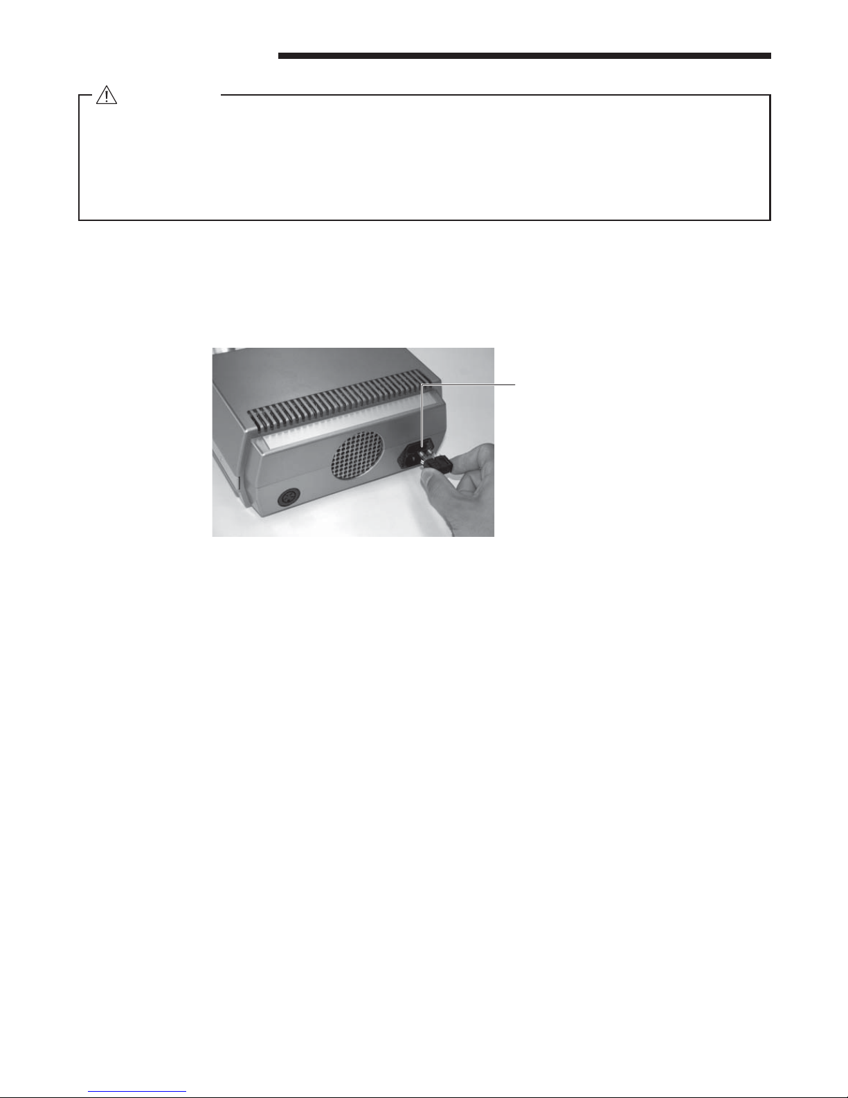
(3)
Make sure that the Main Power Switch ④is OFF
,
and connect the power cord to the Inlet with
Power Supply Fuses ⑫of the Control Unit ①.
Fig. 7
(4)
When using the Foot Switch
③
, connect the Plug
of the Foot Switch to the Socket for Foot Switch
⑪.
Fig. 8
④Main Power Switch
⑩
Receptacle for
Connecting
Handpiece
Output Plug of the
Handpiece
⑫Inlet with Power
Supply Fuses
Main Power Cord
⑪Socket for
Foot Switch
Plug of the
Foot Switch
⑬Protecter
Sleeve
⑭Test Horn

23
5. ATTACHMENT OF THE TOOL
5 - 1 Attachment of One-Piece Tools ⑯, Tip Holders ⑮and M4 Screw Joint Adapter ⑰
Attach the Tip Holders ⑮or the M4 Screw Joint Adapter ⑰
to the Handpiece ②and clamp tightly using two provided
wrenches. (Fig. 9).
Then reattach the Protector Sleeve ⑬.
Fig. 9
5 - 2 Attachment of Tip tools (e.g. ceramic grind stone tip)
Insert the grind stone tip to the Tip Holder ⑮and tighten
the screw using the provided Allen Wrench (2.5mm). If the
clearance between the groove of the Tip Holders
⑮
and the
tool is too large, do not use excess force to tighten. Use a
thin metal shim. Reattach the Protector Sleeve ⑬.
Fig. 10
5 - 3 M4 Screw Joint Adapter
Attach the M4 Screw Joint Adaptor ⑰to the Handpiece ②
and clamp tightly using the two provided wrenches. Then
attach the M4 One-piece tool and clamp using the provided
wrenches, then reattach the Protector Sleeve ⑬.
Caution on attaching the tool
If the tool or the Tip Holder
⑮
is loose, oscillation will be weak and cause noise or overheating.
Tighten
Tighten
Allen Wrench (2.5mm)
Set Screw
Tool

24
6. OPERATING PROCEDURES
(1) Turn ON the Main Power Switch ④and make sure the Display ⑧appears.
(2)
Select UNCLAMP / CLAMP mode using the UNCLAMP / CLAMP Switch ⑤.
The UNCLAMP mode ( ) or CLAMP mode ( ) LED will illuminate green.
CAUTION
・Use CLAMP mode ( ) for the Tip Holders ⑮.
・Use CLAMP mode ( ) for the M4 Screw Joint Adaptor ⑰.
・Use UNCLAMP mode ( ) for One-Piece Tools ⑯(for M6).
・The screw size of the One-Piece Tools ⑯is M6 x 0.9. Do not use different sized screws.
・Never remove or attach the plug of Handpiece ②or the plug of Foot Switch while depressing
the Foot Switch ③. Failure to follow this warning may result in an error code or damage to the
Control Unit ①.
・Please use a maximum of 8W of electric power when in continuous operation.
・
Do not use Tip Holders ⑮with the Control Unit
①
set in UNCLAMP mode
(). Use CLAMP
mode (
) for clamped tools.
・
Using tools at too high a power setting can cause the tools and Tip Holders ⑮to get extremely
hot and damage the Handpiece
②
and Control Unit
①
, causing tools to burn and cause injuries.
(3) Set the Power Control Knob ⑨to a minimum setting.
(4)
Press the ON / OFF Switch ⑥. ON LED lamp will light up GREEN.
* When operating by the Foot Switch ③, the ON LED lamp will light up by pressing the Foot Switch ③.
(5) The display screen "WATT" "POWER" can be changed by pressing the DISPLAY Switch ⑦.
(6) Adjust output power to the optimum level for the work by turning the Power Control Knob ⑨clockwise.
(7) Press the ON / OFF Switch ⑥again to stop. The OFF LED lamp will light up green and stop the operation.
* When operating by the Foot Switch ③, releasing the Foot Switch ③will stop the operation.
(8) Make sure to turn OFF the Main Power Switch ④after use.
Fig. 11
7. PROTECTION CIRCUIT
⑧DISPLAY
⑦DISPLAY Switch
⑨Power Control Knob
⑤UNCLAMP / CLAMP Switch
⑥ON / OFF Switch
④Main Power Switch
(1) Protection System
The RESET LED lamp (RED) will illuminate and the operation will stop automatically in the following
situations.
・Too much pressure on the tool.
・The tool is not clamped properly.
・The tool is likely broke or the brazing on the tool is loose.
・The internal temperature in the Control Unit ①is too high.

25
(2)
How to release the protection circuit
Resolve the problem that caused the protection circuit to activate. Release the protection circuit by taking the
following actions.
・When operating by the ON/OFF Switch ⑥.
Toggle the ON/OFF Switch ⑥. The RESET LED (RED) will be turned OFF and the protection circuit will be
released.
・When operating by the Foot Switch ③.
Release the Foot Switch ③. The RESET LED lamp (RED) will be turned OFF and the protection circuit will
be released.
* When "01" is set for the Foot Switch ③change (refer to "11. HOW TO SET THE CONTROL UNIT" section),
press the Foot Switch ③or toggle the ON/OFF Switch ⑥. The RESET LED (RED) will be turned OFF and
the protection circuit will be released.
8. FINISHING OPERATION BY ULTRASONIC POLISHER
(1) Basic usage
The best method for using ultrasonic polishers is to press with slight pressure and keep the tools moving
over the surface of the work material. The figures below show the direction of the ultrasonic vibration and
the most effective direction to move the tool over the work surface. Ultrasonic vibration greatly reduces the
pressure required for fast material removal. Do not press the tool too hard and make sure the tool fits the
surface configuration properly. If required, you can grind the tool surface to the proper shape using diamond
tools or sand paper.
Fig. 12
Using flat surface
Secure contact between the
tool and the work surface.
Vibration direction / Slide direction
Using with angle
30 degree is the optimum
angle.
Using end face
Bottom cavity polishing can be
achieved using tip of the tool as
illustrated.
(2) SHEENUS neo tool length specifications
Please refer to the following table as a guideline to find the proper tool length. The length listed in the chart
is the length of the tool prior to mounting into the Tip Holders ⑮. Check to make sure that the tool is properly
clamped in the holder and that the holder is tightly fastened to the ultrasonic horn prior to operating the
system.
Special tools for SHEENUS neo Dimensions (mm) Appropriate length (mm)
Ceramic Fiber Grindstone
4 ×0.8 6 ×0.8
50 - 10
4 ×1.0 6 ×1.0
ȭ350-10
(3) Wood or brass lapping tips usage
When using wood or brass lapping tips select CLAMP mode ( ) and start at a very low power setting. If
too much power is applied the protection circuit will activate and stop the Control Unit ①.
26
9. CHANGING FUSES
WARNING
・Make sure to turn OFF the Main power switch ④and remove the power cord from the Inlet with
power supply fuses ⑫before replacing the fuse.
・Use intended fuse only.
Recommended fuses : AC120V : T1.6AH 250V
AC230V : T1AH 250V
(1) The Inlet with power supply fuses ⑫contains a fuse box inside. Push the clips on both side of the cap in and
pull the cap out.
(2) Use the intended fuse only. Replace both of the fuses when replacing the fuses.
(3) Push the clips of the cap into the inlet firmly.
Fig. 13
⑫Inlet with Power
Supply Fuses

27
10. HOW TO SET THE CONTROL UNIT
(1) Changing Watt display (0W display ⇒0.0W display)
・Turn OFF the Main Power Switch ④.
・Turn ON the Main Power Switch ④while pressing the UNCLAMP / CLAMP Switch ⑤.
・The DISPLAY ⑧shows WATT and 0.0 appears on the screen.
・Turn OFF the Main Power Switch ④and the setting is stored and completed.
・If you would prefer integral number, follow the same procedure again. The initial setting is 0.
(2) Alter the Foot Switch ③operation
The Foot Switch ③operation can be changed by Pressing-ON, Release-OFF operation to Press-ON, Press -
OFF again.
・Turn OFF the Main Power Switch ④.
・Turn ON the Main Power Switch ④while pressing the ON/ OFF Switch ⑥.
・The DISPLAY ⑧shows 00 (or 01). Press the ON /OFF Switch ⑥again and select 01 (or 00).
00 display: Press the Foot Switch ③to start, release the Foot Switch ③to stop.
01 display: Press the Foot Switch ③to start, press the Foot Switch ③again to stop.
・Turn OFF the Main Power Switch ④and the setting is completed. The initial setting is 00.
(3) Changing the non-use auto shutdown time
The Control Unit ①is equipped with a non-use auto shutdown timer that will shutdown the Control Unit ①
after extended periods of non-use. The default time is factory set to 3 minutes.
・Turn OFF the Main Power Switch ④.
・Turn ON the Main Power Switch ④with pressing the DISPLAY Switch ⑦.
・The DISPLAY ⑧shows 03. Press the DISPLAY Switch ⑦and select the time.
00 : Not available 01 : Turn OFF in 1 minute
02 : Turn OFF in 2 minutes 03 : Turn OFF in 3 minutes
05 : Turn OFF in 5 minutes 10 : Turn OFF in 10 minutes
・Turn OFF the Main Power Switch ④and the setting is complete.
Fig. 14
⑧DISPLAY
⑦DISPLAY Switch
⑨Power Control Knob
⑤UNCLAMP / CLAMP Switch
⑥ON / OFF Switch
④Main Power Switch
11. SYMBOLS
This product has been tested to the requirements of CAN/CSA-C22.2 No. 61010-1, second edition,
including Amendment 1, or a later version of the same standard incorporating the same level of testing
requirements.
This conforms to CE European Directive of "Machinery Directive 2006 / 42 / EC."
Hot surface. Do not touch.
This mark is a warning, caution and, or information. These are intended to avoid potential hazards that could
result in personal injury or damage to the product.
28
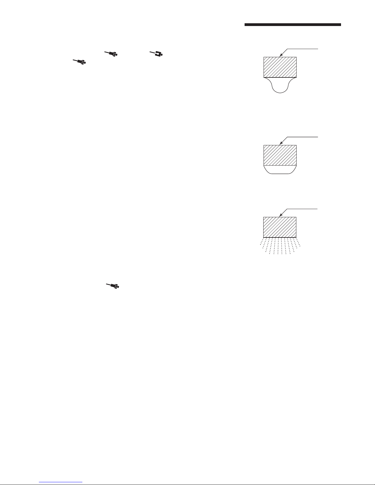
(1) Mount the Test Horn ⑭securely on the Handpiece ②.
(2)
Set the UNCLAMP ( ) / CLAMP ( ) Switch ⑤to UNCLAMP
mode ( ), and the Power Control Knob ⑨to MIN.
(3) Put a drop of water on the Test Horn ⑭(Fig. 15).
(4)
Turn ON the output ON / OFF Switch ⑥, keeping the Power Control
Knob ⑨at MIN.
Ultra sonic oscillation draws the water drop flat as shown on the
Test Horn ⑭(Fig. 16).
(5)
As you gradually increase the Power Control Knob ⑨to MAX, the
water drop on the Test Horn ⑭become vapor as shown Fig. 17.
In case oscillation is not output, or sufficient mist cannot be generated
in the UNCLAMP mode ( ), check if the Test Horn ⑭is not tightly
mounted on the Handpiece ②. Retighten it and repeat above test.
If the condition does not improve, return to NAKANISHI dealer service.
12. SIMPLE TEST METHOD USING THE TEST HORN
⑭Test Horn
Water
Fig. 15
⑭Test Horn
Water
Fig. 16
⑭Test Horn
Fig. 17

29
Problem Item to be checked Possible cause Countermeasure
Not vibrate.
DISPLAY ⑧not light
up.
The Plug of Power Cord is not
inserted.
Insert the plug of Power Cord.
The Main Power Switch ④is OFF.
Turn on the Main Power Switch ④..
The Power Cord is broken. Replace the Power Cord.
The Main Power Switch ④is
defective.
Return to a NAKANISHI dealer
for service.
The fuse is blown.
Replace the fuse. If the replaced
fuse is blown again, contact
your local Nakanishi dealer.
ON LED does not
light up GREEN.
The ON / OFF Switch ⑥is OFF.
Turn ON the ON / OFF Switch ⑥.
The plug of Handpiece is not
properly connected to the
Receptacle for Connecting
Handpiece ⑩.
Connect the plug of Handpiece
properly.
The Foot Switch ③is defective.
Return to a NAKANISHI dealer
for service.
The output cord is broken.
ON LED lights up
GREEN.
The ultrasonic oscillator or the
Control Unit ①is defective.
Vibration stops
during operation.
RESET LED lights up
RED.
Too much pressure on the
tool and the protection system
activated.
Do not put too much pressure
on the tool.
The Power Control Knob ⑨is set
too high.
Adjust the Power Control Knob
⑨to a lower setting and restart.
The thermal protector is
activated when in continuous
operation.
Turn OFF the Main Power
Switch ④and the system to cool
down.
The tool has become loose. Re-tighten the tool.
The tool is broken or bent. Replace or straighten the tool.
Vibration is low.
ON LED lights up
GREEN.
Non-standard tool is used. Replace the tool.
The tool is not tightened properly.
Tighten the tool.
The Power Control Knob ⑨is set
too low.
Adjust the output power to the
optimum level for the work.
CLAMP mode ( ) is set. Change the setting to
UNCLAMP mode ( ).
Abnormal noise or
sudden heat rise is
generated.
ON LED or RESET
LED lights up.
The tool has become loose. Clamp the tool.
The tool is broken or bent. Replace the tool.
Non-standard tool is used. Replace the tool.
13. TROUBLESHOOTING
If a problem or concern occurs, please check the following prior to consulting your dealer.

30
Problem Item to be checked Possible cause Countermeasure
Abnormal noise or
sudden heat rise is
generated.
ON LED or RESET
LED lights up.
The Tip Holder ⑮is used with
UNCLAMP mode (
).
Change the setting to CLAMP
mode ( ).
The tip holder does not match
with the length of the tool.
Adjust the tool length.
Not vibrate when
using the Foot
Switch ③.
ON LED not light up
GREEN.
The plug of Foot Switch is not
connected properly.
Connect the plug of Foot Switch
properly.
The plug of Handpiece is not
connected properly to the
Receptacle for Connecting
Handpiece ⑩.
Re-connect the plug of
Handpiece correctly.
The Foot Switch ③is defective.
Return to a NAKANISHI dealer
for service.
The output cord is broken.
The ultrasonic oscillator or the
Control Unit ①is broken.
ON LED or the
RESET LED lights
up.
The ultrasonic oscillator or the
Control Unit ①is defective.

31

2013.07.20 003 י
Other manuals for Sheenus neo
1
Table of contents
Other Nakanishi Power Tools manuals


