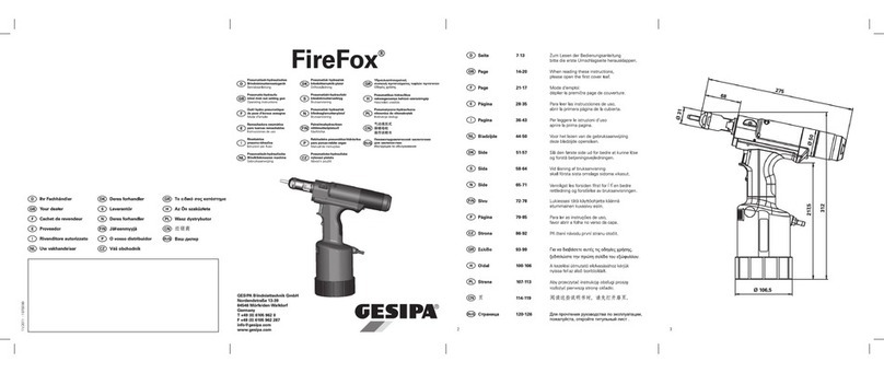
Gesipa FireBird Pro User manual

GESIPA Blindniettechnik GmbH
Nordendstraße 13-39
64546 Mörfelden-Walldorf
Germany
Akku-Blindnietmutternsetzgerät
Betriebsanleitung
Battery powered blind rivet nut setting
tool
Operating instructions
Outil de pose d‘écrous aveugles à batterie
Mode d‘emploi
Remachadora a batería de tuercas
remachables
Manual de instrucciones
Istruzioni per l‘uso
Accu-blindklinkmoerpistool
Handleiding
Üzemeltetési útmutató alkatrészlistával
Ledningsfrit blindnittemøtrik-
isætningsapparat
Brugsanvisning
Batteridriven blindnitmutterpistol
Bruksanvisning
Oppladbart batteri for pistol til setting
av blindnaglemuttere
Brukerhåndbok
Akkukäyttöinen niittimutterityökalu
Käyttöohje
Instruções de serviço
nýtovací matice
Návod k obsluze
T +49 (0) 6105 962 0
F +49 (0) 6105 962 287
FireBird® Pro / FireBird® Pro GE

3
1
2 3
4 5
AC
B
A
C
B
A
B C
E
D
G
F
G
H
x
y

4
Pos. Bezeichnung Abb.
A 1; 3; 4
B Mundstück 1; 3; 4
C Kontermutter 1; 3; 4
D Aufhänger 2
E Sicherungsschraube 2
F Abdeckung 2
G Display 1; 3
H Beleuchtung 3
I Schalter
J Schieber
x 4
Item Description Fig.
A Threaded mandrel 1; 3; 4
B Nosepiece 1; 3; 4
C Lock nut 1; 3; 4
D Hanger 2
E 2
F Cover 2
G Display 1; 3
H Lighting 3
I
J Slide
x Threaded mandrel length 4
Pos. Désignation Fig.
A 1; 3; 4
B Embouchure 1; 3; 4
C Contre-écrou 1; 3; 4
D Écrou de réglage 2
E Vis de sécurité 2
F Couvercle 2
G Écran 1; 3
H Éclairage 3
I Interrupteur
J Piston de contrôle
x 4
Pos. Denominación Fig.
A Vástago 1; 3; 4
B Boquilla 1; 3; 4
C Contratuerca 1; 3; 4
D Anillo de suspensión 2
E Tornillo de retención 2
F Tapa 2
G Pantalla 1, 3
H Iluminación 3
I Interruptor
J Pasador
xLongitud del vástago 4
Pos. Designazione Fig.
A 1; 3; 4
B Bocchello 1; 3; 4
C Controdado 1; 3; 4
D Gancio di sospensione 2
E Vite di sicurezza 2
F Protezione 2
G Display 1, 3
H Illuminazione 3
I Interruttore
J Spintore
x
Lunghezza mandrino
4
Pos. Naam Afb.
A Draadspindel 1; 3; 4
B Mondstuk 1; 3; 4
C Contramoer 1; 3; 4
D Ophangoog 2
E Borgschroef 2
F Afdekking 2
G Display 1, 3
H Verlichting 3
I Schakelaar
J Schuif
xDraadspindellengte 4

21
GB
Table of Contents
1. FireBird® Pro GE / FireBird® Pro GE blind rivet nut setting tool ........................22
1.1 Working range ............................................................................................22
1.2 Equipment / accessories ............................................................................22
1.3 Technical data ............................................................................................23
1.4 Safety instructions ......................................................................................23
1.5 Start-up .......................................................................................................24
1.6 Lighting .......................................................................................................24
1.7 Maintenance ...............................................................................................24
1.8 Storage .......................................................................................................24
2. Functional principle ...........................................................................................25
2.1 Replacement of the threaded mandrel (Fig. 3) ...........................................25
.................................................25
2.3 Adjusting the setting force ..........................................................................25
2.4 Saving and loading the setting force ..........................................................27
...................................................................27
....................................................28
2.7 Setting a blind rivet nut ...............................................................................28
3. Troubleshooting ................................................................................................29
.................................................................29
..................................................................29
3.3 Set blind rivet nut is not completely set ......................................................29
......................................................................................29
3.5 Repairs .......................................................................................................30
4. Warranty ...........................................................................................................31
5. Declaration of conformity ..................................................................................31

22
GB
1. FireBird® Pro GE / FireBird® Pro GE blind rivet nut setting tool
1.1 Working range
FB = FireBird® Pro
FB GE = FireBird® Pro Gold Edition
1.2 Equipment / accessories
Nosepiece / threaded mandrels
for FB Pro
M4, M5 in accessory magazine
for FB Pro GE
M8, M10 in accessory magazine
Hanger Concealed in housing
Quick charger 110 V (USA) or 230 V (EU) / 50-60 Hz
Quick-change battery 18.0 V / 2.0 Ah
Scope of delivery
2x double open-ended spanner
WAF 24/27 Quick-setting guide Article No. 1699983
Setting force guide Article No. 1699984
Operating instructions
M3 M4 M5 M6 M8 M10 M12
Alu FB
FB GE
FB
FB GE
FB
FB GE
FB
FB GE
FB
FB GE FB GE FB GE
Steel FB
FB GE
FB
FB GE
FB
FB GE
FB
FB GE
FB
FB GE FB GE FB GE
Stainless
steel
FB
FB GE
FB
FB GE
FB
FB GE
FB
FB GE FB GE FB GE -

23
GB
1.3 Technical data
Weight approx. 2.4 kg (incl. 2.0 Ah rechargeable battery and nosepiece/man-
drel magazine)
Max. setting stroke 10 mm
Drive Brushless DC motor
Tensile strength 15 kN for FB Pro
20 kN for FB Pro GE
Noise emissions LPA 76.5 dB (A), measurement uncertainty K = 3 dB
Vibration < 2.5 m/s², measurement uncertainty K = 1.5 m/s²
1.4 Safety instructions
Caution: The tool is not suitable for use in an ATEX zone.
The following safety rules must be observed to ensure adequate protection against
• The blind rivet nut setting tool is intended solely for the purpose of setting blind rivet nuts
and blind rivet studs!
•
•
•
range.
•
storage.
• Ensure that the battery is properly secured in the grip.
•
•
• Do not use the blind rivet nut setting tool as a hammer.
•
• -
mended (e.g. protective clothing, gloves, safety helmet, non-slip shoes, hearing protec-
tion or fall protection).
• The air inlets for the motor must not be obstructed; do not insert any objects into them.
•
• Use only genuine spare parts for repair.
• Repairs must be carried out only by skilled personnel. In case of doubt, send in the blind
rivet nut setting tool to the manufacturer.

24
GB
1.6 Lighting
-
— Continuous light/torch function:
Zero position::
-- Work light:
•
1.7 Maintenance
mandrels and nosepieces, as necessary (see section 2.1 for replacement of the threaded
mandrels).
Regular maintenance will extend the service life of your high-quality GESIPA® tools
which should be serviced at least every 2 years by an authorised workshop or by
GESIPA® Service. We recommend servicing of tools subject to intensive use at shorter
intervals.
1.8 Storage
1.5 Start-up
Important!
• Insert fully charged battery into the blind rivet nut setting tool in the correct position.
• Use a threaded mandrel and nosepiece size matching the size of the blind rivet nut.
•

25
GB
2. Functional principle
2.1 Replacement of the threaded mandrel (Fig. 3)
• Remove the battery from the tool.
• Loosen lock nut C using a double open-ended spanner (WAF 24/27).
•
•
•
•
•
2.2 Adjusting the threaded mandrel length “X“
• Loosen lock nut C.
•
• Fully utilise the thread depth of closed blind rivet nuts (Figure 4).
•
to prevent it from turning.
2.3 Adjusting the setting force
The setting force to be set depends on the blind rivet nut size and blind rivet nut material, and
on the materials to be riveted (material, hole diameter, material thickness).
1. Select the setting value from the quick setting guide
2. Set the selected setting value on the display
1. Select the setting value from the quick setting guide
The appropriate numerical value can be selected in the quick setting guide, depending on the
blind rivet nut size and blind rivet nut material.
(e.g. M5 - steel Guide value for the setting force 45)
These guide values have been determined using GESIPA® blind rivet nuts.

26
GB
2. Set the selected setting value on the display
Remove cover F, then set the selected value on the display G by pressing the plus or minus
buttons. Pressing the plus button increases the numerical value. Pressing the minus button
-
merical value changes in increments of 10.
The setting force of the riveting tool is increased by increasing the numerical value on display
G; the setting force is reduced by reducing the numerical value.
Important! As the setting behaviour can vary, depending on the blind rivet nut type, manufac-
turer or material thickness, a setting trial is recommended before riveting the selected part.
This should - if possible - be carried out on the original part.
Blind rivet nut not completely set
Increase the setting value in small increments
Blind rivet nut set with excessive force
- Threaded mandrel bent or broken
Reduce the setting value Blind rivet
Nut correctly set
- Closing head completely formed, thread not damaged
After adjusting the setting value, carry out a further setting trial and assess the setting result.
Important! If the correct setting value is not known or if in doubt, always start with
lower values in order to avoid damaging the tool!
M3 M4 M5 M6 M8 M10 M12
Alu 03 10 20 40 45 50 90
Steel 10 40 45 60 75 90 98
Stainless
steel
15 30 50 85 95 98 -

27
GB
2.4 Saving and loading the setting force
The FireBird® Pro (GE) is able to save the set force value to its integrated program memory
Save the numerical values as follows:
• Determine and set the numerical value to be programmed (see section 2.3).
•
memory (initial value P0) in order to save a set numerical value.
• A program memory location from P0 to P9 can be selected by pressing the plus or minus
• button.
• -
play once more.
Previously saved numerical values can be called up as follows:
•
seconds (> 2 sec.) calls up the program memory.
•
plus or minus button.
• Holding the S button pressed again (> 1 sec.) loads the selected program and the corres-
ponding numerical value is displayed.
The load or save sequence can be cancelled at any time by pressing the plus and minus
buttons at the same time (> 2 sec.).
2.5 Screwing on the blind rivet nut
• Place the blind rivet nut onto threaded mandrel A straight.
• -
lify threading in of threaded mandrel A.
•
•
-

28
GB
2.6 Manual unscrewing of the blind rivet nut
•
of the blind rivet nut or threaded mandrel 1 is defective;
• -
ring.
after removing the accessory magazine (Figure 5), if necessary. Carefully loosen threa-
value as described in section 2.3.
2.7 Setting a blind rivet nut
•
rivet nut setting tool.
• -
• Important!
If the set numerical value is not reached during the setting operation, the setting operation
operation, the last numerical value set appears on the display G again. If the blind rivet nut
is not reset, quit rS mode by pressing the S button (>1 sec).
• Important!
(reWork). To do this, select the correct numerical value for the setting force (see section
2.3). Then hold the S button pressed until the program memory P0 - P9 has been skipped
numerical value. Press the S button again to bring the tool back to normal mode.

29
GB
3. Troubleshooting
3.1 Blind rivet nut is not screwed on
Possible causes Corrective measures
Nut thread defective
Threaded mandrel defective Replace threaded mandrel (section 2.1)
Nut does not rest against nose-
piece
Threaded mandrel length x incorrect; adapt to nut length (section 2.2)
Battery is discharged
Error indicated on the display E4
Charge the battery
3.2 Blind rivet nut is not unscrewed
Possible causes Corrective measures
Nut thread deformed due to excessive setting
force
Reduce the setting force (section 2.3); remove
Nut thread completely destroyed. Error indicated
on the display E1
-
ledge the error (section 2.4)
3.3 Set blind rivet nut is not completely set
Possible causes Corrective measures
Set the correct numerical value (section 2.3)
Set numerical value not reached or setting stroke
too short.
Error indicated on the display E1
Reset the blind rivet nut in ReSet mode (section
2.7)
-
ted on the display E2
Battery is discharged
Error indicated on the display E4
Charge the battery
Possible causes Corrective measures
Battery is discharged Charge the battery
destroyed due to excessive setting stroke (rapid
Reduce setting stroke (section 2.3)

30
GB
-
ries (e.g. extension units, angle heads) are used, it is mandatory to carry out a manual referen-
ce run before using the tool again!
1. Ensure that the tool is ready for operation and that all required attachments are correctly
mounted on it, then insert the battery.
2. Turn LED ring to • zero position.
3.
4.
5. Hold the trigger pressed for a further 10 seconds until the tool beeps 3x.
6.
7.
After this reference run, start operation as described in section 1.5. Starting operation after a
rivet nut setting tool.
3.5 Repairs
-
riod should only be carried out by skilled technical personnel. Failure to observe the assembly
and setting instructions and operation by non-skilled personnel may result in serious damage
to the supplier or to GESIPA®.

31
GB
4. Warranty
gesipa.com/agb shall apply.
and health requirements of the EC directives. Any modification of the device not approved by
supplied must be observed. This document must be available at all times.
FireBird® Pro
FireBird® Pro Gold Edition
•
•
•
•
•
•
•
•
•
•
•
• 2012/19/EU
• 2011/65/EU
• 2006/42/EG
• 2014/35/EU
• 2014/30/EU
GESIPA Blindniettechnik GmbH
Nordendstraße 13-39
64546 Mörfelden-Walldorf,
Germany
5. Declaration of conformity
pp. Dipl.-Ing. Stefan Petsch
Head of Operations Tools Member of
Division Management

01/2022 - 1679838
Ihr Fachhändler
Cachet du revendeur
Vendedor autorizado
Rivenditore autorizzato
Uw vakhandelaar
Az Ön szaküzlete
Dystrybutor
Deres forhandler
Din återförsäljare
Deres forhandler
Jälleenmyyjä
O vosso distribuidor
Other manuals for FireBird Pro
4
This manual suits for next models
1
Table of contents
Other Gesipa Power Tools manuals

Gesipa
Gesipa FireFox2 User manual

Gesipa
Gesipa Taurus 7560001 User manual

Gesipa
Gesipa PowerBird Guide

Gesipa
Gesipa AccuBird Pro Guide

Gesipa
Gesipa FireBird User manual

Gesipa
Gesipa FireBird Guide

Gesipa
Gesipa FireFox User manual

Gesipa
Gesipa PowerBird Guide

Gesipa
Gesipa FireBird Pro S GE User manual

Gesipa
Gesipa taurus 1 User manual