Nakanishi NLS-110 User manual

1
Thank you for purchasing the LUSTER NLS-110. It is designed for polishing, lapping and
honing after metal mold machining. Please read this operation manual carefully before use.
qUse a protective cover, glasses and/or facemask for your safety during usage.
wDo not touch the bur-holder, tool, etc. while it is in a reciprocating motion.
e
Do not drop or hit LUSTER, because the shock could damage the internal components.
rCheck if the tool/file has been mounted firmly, before operation.
tDo not force the tool/file to overload, or the
LUSTER
may be damaged.
yOverloading LUSTER could activate the protective circuit.
u
Be sure to keep LUSTER/motor away from water. It could cause an electric shock to the operator.
i
Do not lubricate LUSTER/motor or any bearings in the system, as grease-filled bearings are used.
oThe LUSTER NLS-110 is powered by the Emax EVOlution control unit NE249.
(Never connect to Emax control unit NE129)
1Cautions on handling
NLS-110
LUSTER
Warning
•
Do not exceed the " Maximum Allowable Motor Rotation Speed " (Refer to " Specifications ").
•
When sensing that the LUSTER and motor are overheated during operation, reduce the
working force or the motor rotation speed, or stop the operation until the LUSTER
cools down before restarting.
OM-K0607E 001
3

2
qRepeated or long-term exposure to excessive vibration may cause temporary or
permanent physical injury, particularly to the hands, arms and shoulders.
wIt is strongly recommended that anyone using vibrating equipment, such as
power hand tools, first be physically examined by a doctor and then have regular
medical check-ups to make sure the user does not have any medical problems
that are being caused or worsened by using vibrating equipment.People who
have impaired blood circulation to the hand, past hand injuries, nervous system
disorders and Raynaud’s disease should not use vibrating equipment.
e
If you feel any medical or physical symptoms related to vibration (such as tingling,
numbness and white or blue fingers), report the situation to your employer and
seek medical advice as soon as possible.
rAvoid smoking while using vibrating equipment, as nicotine reduces the blood
supply to the hands and fingers.
tSuitable gloves should be worn to reduce the vibration effects on the user.
yTools with the lowest vibration should be used when there is a choice between
different processes.
uWork schedules should be arranged to include vibration-free periods throughout
each day.
q
LUSTER should only be used after reading and understanding the Operation Manual.
wGrip LUSTER as lightly as possible (while still keeping safe control of it).
Let LUSTER do the work.
eTo ensure your safety, LUSTER should be maintained as explained in this
Operation Manual.
rDo not use LUSTER at vibration levels of 2.5 m/s2and higher.Select the
combination of motor speed and stroke so that the vibration level stays in the
shaded area as shown on the chart lower right.
tDo not use LUSTER with vibration at 2.5 m/s2or higher each day for an extended
period of time.
y
If any abnormal vibration occurs stop using LUSTER
immediately and return to NAKANISHI for service.
u
Do not exceed the motor speed of 30,000min
-1
(rpm) to
prevent trouble or damage.
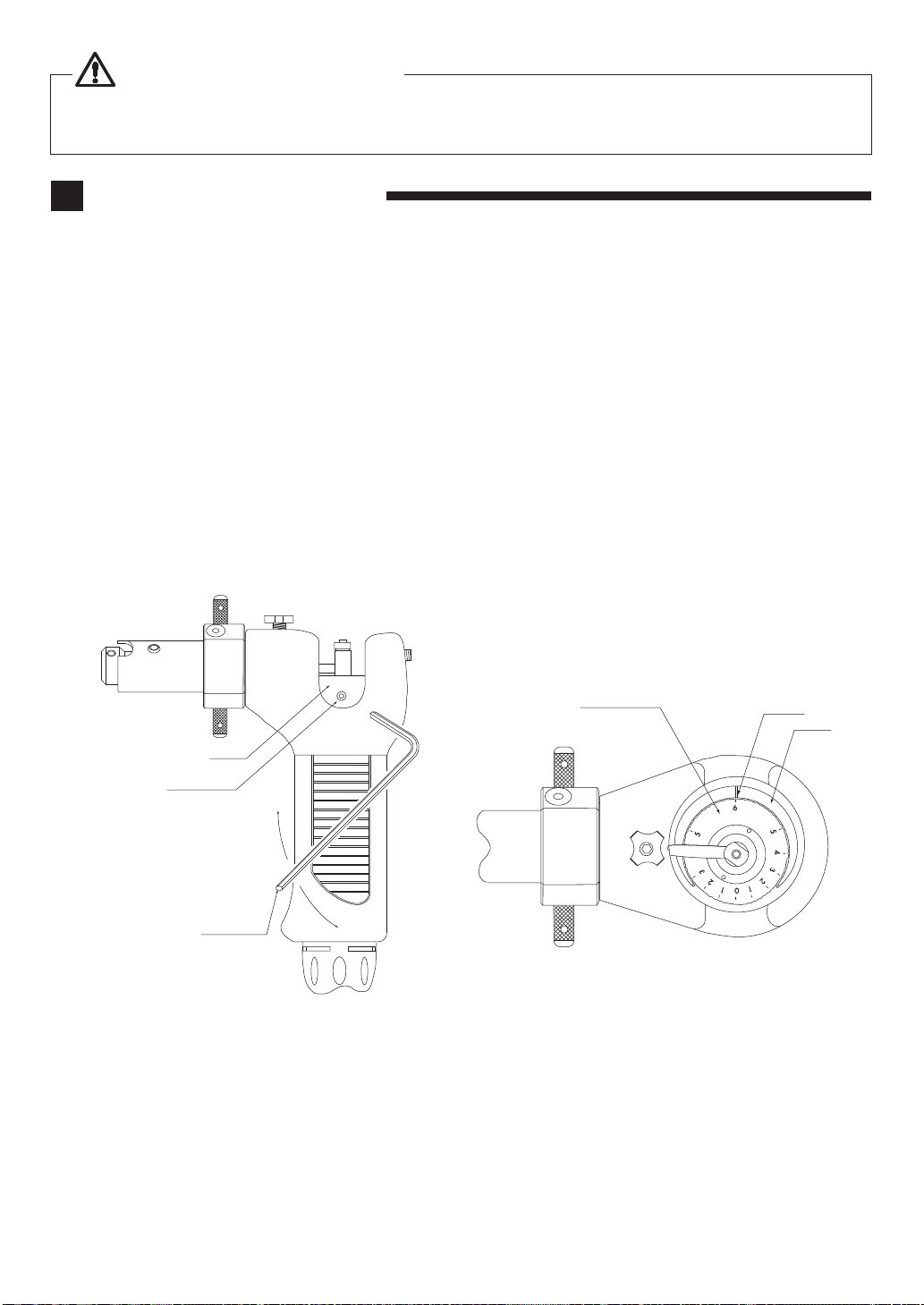
i
Remove the plug from the control unit when adjusting
the stroke length for safety reasons.
Caution on Vibration
General Warnings for All Vibrating Equipment
Additional Warnings for the Safe Use of LUSTER
0
5
10
15
20
25
30
35
40
123456
Stroke (mm)
Motor Rotation Speed ( x 103min-1(rpm))
(2.5 m / S2)(2.5 m / S2)
(Refer to Graph - 1).
Remove the plug from the control unit when adjusting
the stroke length for safety reasons.
Graph - 1

3
Features
qON/OFF of reciprocation movement is easily done at the grip.
wTools are easy to change.
eReciprocating speed and stroke can be easily and continuously controlled.
rYou can mount various files available on the market.
tMounted tool/file can be easily reoriented onto the work surface.
2
Specifications
3
LUSTER NLS-110 has a built-in motor. Insert the cord plug into the control unit as mentioned below.
•Align the cord plug with the jack of the control unit and push in. (Fig.1)
Connecting Control Unit
Adjusting Motor speed (Tool Reciprocating Cycle)
Adjust the motor speed at the control unit.
ON/OFF of the motor can be made either at the grip or at the control unit. (Fig.1)
(See the control unit operation manual for control by the switch on unit.)
•Motor stops when ON/OFF switch on the grip is depressed during operation.
•Push the switch on the grip again to re-start the motor.
4
5
Model NLS - 110
Maximum Allowable Motor Rotation Speed
Less than 25,000min-1 (rpm)
Stroke 0 - 6mm (0 - 0.236")
Reciprocating frequency 0 - 105 cycles / second
Applicable Control Unit Emax EVOlution
Weight (With Power Code) 800 g (28.2oz.)
Vibration Level Use the LUSTER less than 2.5m / s2(Refer to Graph - 1)
Noise Level at 1m distance Less than 70dB (A)
Temperature Humidity Atmospheric Pressure
Operation Environment 0 - 40°C MAX.75%
(No condensation) 800 - 1,060hPa
Transportation and Storage
Environment -10 - 50°C 10 - 85% 500 - 1,060hPa

4
Fig.2
Loosen
Tighten
Tool
Bur Holder
Tool mounting Setscrew
Hex Key(2 mm)
Allen Wrench
Dimensions and Parts Description
6
ȭ39.8
161
119
ȭ20
ȭ14.9
Head Cover Setscrew
Head Cover
Rubber Grip
Plug
Positioning Pin
Stroke Length Setscrew
Spindle
Handle
Guide Sleeve
Bur Holder
Stroke Length
Adjustment Ring
Motor ON / OFF
Switch
Tool Mounting
Setscrew
Lubrication
Port
Guide Sleeve
Positioning Screw
Guide Ball
Fig.1
•Mounting
qInsert a tool (less than ø3.2 mm) into the bur holder and tighten the tool mounting
setscrew with the supplied hex key (2 mm). (Fig.2)
wTo mount a larger tool (ø3.2 mm through ø6.4 mm), loosen the setscrew, remove the
bushing, insert the tool and tighten the setscrew. (To re-install the bushing, align the
guide ball on the bushing with the slot in the bur holder.) (Fig.3)
•Removing
Loosen the tool mounting setscrew with supplied hex key (2 mm), and remove. (Fig.2)
Changing the Tool or File
7
Allen Wrench (Fig.2).
Allen Wrench, and remove (Fig.2).
Fig.3
Bur Holder
Guide Ball
Bushing

5
Caution on Vibration
Remove the plug from the control unit before replacing tool, for your safety.
Check if tool/file has been tightened firmly, before operation.
Adjusting Stroke Length
qLoosen the head cover setscrew with the supplied hex key (2 mm) (Fig.1).
wSlide the head cover upward and remove. (Fig.1).
eLoosen the stroke length setscrew with the hex key (2 mm). (See fig.4)
rTurn the adjustment ring, while holding the spindle with your finger, and align the desired
stroke length with the indicator line. The stroke length can be adjusted between 0 - 6 mm.
(0 - 0.236")(Fig.5)
tTighten the stroke length setscrew with the hex key (2 mm). (Fig.4)
yInsert the head cover and push it down, aligning the guide groove on LUSTER and the
guide ball on the head cover.
uFasten the head cover setscrew with the hex key (2 mm) (Fig.1).
iChoose the motor speed in accordance with the stroke length as shown in chart below.
Operate LUSTER avoiding abnormal vibration.
8
Graph - 1.
Allen Wrench (Fig.1).
Allen Wrench (Fig.4).
Allen Wrench (See Fig.4).
(Fig.5)
Spindle
Stroke Length
Setscrew
Hex Key (2mm)
Tighten
Loosen
Fig.4
Allen Wrench
6
5
5
4
3
3
2
2
1
1
0
Stroke Length
Adjustment Ring Indicator
Spindle
Fig.5

6
Orientation of Guide Sleeve/Tool
Mounted tool can be re-oriented.
• Loosen the guide sleeve positioning screw to make the guide sleeve smoothly rotate. (Fig.6)
This can allow the tool to fit the work surface with ease.
• Fasten the guide sleeve positioning screw to fix tool. (Fig.6)
This completes re-orientation of the tool.
Caution
Remove the plug from the control unit when adjusting the stroke length for safety reasons.
9
Warning
•
Do not exceed the " Maximum Allowable Motor Rotation Speed " (Refer to " Specifications ").
•
When sensing that the LUSTER and motor are overheated during operation, reduce
the working force or the motor rotation speed, or stop the operation until the
LUSTER cools down before restarting.
3
6
5
5
4
3
3
2
2
1
1
0
Guide Sleeve Positioning Screw
Guide Sleeve
Lubrication Port
Tool
Oil Fig.6
Lubricate LUSTER at least once a day from the lubrication port as shown. (Fig.6)
In case the supplied oil depletes and NAKANISHI oil cannot be found, use the turbine oil
class 1 ISO VG32.
Lubrication
10

7
Applications
11
1.
Finishing the complicated shapes and sizes. (Fig.7)
(For press dies, Drawing dies, etc.)
qMachine by 0.05 mm.
wFile finish the clearance by 0.02 mm max.
eHeat treat.
rHone or lap the edges
tFinal polish by lapping or honing grindstone
yPolish the surface of dies
Dies
Vise
LUSTER
Fig.7
2. Finishing of grooves (Fig.8)
With use of proper tools that are supplied
with, finish the surface by filing, lapping, or
honing, and final polish.
Workpiece
LUSTER
FVA
NGA LKE-2A
FBA-2
Fig.8
Standard Accessories
VEA
Oil stone or large file can be used.
The stone angle can be changed.
VES
FVA
Spring in radial direction.
NGA Holder
Use with FBA-2, SEV.
FBA-2 Holder
Use with LIKE-2A.
56
31
ø3
25
3.5
ø3
45
66
6
16
2
Lubrication Nozzle
LKE-2A
Use with holders.
Use for lapping and horning as is.
Use with the sandpaper provided or other
polishing materials adhered on it.
57
•Sandpaper : K012
-
K100(rectangle) (4 different grit sizes) 10 pcs. each kind.
Rectangle sandpapers in variety of grits are available.
•Allen Wrench: 2
mm
,2.5
mm
,3
mm
•Oil
12

File
FVA
Typical use of Accessories
FBA-2 FVA
LKE-2A
FBA-2
NGA FVA
LKE-2A
FBA-2
NGA
LKE-2A
NGA
NGA
LKE-2A
FBA-2
VEA
NGA
Oil stone
Super stone
13
Troubleshooting
14
When the trouble is found, please check the following prior to consulting your dealer.
Trouble Cause Inspect / Corrective Action
Reciprocating stroke is poor Low lubricant Lubricate Oil properly
Guide Sleeve Slippage Guide Sleeve Screw improperly If the guide sleeve is slips after retightening,
send to NAKANISHI for repair.
Heat generation during rotation
Ball Bearing worm out by the reason Ground
Particles stock in the air of Ball Bearing
Send to NAKANISHI Repair
Abnormal Noise or Unusual
vibration during rotation
Ball Bearings worn due to debris particles
in the Ball Bearings
Ball Bearing worm out
Send to NAKANISHI Repair
Tool will not tighten The tool mounting setscrew has loosened Check if the tool mounting setscrew is
property positioned. Clean it and retighten.
Contents are subject to change without notice.
2015.11.20 0005
Table of contents
Other Nakanishi Power Tools manuals
Popular Power Tools manuals by other brands

infaco
infaco Powercoup PW2 EC1700 instructions

Parkside
Parkside PASSK 20-Li A1 Translation of the original instructions

Atlas Copco
Atlas Copco LMS68 GOR25 Product instructions

Makita
Makita 1911BJ instruction manual

Makita
Makita 3612 instruction manual

Ingersoll-Rand
Ingersoll-Rand QA6 series Product information