NAKAYA Tornado NK-125 User manual

Model Code
Attachable Blade
Cut Depth
Weight
Cutting Material
Dust Bag capacity
Proper Grinders
-1-
BOSCH
MAKITA HITACHI
NK-125
INSTRUCTIONMANUAL
WARNING
OVERVIEW
SPECIFICATIONS
・The supplied connecter may not connect securely to disc grinders. In this case, do not use TORNADO.
・TORNADO is for use when cutting concrete, stone and brick. Do not use when cutting metal or other materials.
Do not use with any other type of cutter, such as a grindstone or tipped saw.
・Always check TORNADO for damage, cracks or deformation before use.
Do not use TORNADO which is damaged, cracked or bent as this could lead to injury.
・Be sure to wear protective goggles, a dust mask, protective footwear, earplugs and other protective equipment when working.
・Keep TORNADO away from gasoline, thinner, petroleum and paraffin.
・Hold the workpiece with clamping devices.
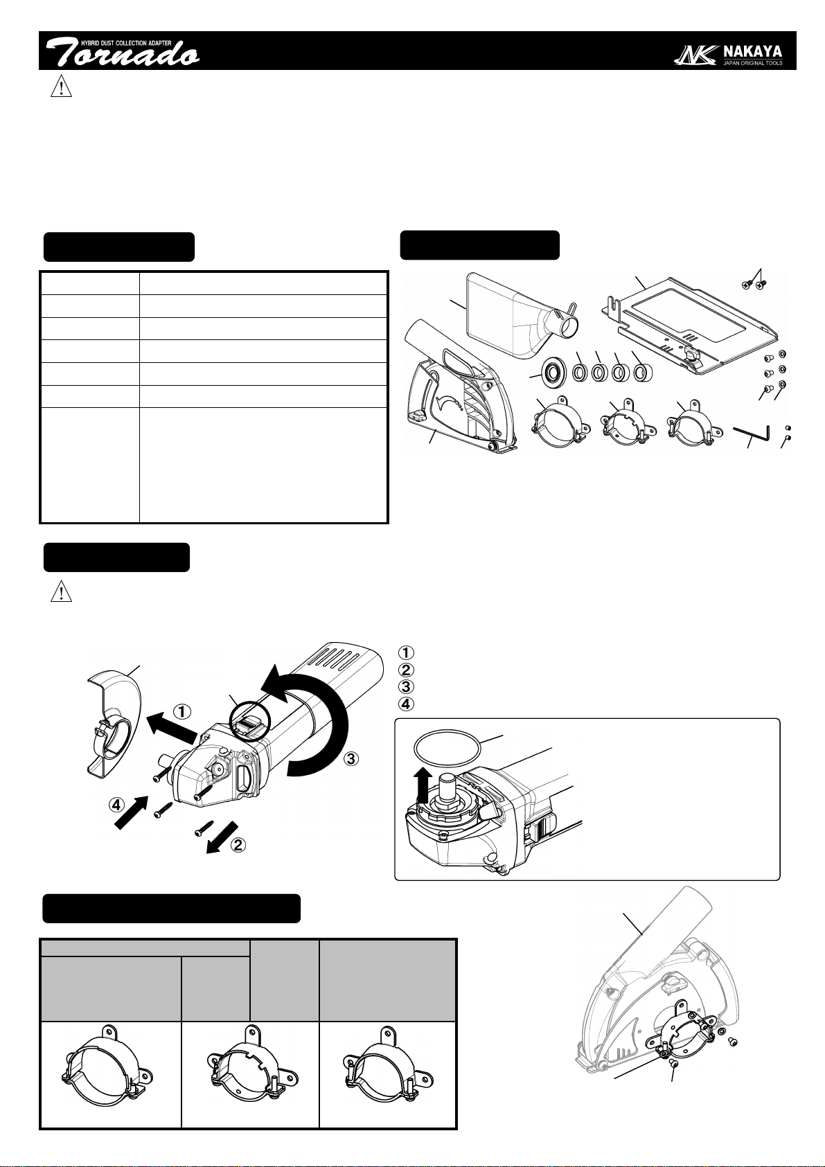
[a] Main Unit [b] Dust Bag [c] B-Connecter [d] M-Connecter
[e] H-Connecter [f] M4 Screw [g] Cup Washer [h] Spacer (T4.5)
[ i ] Spacer (T7.3) [ j ] Spacer (T9.4) [k] Spacer (T12.6) [m] Base Flange
[n] Foot Plate [p] Flat Screw [q] Wrench [r] Setscrew
PREPARATION
WARNING
Guard
SW
Take the Guard off.
Remove the Screws.
Turn the Grinder Body to locate the SW upper position.
Tighten the Screws.
CONNECTERINSTALLATION
[c] B-Connecter [d] M-Connecter [e] H-Connecter
[a] Main Unit
[f] M4 Screw
[g] Cup Washer
Choose the proper connecter and fit it to [a] Main Unit
with [f] M4 Screw and [g] Cup Washer.
・Be sure to turn off the disc grinder and remove the plug from the electrical outlet before attaching TORNADO.
・If you attach TORNADO to a disc grinder but the connector is loose and cannot be securely attached, do NOT use TORNADO.
Using it in this state could lead to injury.
a
b
c
d
e
h
i
j
k
p
n
m
N300129
f
g
GWS6-115/GWS7-115(E)/
GWS8-115/GWS8-125/
GWS9-125/GWS10-125/
GWS11-125CI(E)/GWS14-125CI(E)(T)/
GWS15-125CIH(CIEH)(CITH)
9554NB/9558NB/GA4530/9565CV
G12SS/G12SR3/G13SR3/
G13SB3/G13SE2
BOSCH:
MAKITA:
HITACHI:
GWS8-115/GWS8-125
GWS10-125/GWS11-125CI
GWS14-125CI(E)(T)
GWS15-125CIH(CIEH)(CITH)
GWS6-115
GWS7-115
GWS9-125
GWS8-115/GWS8-125/GWS10-125/
GWS11-125CI/GWS14-125CI
Remove O-Ring
if it is equipped.
O-Ring
NK-125
125mm/T1.5-2.2 Diamond Blades.
5-30mm
520g (Main Unit)
Concrete, Block, Stone, Tile, ..etc.
Should be epmtied with every 3m of cutting.
q r

[Requiring Spacer]
MAKITA
GWS6-115 G12SS G12SR3 G13SB3
GWS7-115 G13SR3 G13SE2
-2-
BOSCH
HITACHI
[ h ] Spacer
[ k ] Spacer
[ j ] Spacer
T12.6
T4.5
T9.4
T7.3
[ i ] Spacer
FIT TO GRINDER
N G
Hold
Hold the top of the Main Unit and tighten
the screws.
* Confirm NO tilt in Grinder.
* Adjust the angle of Grinder so as to make
the bottom surface flat.
* G13SB3/SE2 need [n] FOOT PLATE.
==>Refer to Page4.
BLADE INSTALLATION
Wrench
Blade
[m] Base Flange
1. Loosen Knob Bolt and open [a] Main Unit.
2. Set the proper Spacer [h-k] into the Spindle.
3. Set [m] Base Flange on the Spacer.
4. Set the Blade on [m] Base Flange.
5. Set the Wheel Nut on the Blade.
(Be care of the direction of Wheel Nut)
6. Fix the spindle and tighten the Wheel Nut.
7. Confirm NO contact between the Blade and inner
area of the Main Unit.
Spindle
Knob Bolt
WARNING
Make sure TORNADO is securely
attached, otherwise it may come loose,
causing injury.
Wheel Nut direction
BOSCH
OTHERS
[a] Main Unit
GWS8-115/GWS8-125
GWS9-125/GWS10-125
GWS11-125CI/GWS14-125CI
GWS15-125CIH(CIEH)(CITH)
9554NB
9558NB
GA4530
9565CV
O K
O K
N G
* G13SB3/SE2 need
[n] FOOT PLATE.
==>Refer to Page4.
BOSCH GWS6-115 / GWS7-115
After fitting, tighten [r] Setscrews into [d]
M-Connecter by [q] Wrench.
[q]
[r]
Do NOT over tighten [r] Set
screws or they could cause
damage or deformation to the
Grinder and Connecter.
[d]

-3-
CUTTING(SELFVACUUM)
N G
O K N G
Surely close the Main Unit and tighten the Knob Bolt.
Confirm NO opening at the back side.
N G N G
CUTTING
DIRECTION
Rotating direction
Surely connect [b] Dust Bag to the duct,
then turn the Grinder on and start cutting.
Dust Bag should be emptied with every 3m of cutting.
[CAUTION]
1. Confirm the direction of cutting and Blade rotation.
2. Keep NO gap between the material, otherwise the
dust should leak out from the bottom.
3. Keep closing the Base, otherwise the dust should
leak out from the opening.
4. Do NOT use worn-out blade, otherwise the dust
collection performance should be dropped off.
5. Confirm that the fastener of the Dust Bag is
securely closed.
6. Do NOT wash the Dust Bag.
[b] Dust Bag
Insert deeply
Duct
Base
CUTTING
DIRECTION
Rotating direction
CUTTING(WITHCLEANER) Surely connect Cleaner Hose to the duct of Main Unit,
then turn Grinder/Cleaner on and start cutting.
[CAUTION]
1. Confirm the direction of cutting and Blade
rotation.
2. Keep NO gap between the material, otherwise
the dust should leak out from the bottom.
3. Do NOT use worn-out blade, otherwise the
dust collection performance should be drop off.
4. Use proper adapter between Duct and Hose.
(Duct diameter : 34mm )
Close
Knob Bolt
Duct

DEPTHADJUSTMENT
Base Line
Scale
Knob Bolt
Cut Depth
1. Loosen the Knob Bolt.
2. Set the Base line with the Scale line of
requiring cut depth.
3. Tighten the Knob Bolt.
[CAUTION]
(1) Surely connect with Cleaner, otherwise the
dust can not be collected.
(2) Use the scale just for a reference.
Base
FOOTPLATEINSTALLATION
*G13SB3/SE2 need [n] Foot Plate to offset the
projecting of Gear Case of the Grinder beyond
the bottom surface.
1. Complete the installation of Grinder and Blade.
2. Loosen the Knob Bolt.
3. Set the Main Unit on [n] Foot Plate.
4. Tighten Knob Bolt.
5. Tighten [p] Flat Screws from the bottom
surface, with the Front Guide matched with
the groove of the Foot Plate.
[CAUTION]
Blade Change and Depth Adjustment is
impossible when using with Foot Plate.
Connect Dust Bag or Cleaner to the duct.
T-Guide (Bar 12 x 3) is adaptable.
*T-Guide : Optional.
T-Guide
Knob Bolt
[p] Flat Screw [n] Foot Plate
groove
Front Guide
Gear Case
-4-
Other NAKAYA Dust Collector manuals