NANHUA FR15 Series User manual

Shanghai Nanhua Electronics Co., Ltd Tel:+86 021-39126868 Fax:+86 021-39126868ext 808/818 Web:www.nanhua.com E-mail:sales@nanhua.com Add: Building 9, No.
1755Wenbei Rd, Jiading district Shanghai 201802
All rights reserved by Nanhua,without the written authorization of the Nanhua, any part thereof shall not be reproduced or transmitted in any form.
FR15 S
y
nchronizin
g
Control Box
FR1
5
-
E
3
-V1
2
1 /3
Application
Design for the fault alarm output,ON/OFF and flash frequency control for aviatioon obstruction light.
Major functions&features
• Control the aviation lights flash synchronously.
• With fault alarm function. When any light fails, there will be with alarm indicator and fault signal
output.
• Alarm signal is relay contactor output, no power source.
• With photocell/manual switchover device. If you do not need photocell function, it could change
to manual control model by this device.
•• Light-operated switch use PJ003 to realize its function. Fault alarm function about photocell can
be customized.
• AC type control box can customize the GPS synchronization: Synchronize all aviation lights
which are controlled by different control box.
• With disturbance switching function. When lead light fails, standby light will switch on
automatically.(Customized).
Specification
Voltage DC48V
AC110V~AC240V Control method Steady burning/flash
Control circuit
branch 4 ways Flash frequency 20~60 times/minute
(adjustable)
Photocell sensitivity 70~100Lux(on/off) Alarm output dry connect(relay) output
Ambient
temperature -30˚C ~ +70˚C IP code IP65
Humidity 10% ~ 95% (no coagulation)
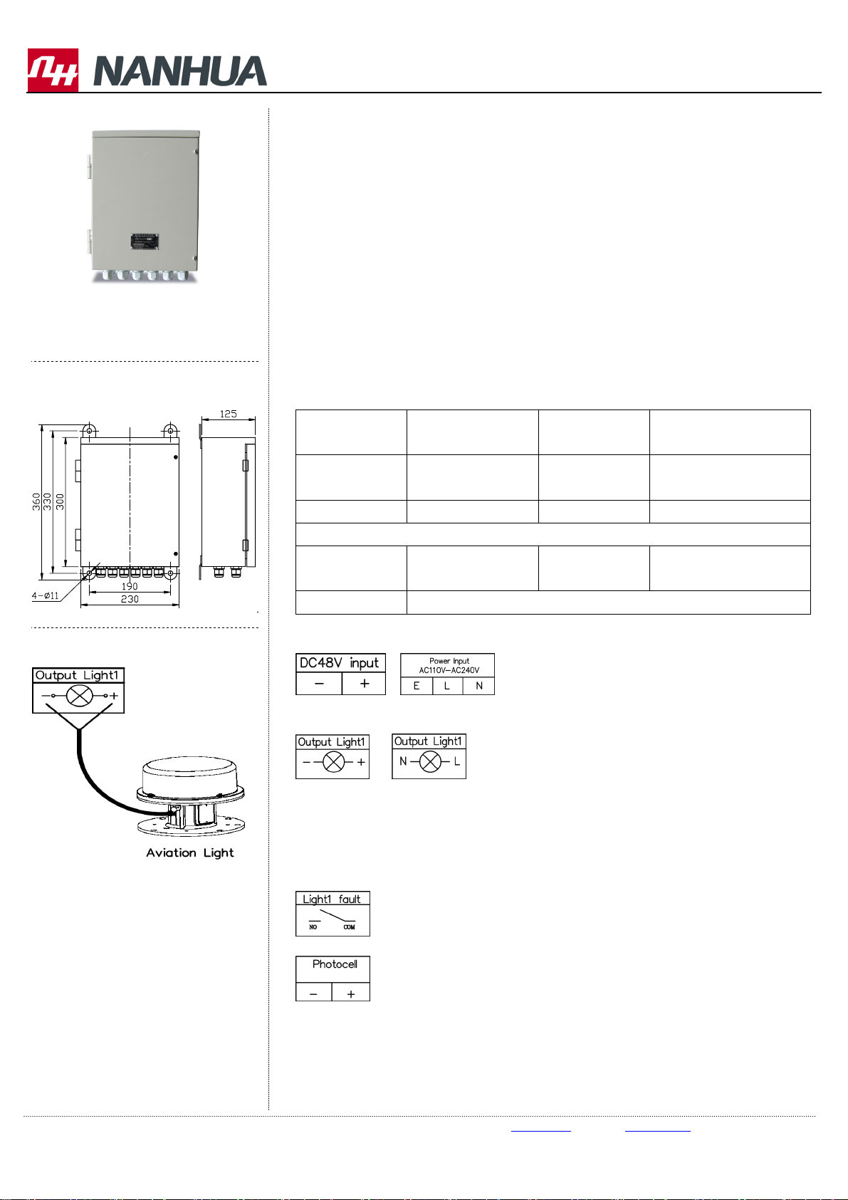
Wiring Connection
•Power connetion terminal. Product has AC and DC type. Please see the following diagram:
•Aviation light’s connction terminal. Product has AC and DC type. Please see the following
diagram:
For control box with faulty switch over function, Light 1 is lead light’s outputting, Light 2 is
standby light’s outputting. When Light 1 works, Light 2 is rest. In case Light 1 fails, Light 2
start to work automatically.
•• Connection terminal of aviation light’s faulty alarm. When light fails, this terminal will be
closed. Following diagram is “Light1 fault” terminal.
• Please see following diagram for photocell connection terminal.
Operation:
• Manual/Automatic switchover:
Set the dial switch to the left side, the control panel is in auto status. In this case, control
box will switch on/off the lights at nighttime/daytime automatically. Set the dial switch to
the middle, control box is in manual status. In this case, the lights will work. Set the dial
Installation(unit:mm)
Connection diagram
FR15 Series Outdoor

Shanghai Nanhua Electronics Co., Ltd Tel:+86 021-39126868 Fax:+86 021-39126868ext 808/818 Web:www.nanhua.com E-mail:sales@nanhua.com Add: Building 9, No.
1755Wenbei Rd, Jiading district Shanghai 201802
All rights reserved by Nanhua,without the written authorization of the Nanhua, any part thereof shall not be reproduced or transmitted in any form.
FR15 S
y
nchronizin
g
Control Box
FR1
5
-
E
3
-V1
2
2 /3
Accessory:photocell
PJ003
Inside picture
Application
switch to the right side, control box is in manual status. In this case, the lights will be off.
•• Steady burning/flashing mode switchover, and flashing rate setting:
DC type:
Set it by dial switch. When 2 dial switch is in “ON” status, aviation light is steady burning.
Otherwise, aviation light is flashing. Flashing rate 20\40\60 FPM is optional. Please see
following diagram:(FPM = FLASH PER MINUTE)
AC type:
The 4 dial switches on the left side control 1-4 aviation light separately.
When dial switch is in “ON” status, aviation light is flashing. When dial switch is in “OFF”
status (digital), aviation light is steady burning.
Flashing rate could be 20/30/40/60 FPM, please see following diagram:
• GPS synchronization function(AC110V~AC240V optional ):
GPS synchronization is against aviation lights under control box (flashing mode) managing.
Meanwhile, all control boxes must be same flashing rate setting. It will receive signal
successfully after 10 minutes operation.
GPS antenna must be installed in open environment.
• Installation:
DC type control box:
Single channel to control aviation light flashing/steady burning is not available.
Recommendation: when control box connect different types of aviation light under steady
burning mode, the work mode should be controlled by aviation light. Or the steady burning
lights are controlled by control box and make them flashing.
AC type control box:
Single channel to control aviation light flashing/steady burning is available.
We recommend using steady burning lights. Flashing/steady burning is controlled by
control box.
We do not recommend using flashing lights. It my output alarm by mistake.

Shanghai Nanhua Electronics Co., Ltd Tel:+86 021-39126868 Fax:+86 021-39126868ext 808/818 Web:www.nanhua.com E-mail:sales@nanhua.com Add: Building 9, No.
1755Wenbei Rd, Jiading district Shanghai 201802
All rights reserved by Nanhua,without the written authorization of the Nanhua, any part thereof shall not be reproduced or transmitted in any form.
FR15 S
y
nchronizin
g
Control Box
FR1
5
-
E
3
-V1
2
3 /3
Light indicator instruction:
• Power:Power indicator
Manual:Manual status indicator
Auto:Automatic status indicator
• Light n Fault:Aviation light faulty indicator.
Light n ok:Aviation light normal indicator.
• GPS_POWER:GPS power indicator
1PPS:GPS receiving signal indicator. It will be flashing when it receive signal.
GPS_WORK:GPS working indicator. It will be flashing too when synchronization is running.
Notice
• This product is voltage detecting type , when and if the power of aviation light completely fails,
the control box will give an alarm. Suggest using for not high required test precision
• Don’t open any part of the products when operation.
Table of contents
Popular Control Unit manuals by other brands

Supermicro
Supermicro MicroBlade MBI-6118D-T2 user manual

ICP DAS USA
ICP DAS USA Zigbee ZT-2060 quick start guide

Telit Wireless Solutions
Telit Wireless Solutions E922-3GR Series Hardware user's guide

Samson
Samson 3354 Mounting and operating instructions

DMP Electronics
DMP Electronics Wiegand 734N installation guide

Cumberland
Cumberland Flex-Flo FLX-5350 Operation manual