CHANGING THE LENS
The lens is “sandwiched” between the front
case and a Lens Support Insert, which also
servesto hold the LED jewelinplace. Toinstall
one of the accessory lenses, proceed as fol-
lows.
1. Push up on the lower edge of the Lens
Support (see Fig. 3) until it is clear of its retain-
ers, then pull out the Lens Support from the
bottom. Be careful not to dislodge the LED
jewel. Note: If the jewel pops out, re-insert it
with the small index key positioned at the top.
2. Slide out the lens and install the replace-
ment correctly oriented.
3. Replace the Lens Support: Slip the Lens Support under the top lens
guides with its two tabs straddling the LED jewel, then push in at the bottom
until the Lens Support snaps into place.
WIRING
Removethewireentryhole(seeMOUNTINGTHE SENSOR)to gainaccess
to the terminal strip. (Be sure to caulk around the wires where they exit the
case; see previous Note.) Route wires to the terminal strip as shown in Fig.
4 and connect as follows:
Power (Terminals 1 [+] & 2 [–]). Apply 12Vdc to Terminals 1 [+] and 2 [–].
The power source may be regulated or unregulated. Power should be
suppliedfromacontrolpanelorotherpowersourceequippedwitharecharge-
ablebatterybackuptomaintainoperationintheeventofapowerfailure.Refer
to SPECIFICATIONS for power-supply requirements.
Alarm Relay (Form A) Contacts (Terminals 3 & 4). These contacts are
rated at 100mA, 24Vdc and are normally closed. When the sensor is operat-
ing,eitherdetectionofan intruderorlossofpowerwillcausetherelaycontacts
to open. (This mode of operation is required in UL installations.)
Alarm Relay (Form C) Contacts (Terminals 3, 4 &5). These contacts are
ratedat 100mA, 24Vdc.Terminal 4is common. Terminal3 isnormallyclosed;
Terminal 5 is normally open. When the sensor is operating, either detection
of an intruder or loss of power will cause the relay to trip. (In UL installations,
normally-closed terminals (3 and 4) must be used.)
Status (Form-A Version only) and Trouble (Where equipped)
Wiring to Terminals 5 (Status) and 6 (Trouble) are only required if using the
specialfeaturesof thisunit. Refer toADVANCED FEATURES andthe Wiring
Diagrams at the back.
Status Input (Form-A Version only, Terminal 5). Connect to the Status
terminal (Arm Lug) of the control panel. A low at Terminal 5 tells the sensor
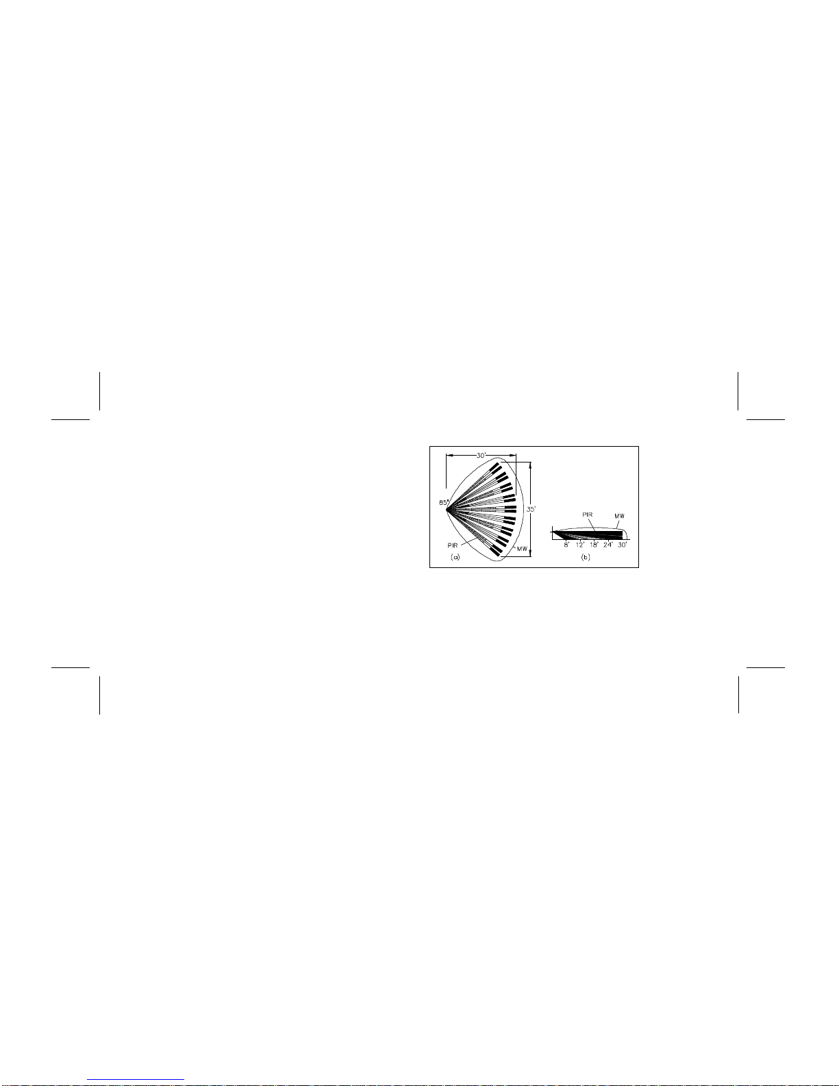
Fig. 3. Removing the
8