NAPCO GEMC-BSLC-PIR User manual

1
SPECIFICATIONS
Coverage (L x W): 50 feet x 50 feet (15.2m x 15.2m) at 68°
F (20°C), typical (with High Sensitivity Jumper "SEN" in-
stalled) 30 feet x 35 feet (9.1m x 10.6m) at 68°F (20°C),
typical (with Normal Sensitivity)
Operating Temperature: 14°F to 120°F (-10° to + 49°C)
Mounting: Wall or corner, 6 - 12 feet (3.6m) max.
High Temperature Set Point: 90°F +/- 4°F
Low Temperature Set Point: 40°F +/- 4°
RATINGS
Electrical Ratings
Input Power: 13.6-16.3VDC (supplied by GEMC-
BSLC module), 19mA.
Output Power: (not applicable)
Maximum Wiring Length: 2000 feet (#16 AWG). Re-
fer to GEMC-BSLC documentation for complete wiring
information.
Unit shall be connected to model GEMC-BSLC which is
employed in the GEMC C-Series control panel which is
provided with a minimum of 4 hours standby on battery
power.
PHYSICAL
Dimensions (HxWxD): 3.3in x 2.5in x 1.9in (8.4cm x 6.4cm
x 4.8cm)
Shipping Weight: 5oz. (142g)
FEATURES
•Advanced Microprocessor-based circuitry
•Utilizes Analog to Digital Signal Conversion
•Unique Passive Adaptive Algorithm optimizes detection
•Exclusive Detect & Compare Imaging Diagnostics D.C.I.D.
•True Room Temperature Measurement provides accurate
sensitivity and Room-Temp Alert Features
•Selectable sensitivity
•40 Element Stacked Array Lens eliminates detection hot
spots
•Look Down/Creep Zones provides coverage beneath sen-
sor
•Small Pet and Rodent Immunity (20lbs. maximum) (Not
evaluated by UL)
•Dual Mode Multifunction Trouble Output (Temp Alert-Self
Test)
•Low Temperature Alert for Heating System Monitoring (a
Patented Feature) signals panel if temperature drops below
40°F in the premises
•High Temperature Alert for Cooling System Monitoring (a
Patented Feature) signals panel if temperature rises above
90°F in the premises
•Unique circuit design protects against false alarms due to
radio-frequency interference
•Vertical and horizontal aiming capabilities
•Small size with ample wiring space
•Flat or Corner mountable to 12 feet
•Swivel bracket for ceiling or wall mounting above 12 feet
(SVL2) (Not evaluated by UL)
•Bug Shield
LOCATING THE DETECTOR & SELECTING A LENS
First, choose the type of coverage that will be best for the
particular area you need to protect.
Standard Wide-Angle Lens
Corner mounting with this lens is preferred as it provides the
best overall coverage. Choose a corner where the path of
an intruder will most likely cross beams, as opposed to walk-
ing towards or away from them. This lens is intentionally
made with an 85 degree angle of view, to help prevent cur-
tains on windows from being in detection zones.
Sources of heat, such as radiators and space heaters, do
not usually pose a problem as long as hot air from them
does not blow directly onto the detector. One exception to
this is overhead radiant heaters, these produce very high
levels of infrared energy and can heat the unit at some dis-
tance. Mount the unit as far from these as possible. Do not
mount the unit where the sun can shine directly on it. Mount
it away from the direction of sunlight.
PASSIVE INFRARED SENSOR
GEMC-BSLC-PIR
INSTALLATION INSTRUCTIONS
WI1719 07/10
R
333 Bayview Avenue
Amityville, New York 11701
For Sales and Repairs, (800) 645-9445
For Technical Service, (800) 645-9440
Publicly traded on NASDAQ Symbol: NSSC
© NAPCO 2010
Standard Wide-Angle Lens (LENS109) Coverage Pattern
(a) TOP VIEW (b) SIDE VIEW
85o
6’
50’ 50’
LOOKDOW N
ZONE
Top View: Standard Wide Angle Lens (LENS109) corner mounted
PIR
85°
50 ft.

2
If you are protecting a typical room area which may include
small pets or rodents (no larger than 20 lbs. total weight),
the factory installed wide angle lens can be used. If pets will
be present locate the detector as high as possible (7 ft.
minimum) and avoid placement that would allow the pets to
get within 6 ft. of the detector. It may be necessary to mask
a zone with the supplied material if a staircase is close to the
detector and directly in a zone. It is also possible to adjust
beams laterally by sliding the lens and retainer horizontally
within its stops.
Pet-Alley Lens (LENS817) (Not evaluated by UL)
For larger pets use a Pet-Alley Lens (LENS817). This lens
provides the same pattern and coverage as the standard
Wide-Angle lens, but there are no lower zones. This creates
an unprotected "Pet Alley" in which a larger pet can freely
move about. The detector should be mounted at 5 to 6 ft.
with the board mounting height index set to 6 ft.
Barrier Lens (LENS818) (Not evaluated by UL)
For hallways, aisles or corridors use the Barrier lens,
sometimes referred to as a curtain lens (LENS818), will
provide the best solution. This lens stacks the elements to
form an efficient and effective wall that will detect anyone
crossing it while ignoring motion on either side of the
detector. The detector has a maximum range of 50 ft. with
this lens.
Long Range Lens (LENS840) (Not evaluated by UL)
For longer range coverage the Long Range Lens
(LENS840) will provide up to 100 feet of range with a single
pair of beams.Complete coverage pattern is included with
the lens.
MOUNTING
First, use a screw driver to carefully lift the lens cover from
the housing. Second, remove the circuit board from the
housing by removing the screw in the center of the board.
Note: the screw is attached to the circuit board and will not
separate when removed. Third, determine the wire entry
points on the housing. The housing provides four possible
wire entry points, two for surface wiring and two for hidden
wiring. Determine which entry is most convenient and
punch out or remove the thin plastic section. Fourth, mount
the housing to the wall. There are three mounting options to
choose from depending on the desired location: flat wall
mounting, corner mounting or using the swivel bracket
(SVL2) for ceiling and wall mounting where it is
advantageous to tilt or aim the unit along a wall. Note:
using two units on swivel brackets mounted side by side it is
possible to cover almost 180 degrees when mounted on a
flat wall. If using the swivel bracket refer to the instructions
with the bracket. For wall or corner mounting simply hold
the case in the desired location and using the supplied
screws push through the appropriate thin wall mounting
screw holes and attach the unit with two or four screws.
Note: Do not over tighten the screws as this can distort the
case and compromise the air seal of the unit, because not
all walls are flat and all corners are square. Reinstall the
circuit board and proceed to wire the detector.
WIRING & TERMINAL DESCRIPTIONS
Refer to the wiring diagram and terminal descriptions,
connect the appropriate wire to the corresponding terminal.
When you have finished wiring the terminals seal the
opening around the wire entry hole and any other unused
holes with the supplied sealer.
Power (Terminals 1 [S] & 2 [S]): Connect to the [S] and [S]
terminals on the GEMC-BSLC.
Side View: Pet-Alley Lens (LENS817) used for larger pets
5-6 ft. pet undected
Large Pet Avoidance
50 ft.
Top View: Barrier Lens (LENS818) used for hallways
50 ft.
GEMC-BSLC-PIR Circuit Board Detail
SS
6FT
12FT
HT LT SEN
TEMPERATURE
SENSOR
MOUNTING HEIGHT
SCALE (ALIGN WITH
INDEX IN CASE)
HEIGHT LOCK
SCREW
WALK TEST LED
LED
DISABLE
LOOK DOWN
LENS
INFRARED
SENSOR
REMOVE JUMPER
TO DISABLE LED
TAMPER SWITCH
SLC BUS
ENABLE TROUBLE
OUTPUT ON HIGH
TEMPERATURE
ENABLE TROUBLE
OUTPUT ON LOW
TEMPERATURE SENSITIVITY
OFF = NORMAL
ON = HIGH
WIRE ENTRY
KNOCKOUT
Side View: Standard Lens (LENS100) used for small pets
pet less than 20 lbs. only
7 ft.
min. avoid pet activity within 6 ft. of detector
Small Pet Avoidance
30 ft.

3
CONFIGURING THE GEMC-BSLC-PIR
Low Temperature Alarm for Heating System Monitoring
(a Patented Feature)
The GEMC-BSLC-PIR has the ability to activate a Low
Temperature Output in the case of the ambient temperature
falling below 40°F. This feature functions exactly the same
as if you had purchased a separate temperature switch.To
enable this feature, connect a jumper across pins LT and
wire the Trouble Output (terminal 5) into the positive terminal
of a zone programmed for 24 Hour protection. This output
signal will remain active for as long as the temperature
remains below 40°F, when the temperature rises several
degrees above this the output will reset .
High Temperature Alarm for Cooling System Monitoring
(a Patented Feature)
The GEMC-BSLC-PIR has the ability to activate a High
Temperature Output in the case of the ambient temperature
rises above 90°F. This feature functions exactly the same
as if you had purchased a separate temperature switch. To
enable this feature, connect a jumper across pins HT and
wire the Trouble Output (terminal 5) into the positive terminal
of a zone programmed for 24 Hour protection. This output
signal will remain active for as long as the temperature
remains above 90°F,when the temperature falls several
degrees below this the output will reset.
Note: If the unit is in a high or low temperature condition, the
LED will glow dimly instead of being completely turned off ,
this can be used to test the units temperature monitoring
feature. If it is desired to test the temperature monitoring
feature, it will be necessary to either trip the unit or wait
several minutes for the unit to measure the temperature,
because the room temperature is measured every 10
minutes or each time an alarm is tripped. You will need
freeze spray or a freezer to test low temperature or to test
high temperature a hairdryer will do. Heat or cool the
temperature sensor (refer to Circuit Board Detail), then trip
the unit, assuming it hasn't done that already and let it settle
and observe the LED for a dim glow.
LED Disable Jumper
To prevent the walk test LED from turning on, remove the
jumper from the pins labeled LED DISABLE. Removing this
jumper will not affect the flashing of the LED on self test
failure or the dim glow during a high/low temperature
condition.
Sensitivity Setting (SEN Jumper)
The unit is shipped with no jumper in this position. This is
the normal sensitivity mode and is recommended for most
installations whose coverage area does not exceed 30' x
35'. Coverage out to 50' x 50' is possible in this mode, but
the intruder will have to cover a larger distance before
detection. To have faster catch performance this jumper
must be installed. Note: Advanced signal processing will be
defeated in this high sensitivity mode. DO NOT INSTALL
THIS JUMPER IF PETS OR RODENTS ARE PRESENT. If
LENS818 (Barrier Lens) or LENS840 (Long Range Lens) is
used, it is recommended that the SEN jumper be installed.
Vertical Aiming (refer to lens coverage pattern)
The height scale that is on the board is intended to make
vertical aiming quick and easy. If the board is set to the
same number as the height the unit is mounted at, the unit
will be aimed for maximum coverage. However, if the unit is
used for less then the maximum range, move the board up
(towards 12 ft.) and walk test the unit. Note: If the wall upon
which the unit is mounted is not vertical, move the board up
or down and walk test the unit. If using the Long range or
Barrier Lens, set the board to 12 feet on the height scale as
a starting point as aiming accuracy for long range lenses
can greatly affect performance.
Horizontal Aiming (refer to lens coverage pattern)
The lens may be moved left to right within its holder to help
avoid problem areas. However, the most effective solution
for a possible problem area is to block the zone, by applying
a piece of lens foil (supplied) to the inside segment of the
lens representing that zone.
Installations with Pets
The GEMC-BSLC-PIR will provide good immunity to small
pets in most applications. The pet or pets should be small
(less than 20 lbs.). Several small cats are acceptable. If
you have three or more large ones, we recommend that the
NAPCO GEMC-BSLC-DT "dual technology" sensor be
used. Mount the unit as high as possible. If the unit is
above a chair or other piece of furniture that the pet may
climb onto, mask the look down beam. Make certain the
sensitivity (SEN) jumper is off (normal sensitivity). If a stair
case is in the field of view and closer than 20ft. from the unit,
it may be necessary to mask that beam.
REPLACING THE LENS
The lens is mounted behind a Lens Support insert that fits
inside the front cover. To install one of the accessory
lenses, proceed as follows:
1. Carefully lift the lens cover from the housing.
2. Remove the bug shield, which will expose the lens
support assembly.
3. While pushing the lens in at the top, with fingers
straddling the LED jewel, press down at the top of the
Lens Support as shown until the support clears the three
top retainers. Be careful not to dislodge the look down-
lens window.
4. Push the Lens Support up until it clears the three bottom
retainers and remove the assembly.
5. Slide out the lens.
6. Install the replacement lens with the grooved side in and
the with the lens not in the up side down position. All
lenses are marked with with the word top stamped on the
Replacing the lens
NOTE: Remove
the bug shield
before removing
the lens.
PUSH
LENS IN
LENS
SUPPORT
ASSEMBLY
PUSH
SUPPORT
DOWN

4
border, this may be difficult to see, so as a rule put the
taller lens segments up.
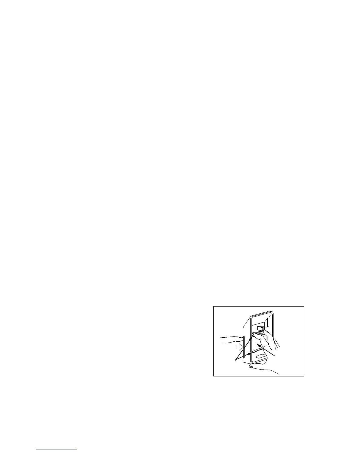
7. Install the retainer assembly into the front cover. Slip the
Lens Support behind the lower retainers, then push in at
the top until the Lens Support snaps into place. Insert the
bug shield and place the lens cover back into the housing.
COMPLETING THE INSTALLATION
Allow at least three minutes for the unit to stabilize after
applying power, during this time the unit will perform its own
self diagnostics and set a baseline detection level. The LED
will flash rapidly for approximately 1 minute and not function
until the unit is ready. If the unit was installed after being kept
in a hot or cold vehicle allow the unit to operate with its cover
in place for about 15 minutes. This will insure that the unit
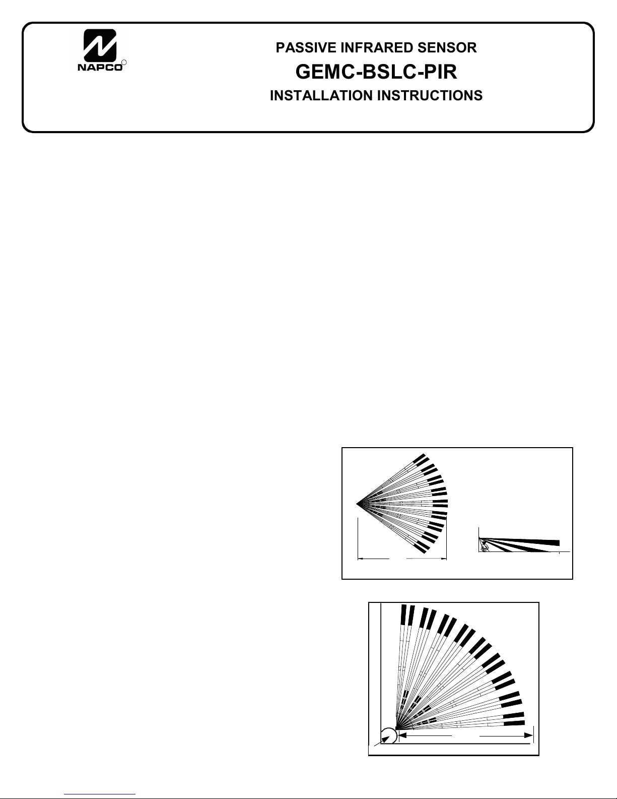
has measured the proper room temperature. Walk test the
unit to insure the desired coverage, making any board height
adjustments that may be necessary. Note: One common
cause of short range is having the lens in upside down--
always check this! During walk test, the unit will go into a
zone-finding mode for 15 seconds after each trip; this will
cause the LED to light each time a beam is entered. To view
the normal detection pattern, remain motionless for at least 15
seconds between walk tests.
NAPCO SECURITY SYSTEMS, INC. (NAPCO) warrants its products to be free from
manufacturing defects in materials and workmanship for thirty-six months following the date of
manufacture. NAPCO will, within said period, at its option, repair or replace any product failing
to operate correctly without charge to the original purchaser or user.
This warranty shall not apply to any equipment, or any part thereof, which has been repaired
by others, improperly installed, improperly used, abused, altered, damaged, subjected to acts
of God, or on which any serial numbers have been altered, defaced or removed. Seller will
not be responsible for any dismantling or reinstallation charges.
THERE ARE NO WARRANTIES, EXPRESS OR IMPLIED, WHICH EXTEND BEYOND
THE DESCRIPTION ON THE FACE HEREOF. THERE IS NO EXPRESS OR IMPLIED
WARRANTY OF MERCHANT ABILITY OR A WARRANTY OF FITNESS FOR A
PARTICULAR PURPOSE. ADDITIONALLY, THIS WARRANTY IS IN LIEU OF ALL OTHER
OBLIGATIONS OR LIABILITIES ON THE PART OF NAPCO.
Any action for breach of warranty, including but not limited to any implied warranty of
merchant ability, must be brought within the six months following the end of the warranty
period.
IN NO CASE SHALL NAPCO BE LIABLE TO ANYONE FOR ANY CONSEQUENTIAL OR
INCIDENTAL DAMAGES FOR BREACH OF THIS OR ANY OTHER WARRANTY,
EXPRESS OR IMPLIED, EVEN IF THE LOSS OR DAMAGE IS CAUSED BY THE
SELLER'S OWN NEGLIGENCE OR FAULT.
In case of defect, contact the security professional who installed and maintains your security
system. In order to exercise the warranty, the product must be returned by the security
professional, shipping costs prepaid and insured to NAPCO. After repair or replacement,
NAPCO assumes the cost of returning products under warranty. NAPCO shall have no
obligation under this warranty, or otherwise, if the product has been repaired by others,
improperly installed, improperly used, abused, altered, damaged, subjected to accident,
nuisance, flood, fire or acts of God, or on which any serial numbers have been altered,
defaced or removed. NAPCO will not be responsible for any dismantling, reassembly or
reinstallation charges.
This warranty contains the entire warranty. It is the sole warranty and any prior agreements or
representations, whether oral or written, are either merged herein or are expressly canceled.
NAPCO neither assumes, nor authorizes any other person purporting to act on its behalf to
modify, to change, or to assume for it, any other warranty or liability concerning its products.
In no event shall NAPCO be liable for an amount in excess of NAPCO's original selling price
of the product, for any loss or damage, whether direct, indirect, incidental, consequential, or
otherwise arising out of any failure of the product. Seller's warranty, as herein above set forth,
shall not be enlarged, diminished or affected by and no obligation or liability shall arise or
grow out of Seller's rendering of technical advice or service in connection with Buyer's order
of the goods furnished thereunder.
NAPCO RECOMMENDS THAT THE ENTIRE SYSTEM BE COMPLETELY TESTED
WEEKLY.
Warning: Despite frequent testing, and due to, but not limited to, any or all of the following;
criminal tampering, electrical or communications disruption, it is possible for the system to fail
to perform as expected. NAPCO does not represent that the product/system may not be
compromised or circumvented; or that the product or system will prevent any personal injury
or property loss by burglary, robbery, fire or otherwise; nor that the product or system will in all
cases provide adequate warning or protection. A properly installed and maintained alarm may
only reduce risk of burglary, robbery, fire or otherwise but it is not insurance or a guarantee
that these events will not occur. CONSEQUENTLY, SELLER SHALL HAVE NO LIABILITY
FOR ANY PERSONAL INJURY, PROPERTY DAMAGE, OR OTHER LOSS BASED ON A
CLAIM THE PRODUCT FAILED TO GIVE WARNING. Therefore, the installer should in turn
advise the consumer to take any and all precautions for his or her safety including, but not
limited to, fleeing the premises and calling police or fire department, in order to mitigate the
possibilities of harm and/or damage.
NAPCO is not an insurer of either the property or safety of the user's family or employees,
and limits its liability for any loss or damage including incidental or consequential damages to
NAPCO's original selling price of the product regardless of the cause of such loss or damage.
Some states do not allow limitations on how long an implied warranty lasts or do not allow the
exclusion or limitation of incidental or consequential damages, or differentiate in their
treatment of limitations of liability for ordinary or gross negligence, so the above limitations or
exclusions may not apply to you. This Warranty gives you specific legal rights and you may
also have other rights which vary from state to state.
NAPCO SECURITY LIMITED WARRANTY
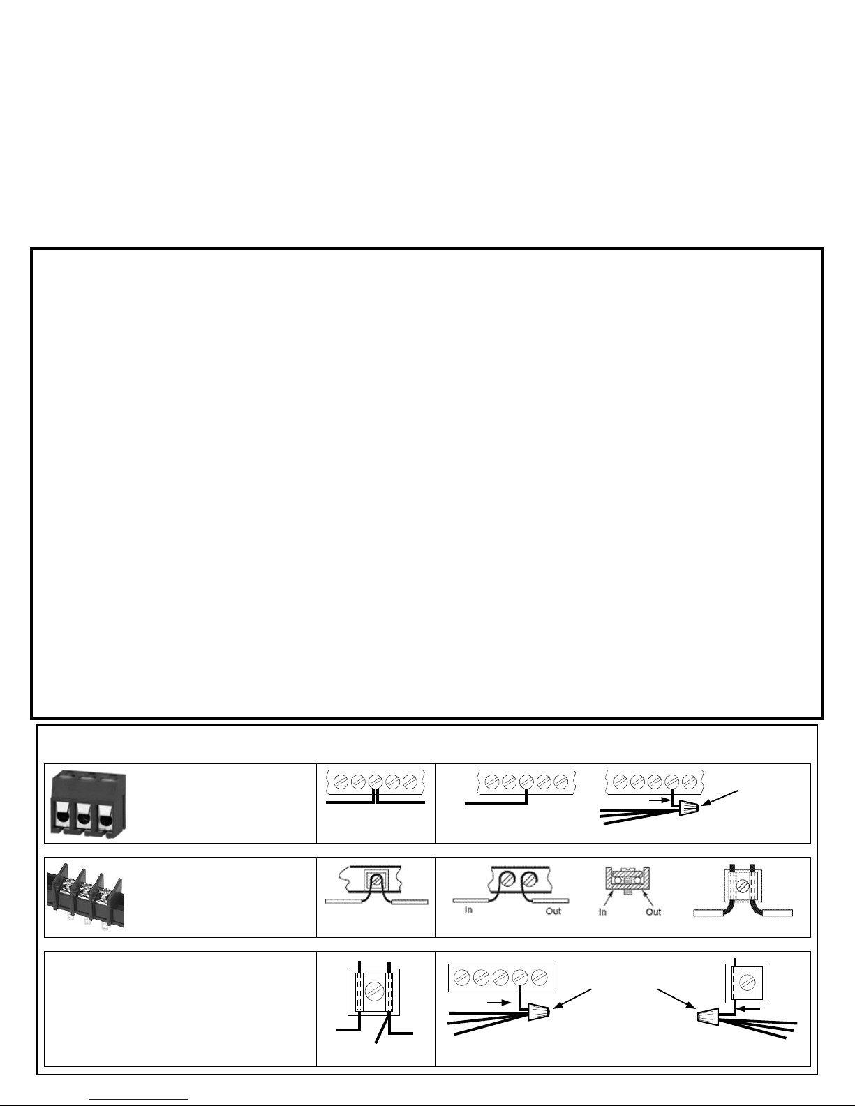
To terminate more than two conductors or
conductors of different wire sizes to a terminal,
use the "pigtail" type wiring method as shown at
right. Use insulated wire for the pigtail, and firmly
secure the conductors to the pigtail using an ap-
propriate wire nut or crimp connector for the num-
ber and gauge of conductors used.
IMPORTANT WIRING METHODS
Incorrect
Correct -- Use pigtail and wire nut / crimp connector
PIGTAIL
WIRE NUT OR
CRIMP
CONNECTOR
PIGTAIL
For single-conductor terminal
blocks (like the type shown at
left), to terminate more than one
conductor to a terminal, use the
wiring methods shown at right:
WIRE NUT OR
CRIMP
CONNECTOR
PIGTAIL
Correct -- Single incoming and/or pigtail with wire nut / crimp connectors
In
For "barrier" type terminal
blocks (like the type shown at
left), to terminate two conductors
to a terminal, use the wiring meth-
ods shown at right: Correct -- Separate incoming and outgoing conductors
In Out
Incorrect
Incorrect
In Out
Table of contents
Other NAPCO Accessories manuals

NAPCO
NAPCO PIR600 User manual

NAPCO
NAPCO GEM-ACM1D User manual

NAPCO
NAPCO Veri-Phone User manual

NAPCO
NAPCO CF5530 User manual

NAPCO
NAPCO GEM-ACM1D User manual

NAPCO
NAPCO PIR1710 User manual

NAPCO
NAPCO SVLBKT User manual

NAPCO
NAPCO DUAL TECH GEMC-BSLC-DT-L User manual

NAPCO
NAPCO IQ PROFILER - User manual

NAPCO
NAPCO GEM-X10 User manual