NAPCO Certa-Set User manual

Certa-Set®
Field Installation Guide

napcopipe.com
1
LATERAL PIPE ASSEMBLY & PREPARATION
Certa-Set 3" Lateral Pipe Assembly
General Notes:
• Certa-Set pipe is intended for pressure pipe applications
involving irrigation water systems. Please refer to the
Field Layout Best Practices for field options and
potential irrigation ideas.
• For instructions regarding pipe handling and additional
installation information, please visit napcopipe.com.
Lubricant Applying lubricantProperly installed O-ring
Applying lubricantLubricant
Notes:
1. Avoid getting lubricant in the spline grooves.
2. Do not use excess lubricant.
O-ring missing O-ring misaligned O-ring properly installedO-ring in spline grove
1. Install an O-Ring in the back groove of each female
end of the sled coupling.
Note: The front groove is the spline groove.
2. Apply lubrication to the O-ring on one side of the sled coupling.
3. Lubricate the spigot end of the pipe.

napcopipe.com 2
Notes:
1. Avoid getting lubricant in the spline grooves.
2. Do not use excess lubricant.
4. Press the sled coupling onto the spigot end of the pipe until the pipe has seated over the O-ring. The spline hole will align
with the groove in the pipe when properly installed.
5. Insert a spline at a low angle to the pipe until the insertion mark (raised dot) reaches the spline hole on the sled coupling.
6. Sprinkler risers:
¾" Pre-assembled Certa-Set Riser or ½" Aluminum Assembled Riser
A. ¾" Pre-assembled Certa-Set Risers
1. Insert the flanged O-ring into the riser. The larger ridge faces the riser cap; the smaller ridge faces the sled
coupling. Do not use lubricant.
Misaligned pipe and
sled coupling
Properly aligned pipe and
sled coupling
Push sled coupling
onto pipe
Push sled coupling
onto pipe
Insert pointed end of
spline first
Push spline into spline hole Spline fully insertedPush spline into spline hole
Missing O-ring Incorrect O-ring
positioning
Correct O-ring
positioning
Correct O-ring
positioning

napcopipe.com
3
2. After inserting the O-ring, screw the assembled riser onto the sled coupling by hand (clockwise). Hand tighten
until it is seated. No tools are required. Do not overtighten.
3. Once riser and sled coupling are assembled, attach the sprinkler to the sprinkler end of the riser.
B. ½" Aluminum Assembled Riser (manufactured by others)
1. The ½ riser consists of the following pieces: A ½" riser cap, chevron gasket and ½" assembled riser.
Note: NAPCO does not manufacture or warranty ½" risers beyond the riser cap.
Position riser to align with
sled coupling
Hand tighten No tools requiredHand tighten
Place [MRDC] [MR] or [MDC]
onto riser first
Hand tighten Place sprinkler head onto
[MRDC] [MR] or [MDC];
hand tighten
Place [MRDC] [MR] or
[MDC] onto riser first
Sprinkler head installed Do not install sprinkler head
with [MRDC] [MR] or [MDC]
Components to field
assemble ½" riser

napcopipe.com 4
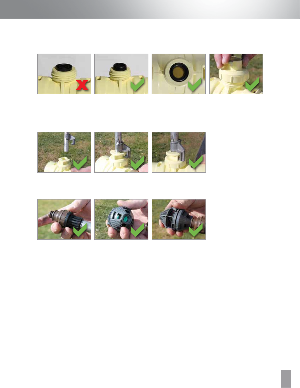
2. Insert chevron gasket into sled coupling “open side down” without lubricant. Screw ½" riser cap (clockwise) until
it is hand tight and seated.
3. Insert ½" riser and turn until the hook is engaged against the stop. Hand tighten until it is seated. No tools are
required. Do not overtighten.
4. Once riser and coupling are assembled, attach the sprinkler to the sprinkler end of the riser.
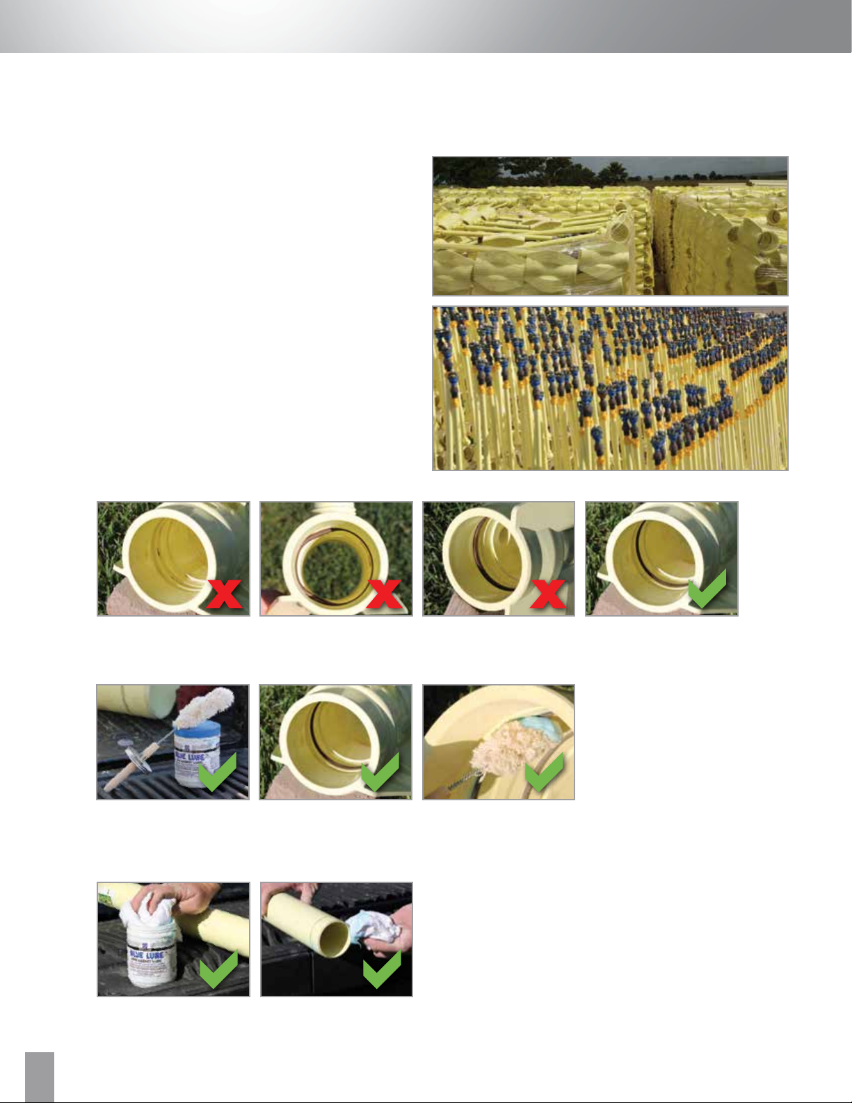
In-correct gasket positioning Align gasket with the sled
coupling before inserting the
gasket into the top opening
Hand tighten riser capCorrect gasket positioning
Align riser with riser cap Hook engaged with stopRotate riser
Place [MRDC] [MR] or [MDC]
onto riser first
Place sprinkler head onto
[MRDC] [MR] or [MDC]; hand
tighten
Place [MRDC] [MR] or [MDC]
onto riser first
Notes:
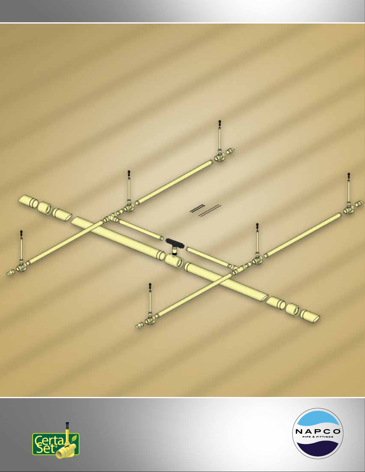
1. Splines should be inserted the same direction to facilitate the removal of the splines when the pipe is removed from
the field with the automatic pipe removal system. Please refer to the Field Layout Planning Guide and the Lateral
Field Installation sections.
2. All 1/2" riser stubs below the quick disconnect hook must be a minimum of 2.25" in length to ensure full
engagement of the coupling boss for proper riser support. Riser OD shaft specification 0.840 +/- 0.010". Maximum
height for the riser is 36 inches when used with rotator sprinklers and 24 inches when used with impact sprinklers.
When using a riser that is higher than the stated dimensions, it is recommended that stakes be utilized to stabilize
the system.
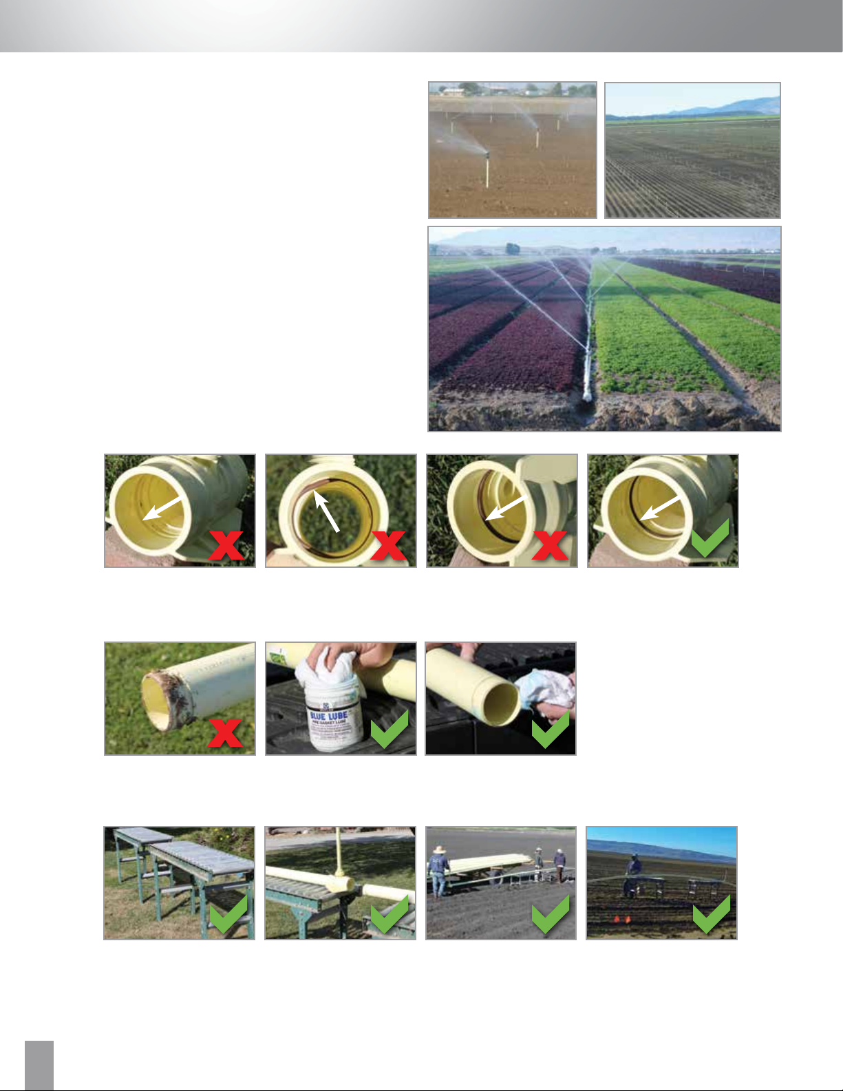
7. Load the assembled 3" Certa-Set piping onto the trailer to transport to the field.
Please refer to the Lateral Field Installation section for additional information.

napcopipe.com
5
LATERAL FIELD INSTALLATION
Field Installation of Certa-Set 3" Lateral Pipe
1. Once Certa-Set Lateral Pipe is assembled and loaded on to
a flatbed trailer, it is ready to transport to the field for final
installation.
2. Before the pipe is removed from the flatbed trailer, inspect
the sled couplings to ensure that the O-ring is inserted
correctly and lubricate the O-ring in the female end of each
sled coupling.
3. While the pipe is still on the flatbed trailer, verify the male end of the pipe is clean and lubricated.
4. Place roller tables in line with intended furrow. Note: The use of roller tables is preferred, but not required.
Notes:
1. Avoid getting lubricant
in the spline grooves.
2. Do not use excess lubricant.
Pipe roller table setup Pipe roller table setup Pipe roller table setup Pipe roller table setup
Unclean pipe Lubricant Applying lubricant
O-ring missing O-ring misaligned O-ring in spline groove O-ring properly installed

napcopipe.com 6
5. Connect the Certa-Set 3" lateral pipe to the tractor via a pulling connection.
6. Remove pipe from flatbed trailer and insert the assembled lateral pipe into the female end of the sled coupling.
7. Insert the spline into the into the sled coupling. Note the importance of spline direction as it relates to pipe removal.
Connecting to tractor hitch #1 Connecting to tractor hitch #2 Final connection Final connection
Final connection
(another option)
Final connection
(another option)
Connecting pipe
to tractor
Connecting pipe
to tractor
Insert pipe into sled
coupling
Insert pipe into sled
coupling
Insert pipe into sled
coupling
Correctly inserted splines
Insert pointed end of
spline first
Push spline into the
spline hole
Spline not inserted in same
direction
Spline not fully inserted

napcopipe.com
7
8. Repeat steps 6 and 7 continuously while the tractor pulls the pipe into the field until the desired lateral length is complete.
Adjust tractor speed to match the speed of pipe assembly.
9. Connect lateral line to the rest of the system. (See the Field Layout and Main Line Pipe Assembly and Installation sections).
10. Flush lateral lines and install the end plugs.
Flush lateral pipe End plug Install end plug
Certa-Set pipe entirely installed
in an “H” design pattern
Certa-Set pipe entirely installed
in the field
Certa-Set pipe entirely installed
in a “U” design pattern
Certa-Set pipe installed
in the field

napcopipe.com 8
CERTA-SET CLIC SPLINE REMOVAL AND INSERTION
To remove the Certa-Set CLIC spline from the Certa-Set CLIC sled coupling:
1. With the end of the coupling facing toward you, begin to gently pull upward and clockwise on the CLIC spline tab until the spline
begins to feed through the spline hole in the coupling.
2. Continue to feed the spline through the spline hole. It may be necessary to manipulate the orientation of the spline in order to
fully remove the spline through the spline hole. Avoid bending the spline excessively during removal.
To Insert the Certa-Set CLIC spline into the Certa-Set CLIC sled coupling:
1. Begin by holding the spline upside down above the top of the coupling with the white stripe facing outward away from the center
of the coupling.
2. Feed the flared end of the spline into the spline hole, ensuring that the end of the spline contacts the coupling in the spline
groove on the coupling ID.
3. Continue to feed the spline counter clockwise through the spline hole and into the coupling.
4. Once the spline is fully fed into the coupling, it may be necessary to adjust the position of the flared end of the spline so that it
catches the lip of the spline hole and creates the springing action when the spline tab is released from the expanded position.
5. When the Certa-Set CLIC spline is correctly inserted, you should be able to see the white stripe on the spline when looking into
the coupling.

napcopipe.com
9
General Notes:
•Certa-Set main line pipe is intended for pressure pipe
applications involving irrigation systems. Please refer to
the Field Layout Planning Guide for field options and
potential irrigation ideas.
• For instructions regarding pipe handling and additional
installation information, please visit napcopipe.com.
1. Inspect the female end of the coupling or tapped coupling, ensuring the O-Ring is properly seated in the rear groove and that
the spline groove (front) is clean and free of dirt and debris.
2. Lubricate the O-ring
Notes:
1. Avoid getting lubricant in the spline grooves.
2. Do not use excess lubricant.
O-ring missing O-ring in spline groove O-ring properly installedO-ring misaligned
Lubricant Applying lubricant Avoid lubricant in
spline groove
Applying lubricant
MAIN LINE PIPE ASSEMBLY & INSTALLATION
Certa-Set Main Line Pipe Assembly & Installation

napcopipe.com 10
3. Lubricate the spigot end of the pipe. Make sure it is clean and free of debris.
4. Start at one end of the pipeline and assemble the pipe against a firm stop, such as lumber or a tractor tire.
5. If installing over a shallow V-ditch, ensure that sufficient lumber for cribbing (raising the pipe above the floor of the V-ditch) is
available. At minimum, a 4" x 4" block in good condition should be used.
6. Insert spigot end of pipe into coupling. Pipe and coupling must be aligned in order for pipe to seat properly against the O-Ring.
Pipe should slide straight into the coupling without deflection.
Pipe with debris Lubricate spigotLubricate spigot
BackhoeTractor tire
Misaligned pipe and
coupling
Properly aligned pipe
and coupling
Notes:
Always push on a coupling surface
and NOT on the end of a pipe

napcopipe.com
11
Main line size Spline length Approximate length
of spline extending out
6" 24" 1"
8" 32" 2 ¼"
10" Two ½ Splines 20" each 1 ½"
12" Two ½ Splines 24" each 2 ¼"
Spline hole(s) Insert pointed end of
spline first
Push spline into the
spline hole
Push spline into the
spline hole
Push spline into the
spline hole
Splines fully inserted
Notes:
If digging bars are used for leverage, protect the pipe with at minimum, a 2" x 4" block in good condition.
Never “hammer” on pipe that does not seat. Check alignment, then apply pressure with a digging bar again. In difficult situations where pipe is
properly lubricated and aligned, use one digging bar to maintain pressure and a second bar to apply additional pressure.
In most cases, when pipe is properly seated, you will feel/hear a slight pop. If the spline will not easily insert into the hole, then the pipe has not
been seated properly.
Bar and block Bar and block StrapBackhoe with a strap
7. Insert each spline(s) into the spline hole until there is a “tail” of the specified dimension below.
8. Repeat as necessary.

napcopipe.com 12
9. Install valve at tapped coupling.
Notes:
1. The Certa-Set main line piping and couplings can be disassembled and reused. See Main Line
Disassembly.
2. Tapped couplings can be easily stripped if threads are not aligned properly. Take precautionary steps to
prevent cross threading.
Best Practices:
Turn the pipe backward so the female end drops in, then tighten. This eliminates stripped threads.
Tapped coupling Threaded adapter Nelson valveTapped coupling
assembly
Nelson valve installed onto
tapped coupling
Secure Nelson valve
installed onto tapped
coupling with spline
Nelson valve

napcopipe.com
13
Typically, the pipe is removed from the field using an AIM
Pipe Retriever. There are two models, the Valley Machine and
the Salinas Machine.
Alternately, some growers choose to pull the pipe in full
lengths into adjacent fields for use or storage.
Field Removal of Certa-Set using the AIM Pipe Retriever
1. Survey field conditions and decide on retrieval direction.
Considerations should be taken for pipeline length, spline
direction and work area limitations (roads, headland
sizes, ditches)
2. Disconnect pipe from the main line connection. Remove
swing joints (19 foot 3" Certa-Set lateral) and transition
fittings. Note: the transition fitting (Tee or elbow) should
be at 90 degrees so that the outlet is facing up.
LATERAL PIPE FIELD REMOVAL
Certa-Set Lateral Pipe Field Removal Guide
Swing joints are on both
sides of the Nelson valve
Nelson valve with burried
main line
Elbows connecting
lateral pipe runs
Tees
End plug to be removed Remove spline Remove end plug Drain piping
3. Follow all operating procedures and safety precautions as instructed by the pipe retriever manufacturer. The illustrations
and notes below are general guidelines, and all safety and operating requirements from the pipe retriever manufacturer
and Occupational Safety and Health Administration (OSHA) shall take precedence.
4. Disconnect 3" Certa-Set end plugs and drain line completely. Failure to drain lines will result in damage to the pipe
and will void the warranty.

napcopipe.com 14
5. Prior to using the AIM Machine, pull each pipeline with a tractor and strap to break it free from any accumulated silt and
entwined foliage.
6. Drive the AIM Pipe Retriever into position parallel with the head of the field. Using a spotter, align both ramps of the machine
with the pipeline, ensuring almost perfect alignment across the machine.
7. Place an extra section of pipe in the AIM Machine and CLOSE the drive wheels.
8. Connect the pipe in the machine to the first coupling of the pipeline.
Silt and foliage surrounding
sled coupling
Connecting to tractor to
break pipe free for removal

napcopipe.com
15
9. Begin pulling the pipe with BOTH DRIVE LEVERS pointing to the outboard direction.
10. When the first sled coupling reaches the center of the machine, bump the outboard drive lever inboard to relieve the tensile
pressure off of the coupling. The machine operator will then remove the spline and place it in a bucket.
11. Pull the outboard lever to the outboard direction first, separating the pipe from the coupling.
12. Repeat Steps 8-10 until the entire pipeline is removed. Leave the last piece of pipe in the machine to facilitate the
connection to the next lateral pipe run to be removed.
13. Repeat steps 7-11 until the pipe is clear of the field.

napcopipe.com 16
Pulling the 3" Certa-Set lateral lines into an adjacent field
1. Survey field conditions and decide on retrieval direction. Considerations should be taken for pipeline length, spline direction and
work area limitations (roads, headland sizes, ditches).
2. Disconnect pipe from the main line connection. Remove swing joints (19 foot 3" Certa-Set lateral pipe) and transition fittings.
3. Disconnect 3" Certa-Set end plugs and drain line completely. Failure to drain lines will result in damage to the pipe
and will void the warranty
4. Connect the pipeline to the tractor using a pulling connection.
5. Slowly pull the pipeline, ensuring that it is not binding up on any obstruction.
6. Tow pipe into place in next field and reconnect as necessary.
Swing joints are on both
sides of the Nelson valve
Nelson valve with
buried main line
Elbows connecting
lateral pipe runs
Tees
End plug to be removed Remove spline Remove end plug Drain piping
Position tractor Connect pipe to
tractor hitch
Insert spline Final connection to tractor to
remove/move pipe

1.855.624.7473 | napcopipe.com
NAPCO
2801 Post Oak Blvd., Suite 600
Houston, TX 77056
©2019 NAPCO, a Westlake company All rights reserved AG-BR-002-US-EN-0819.2