8
W415-0369 / F / 12.10.07
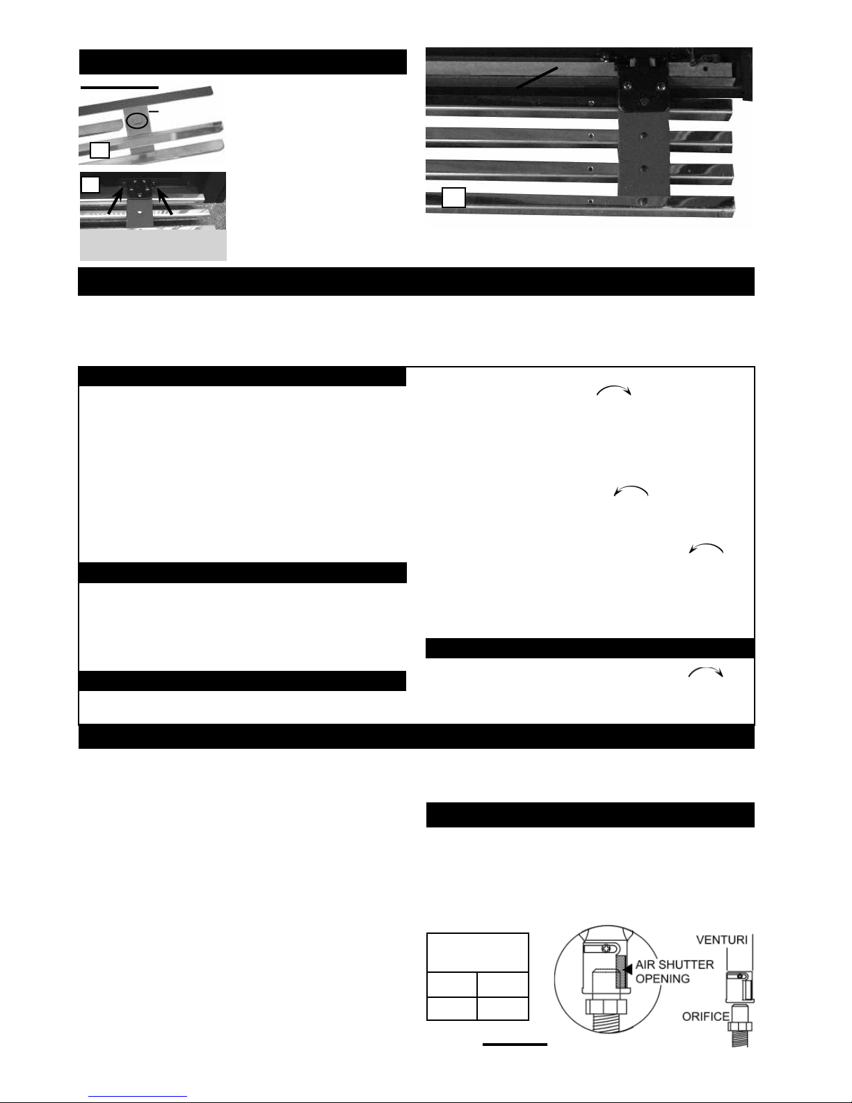
LOUVRE
HOOD
SLOT
BRACKET
A
Do not use steel wool, as it will scratch the finish. Stainless steel parts
will discolour when heated, usually to a golden or brown colour. This
discolouration is normal and will not affect the performance of the ap-
pliance.
Air shutter adjustment must only be done by a qualified gas
installer!
Closing the air shutter will cause a more yellow flame, but can lead to
carboning. Opening the air shutter will cause a more blue flame, but can
cause flame lifting from the burner ports. The flame may not appear yel-
low immediately; allow 15 to 30 minutes for the final flame colour to be
established. Opening the air shutter will also reduce exhaust odours.
See Trouble Shooting Guide.
UPPER LOUVRES: Insert the
upper louvres into the slots on
both brackets. Press the top
flange of the hood into the four
clips located along the top of
the unit as shown.
LOWER LOUVRES: Attach
each hinge to the firebox with
2 screws.
HINGE SCREEN
C
1. Stop! Read the safety information on the operating label.
2. Turn the gas knob clockwise to off.
3. Wait five (5) minutes to clear out any gas. If you smell gas including
near the floor, stop! Follow “b” on the operating label. If you don’t
smell gas go to the next step.
4. If fireplace is equipped with flame adjustment valve turn clock-
wise to off.
5. Find pilot located in front of back log.
6. Turn gas knob counter-clockwise to pilot.
7. Depress and hold gas knob while lighting the pilot with the push
button igniter. Keep knob fully depressed for one minute, then re-
lease. If pilot does not continue to burn repeat steps 3 through 7.
8. With pilot lit, turn gas knob counter-clockwise to
on.
9. If equipped with flame adjustment valve, push and turn knob
to high.
10. If equipped with remote on-off switch, main burner may not come
on when you turn the valve to on or high. Remote switch must be
in the on position to ignite burner.
• Push in gas control knob slightly and turn clockwise to
off. Do not force.
CAUTION: Label all wires prior to disconnection when servicing con-
trols. Wiring errors can cause improper and dangerous operation. Verify
proper operation after servicing. This heater should be inspected and
serviced before use and at least annually by a qualified service person.
The fireplace area must be kept clear and free of combustible materials,
gasoline or other flammable vapours and liquids. The flow of combustion
and ventilation air must not be obstructed.
1. Keep the control compartment, logs, burner, air shutter opening
and the area surrounding the logs clean by vacuuming or brushing, at
least once a year.
2. Check to see that all burner ports are burning. Clean out any of the
ports which may not be burning or are not burning properly.
3. Check to see that the pilot flame is large enough to engulf the ther-
mocouple and thermopile and promptly ignites the main burner.
4. Check to see that the main burner ignites completely on all open-
ings when the gas knob for the burner is turned on. A 5 to 10 second
total light-up period is satisfactory. If ignition takes longer, consult your
NAPOLEON® dealer / distributor.
Cleaning Stainless Steel: Do not use abrasive cleaners to clean any
painted, porcelain or stainless steel parts. To clean stainless surfaces,
use a stainless steel cleaner or a non-abrasive cleaner. Always wipe in
the direction of the grain.
MAINTENANCE
VENTURI ADJUSTMENT
If heater keeps shutting off, have it serviced. Keep burner and control
compartment clean.
When lit for the first time, the fireplace will emit a slight odour
for a few hours. This is a normal temporary condition caused by
the curing of the logs and the “burn-in” of lubricants used in the
manufacturing process and will not occur again.
After extended periods of non-operation, the fireplace may emit
a slight odour for a few hours. This is caused by dust particles
burning off.
OPERATION / MAINTENANCE
• Do not use a mobile or land phone.
• If you cannot reach your gas supplier, call the fire department.
• Turn off all gas to the fireplace.
• Do not try to light any appliance.
• Immediately call your gas supplier from a neighbour’s phone.
Follow the gas supplier’s instructions.
When lighting and re-lighting, the gas knob cannot be turned from
pilot to off unless the knob is depressed.
A. This fireplace is equipped with a pilot which must be lit by hand
while following these instructions exactly.
B. Before operating smell all around the fireplace area for gas and
next to the floor because some gas is heavier than air and will settle
on the floor.
C. Use only your hand to turn the gas control knob / manual shut-off
knob. Never use tools. If the knob will not turn by hand, do not try to
repair it. Call a qualified service technician. Force or attempted repair
may result in a fire or explosion.
D. Do not use this fireplace if any part has been under water. Im-
mediately call a qualified service technician to inspect the fireplace
and replace any part of the control system and any gas control which
has been under water.
FOR YOUR SAFETY READ BEFORE LIGHTING:
WHAT TO DO IF YOU SMELL GAS
LIGHTING INSTRUCTIONS
TO TURN OFF GAS
LOUVRE INSTALLATION
FIGURE 15a-c
NG 3/16”
LP 1/4”
AIR SHUTTER
OPENINGS
LOWER LOUVRES
(VALVE CONTROL DOOR)
B
HINGE SCREEN: Position the hinge screen into place and with the
control door open, secure to the firebox using three screws.
FIGURE 16