Narada FEN4850 User manual

LITHIUM IRON PHOSPHATE BATTERY
NARADA POWER SOURCE CO., LTD
OPERATION MANUAL
Version 1.0
FEN4850
(Outdoor battery for Telecom-5G)

01 02
CONTENTS
03
04
10
12
17
11
Safety and Warning
Product Introduction
Product Features
Main application
Dimension
Layout
Working principle
Technical Characteristic
Discharge performance
Charge performance
Operation
Parameter settings
Operation condition
Storage and Installation
Storage
Installation
Maintenance
General
Troubleshooting and Solutions
Annex1
Annex2
Annex3
Annex4
4
4
5
6
8
10
10
17
18
19
20
21
11
11
12
13
Notes
Two
One
Four
Five
Three
22

Safety and Warning
Chapter Notes
Product Introduction
Chapter One/01
Product Features
The FEN4850 LiFePO4battery system installation, operation, maintenance should follow
important recommendations in this manual:
The equipment shall be installed by the professional trained staff.
Battery maintenance should be carried out by the experienced professionals and aware of the
preventive measures on the potential harm of the battery.
Note: Be care of the risk of electric shock for large current in case of battery short circuit, pay
attention to the following points during operation
Do not direct access to the battery system to the mains grid power outlet.
Do not put the battery system into re, do not use or storage the battery near to the high
temperature source.
Do not use liquid or other objects placed into the battery system.
Do not open or cut the battery, not hit, throw or step on the battery.
Using special communication between battery module and power plant to charge battery
Be sure to subject to charge and discharge parameters setting in this manual.
The output interface of the system is still voltage when grid power cut, avoid electric shock or
short circuit when operation.
Please check if the box is damaged. If damaged, please immediately notify the supplier
If you nd leaking liquid or white powder residue on product, prohibit operation.
03 04
Narada FEN4850 lithium iron phosphate battery is a safe and reliable 5G micro-station backup
power system, which can meet the backup power supply requirements of 5G micro stations,
network equipment, communication equipment, transmission equipment.
The module is able to adapt a variety of 48V communication power system, It has many
characteristics, such as flexible configuration, modular design, IP65 waterproof, outdoor pole
installation, background remote monitoring function and multi-group system parallel communication
function, internal heating system for low temperature use,intelligent battery management
technology with protection functions such as voltage, current and temperature, high energy
density, long life, high charge and discharge rate, etc,.
Main application
■Remove watches, rings or other metal objects
■Use tools with insulated handles
■Do not place tools or metal objects on the battery
Please take care of the following marks
Warning Electricity
danger
Fire
forbidden Circle used
Protecting
your eyes
Watch
Short-circuits
With adults
custody
Do not put
batteries into
dustbin
The product has
passed the UL
authentication
Read the
manual
Outdoor distribution system
Telecom Micro-Station

05 06
Dimension Layout
Fig.1-2 Battery Output Terminal
Table 1-1 Battery Model & Dimension of SFEN4850 Battery
FEN4850 33 310 222 448 ---
Battery
Model①
Typical
Weight
(kg)
Battery Output
Terminal
Dimensions(mm)
Depth Φ
Width
(No ear) Height
Fig. 1-3 Layout of Front Panel for FEN4850 Batteries
(Received product may not have all parts above, this instruction is as an example)
Table 1-2 Instruction for Layout of Front Panel
1
2
Marks
No. Detailed Information
Functions
There is one red LED light in front panel indicating alarms.
Detailed information is shown in Annexed Table 1.2.
There is one green LED light in front panel indicating
running status. Detailed information is shown in Annexed
Table 1.1.
Indicator for
alarms
Indicator for
running status
ALM
RUN
3
4
communication
port
COMM
It is adopting RS485 series port communication pattern
to upload data. Contents of data transmit include
BMS parameters, battery running status, alarms, etc.
Communication of modules connected in parallel is
available through RS485, FEN4850 battery have 2 COMM
for communication. please see Annex 3 for details.
Power
Terminals
Input/
Output
FEN4850 battery has 4 power input and output ports, each
input and output port can input and output power
independently, please see Annex 3 for details.
Fig.1-1 Structural Drawing of FEN4850 Batteries

07 08
It can be used to view battery information through WIFI,
please see Annex 4 for details.
WIFI Module
WIFI
5
The FEN4850 battery can be turned on and off by using
the key switch, and the key can be pulled out and
inserted in the on and off state.
Connect earth by exible cable above GREEN Sheathed,
UL94-V0, gauge of the grounding wire should be equal to
or greater than the gauge of the battery return wire.
Ground screw
Pressure relief
valve
Key Switch
Safety
valve
Power
Switch
GND
6
8
7
Working Principle
The FEN4850 battery system mainly includes Lithium battery pack, battery protection, cell
balancing unit, monitoring module and charge-discharge management module for optional. Its
schematic diagram shown in Figure 1-4
Fig. 1-4 Schematic Diagram
LFP cells
Cell protection
Cell balancing
Monitoring
Chemical power, energy storage and power supply components.
Protect LFP cells against overcharge, over discharge, over current, over
temperature, short circuit
Equalization LFP cells for cells unbalanced
Support centralized monitoring system (optional according to customer
requirements)
FEN4850 battery working principle:
DC power input rectier after lter, DC divided two circuits, one circuit directly supply the load, another
circuit charge lithium battery. When grid power on, the system supplies the loads and charging inside
lithium batteries; When grid power failure, lithium inside system supply DC power to the load, to
ensure uninterrupted power supply as power system.
Battery Management System (BMS)
Smart BMS technology is adopted for battery modules of FEN4850 battery to assure smart
automatic management for batteries. Features of BMS are shown as below:
In case of safety problems, the pressure relief valve
can release the pressure inside the battery in time to
ensure the safety of the battery.

09 10
There is a centralized monitoring unit in BMS. Functions such as remote measurement, remote
communication, remote controlling are available. Battery modules can be controlled
remotely by staffs in control center. FEN4850 battery are in line with the requirements of the
development of modern communications technology.
It is combined by technologies of power source and computer. Parameters and status of rectiers
and AC/DC distributions can be detected and controlled.
Excellent electromagnetic compatibility. BMS used for battery modules of FEN4850 battery
can comply with the outdoor power plants during operation, no interfere with each other.
BMS can provide protections against overcharge, over-discharge, over-temperature, over current,
short circuit, etc., to assure reliable safety and operation life.
With patented cell balancing technology, BMS provide high efciency f or c ell b alancing and
prolong system operate life.
Conguration exibility, support parallel connection expansion
Technical Characteristic
Chapter Two/02
Discharge performance
Fig.2-1 Discharge curve at different constant current of FEN4850 battery
Charge performance
Fig.2-2 Charge curve at different current limitation of FEN4850 battery
54.5
40.5

11 12
Operation
Chapter Three/03
Parameter settings
Lead-acid batteries can be replaced by lithium battery of FEN4850 battery if power is matched.
Table 3-1 is new parameter settings of power plant for lithium battery.
Table 3-1 Parameter Settings of Power Plant for FEN4850 Batteries
1
2
3
4
5
6
7
8
9
10
11
12
13
Float charge voltage
Equalization charge voltage
Standard charge current
Charge current limitation
Equalization charge interval
Equalization charge duration
Condition to equalization charge
Condition to oat charge
Recovered LLVD voltage
LLVD
BLVD
Temperature compensation for oat charge
Temperature compensation for equalization charge
V
V
A
A
day
H
A
A
V
V
V
-mV/°C
-mV/°C
54.0
NA or 54.1
0.2C
0.5C ~ 1.0C
NA
NA
NA
0.05C
50.0
47.0
43.2
NA
NA
Parameters
No. Defaults
Units
Note:
1.Equalization charge is requested to switch off for FEN4850 batteries.
2.Rectifier parameter shall be set according to specific site requirement based on battery units used.
3.If the battery connected more than 2 in parallel, the max. charge current recommend 0.5C.
Operation Condition
Table 3-2 Requirements for Operation Environment
Temperature
Range (°C)
Discharge
Charge
Storage
Discharge
Charge
Storage
-40 ~ +60
-40 ~ +60
0 ~ +40
+15 ~ + 35
+15 ~ + 35
+15 ~ + 30
5% ~ 95%
Recommended
Temperature(°C)
Humidity
Storage
Storage and Installation
Chapter Four/04
■Storage temperature range: 0°C to 40°C.
■Storage battery should be at 50%-80%SOC.
■Recharge charge before using to recover capacity loss of self-discharge during storage and
transport.
■Recharge battery during long-term storage for self-discharge. Recharge program as follow table:
■Storage battery over 40°C or under 0°C will reduce battery life,
■Storage battery in dry and low temperature, well ventilated place
■Battery performance degradation after long-term storage, please shorten shelf time as possible
as you can.
■When the battery is stored and transported, the battery should be placed strictly in the
following:
Every 6 months
Every 3 months
0°C-30°C
30°C-40°C
1) Charge with 0.2C to 100%SOC
2) Discharge with 0.2C to 0%SOC
3) Charge with 0.2C per module for 4 hours
Single Module Recharge ProcedureRecharge intervalStorage temperature
Normal Forbidden
ForbiddenForbidden

13 14
Installation of Battery Modules
1.Installation of mounting bracket
Mounting the mounting bracket of fen4850 battery on the pole.
Note:
Because customers have different requirements for mounting brackets, Narada does not provide
mounting brackets for the time being. It is configured by the customer, but the mounting holes of
the mounting brackets need to match the mounting holes of the FEN4850 battery.
If the mounting bracket must be provided by Narada, the customer needs to provide Narada with a
drawing of the mounting bracket.
2.Installation the handle and corner guard
Install the handle and corner protector on the battery with the mounting bolt provided by Narada. In
order to facilitate the transportation of the battery, and protect the battery terminal from being
damaged when the battery is dropped, causing a short circuit and causing danger.
Installation
Unboxing & Inspection
■Please study this manual before installation.
■Please inspect the package before unboxing, if any destroy with appearance, contact with the
supplier as soon as possible.
■This device shall be installed and operated by professionals.
Preparation for Installation
■Batteries shall not be placed close to heat source.
■Batteries shall be installed in place with good ventilation to assure enough heat dissipation.
■Batteries shall be placed in are with clean ambient and low humidity.
■Heavy weight shall not be placed on any cable.
■Following are the tools possibly but not limited be use for installation:
3.Installation the battery
Install and fix the battery on the mounting bracket.
M6
M5
Note:
1. Due to the heavy weight of the battery, safety protection should be taken during installation to
avoid personal injury when the battery accidentally falls.
2. The installation must be tight, and the battery port must face the ground.
3. Although the FEN4850 battery has an IP65 protection level and has a lightning protection
configuration, it is still necessary to take protective measures such as lightning protection for the
installation pole.
4. FEN4850 battery can be installed in two ways: back mounting and side mounting
(Depth: 10mm)
Mounting holes:
Mounting
Bracket
Hole
Side
Mounting
Back
Mounting

15 16
7.Power on for battery module
■When installation is accomplished, battery module is in dormant state. Take on of the Key Switch,
battery will go into normal running status, and discharge/charge can be available.
■Parameter settings for lithium battery modules in power plant are shown in Table 3-1.
■After the battery is turned on, you need to pull out the key and close the key switch protective
cover to ensure that the IP protection level of the battery is IP65, and keep the key properly to
avoid the loss of the key and the battery cannot be turned off and on.
5.RS485 communication connection
■Connect the battery to the device/PC through the communication cable provided by Narada. The
cable has an anti-misconnection setting.
■If there is only one battery module in operation, communication between battery module and
computer can available through RS485.
■If there are more than one battery modules in operation, parallel communication can be available
using RS485.
■Communication protocols for RS485 are shown in Annex 3.
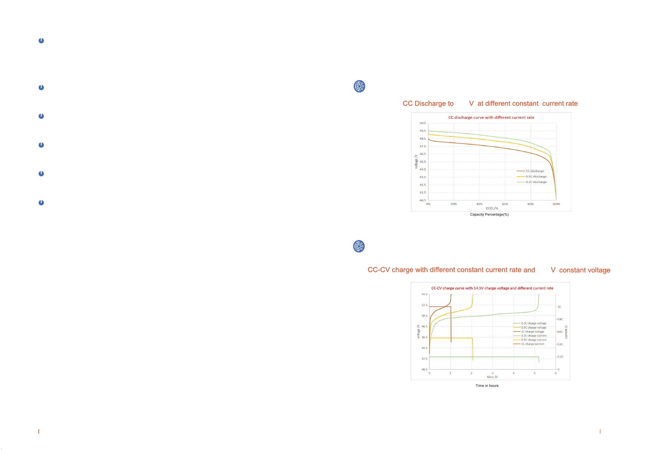
6.Discharge with dummy load
■Dummy load cannot be larger maximum discharge current of FEN4850 battery according to the
datasheet, and BLVD is larger than 43.2V.
■Voltage drop on cable between battery module and power plant shall be less than 0.5V . Method
of calculation for cross sectional area of cable is shown as below.
A=ΣI×L/(K×△U)
In the above formula, A is across sectional area of wire (mm2), ΣI is the total current (A), L is length
of cable, △U is the permit voltage drop on cable (V), and K is electrical conductivity of wire. For
example, for copper, K = 57.
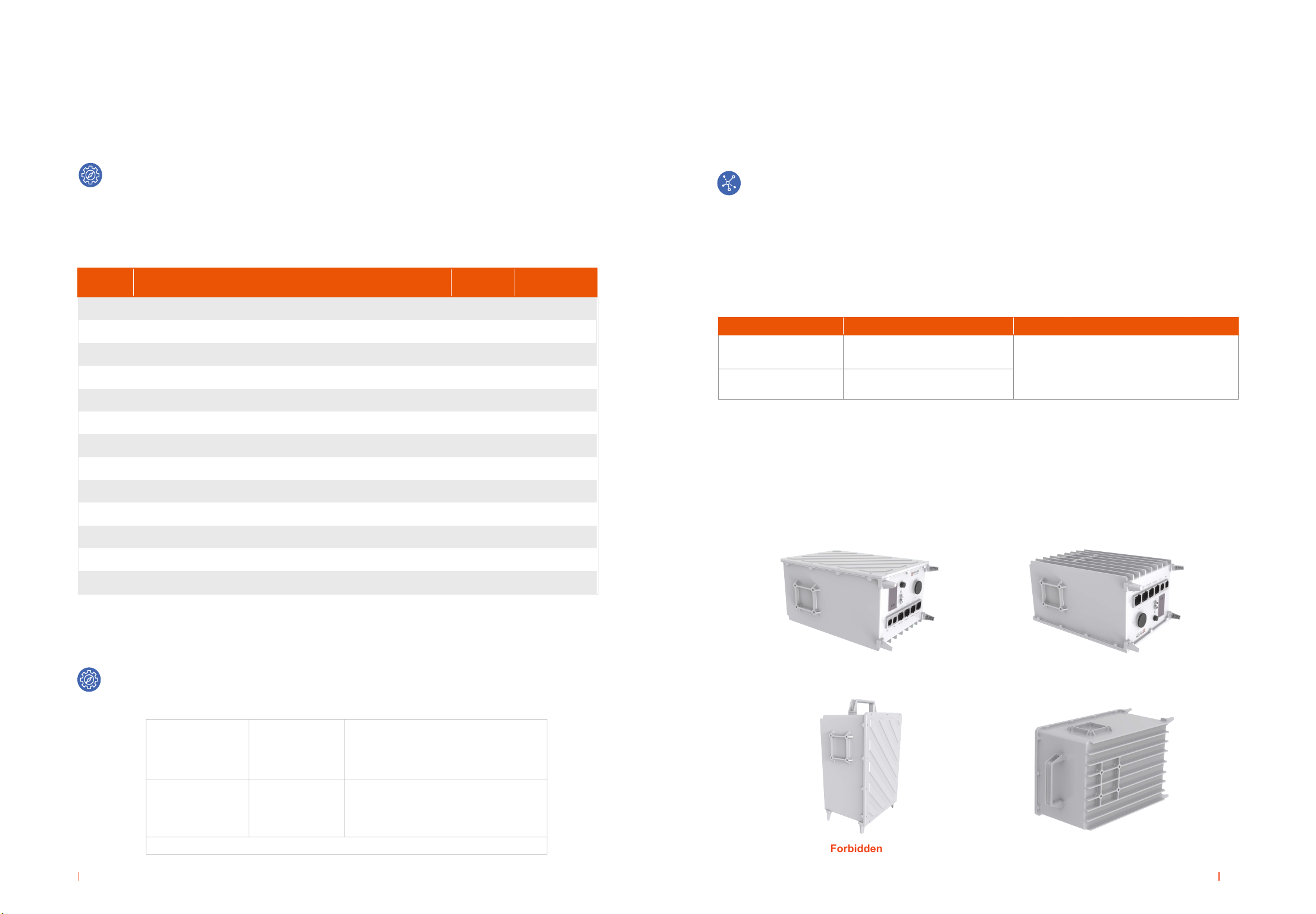
6.Battery output connection
■Connect the battery and the device busbar through the power cable provided by Narada, and the
cable has an anti-misconnection setting.
■The red of the power cable is the positive, and the black is the negative.(See Annex 3)
■If multi battery modules will be connected in parallel, please take note of follows:
1)
The battery modules connected no more than 8 in parallel.
2)
Connect ‘+’ of battery output of each battery module with positive copper bar of power
plant,and ‘-’ with negative copper bar of power plant or power switch separately.
3)
Length of cable between battery module and power plant shall be less than 2.0m. To make
sure similar voltage drop of cable for each battery, length of all positive and negative cables
should be the same.
4.Ground connection
Connect earth by flexible cable above GREEN Sheathed, UL94-V0, gauge of the grounding wire
should be equal to or greater than the gauge of the battery return wire, .no less than 6AWG,
The FEN4850 battery has 2 grounding bolts (M6).

17 18
Maintenance
Chapter Five/05
General
■The battery shall be recharged every three months if in long time storage
■Please use clean and dry cloth/fabric to clean up the cabinet, if need further cleaning, please use
neutral cleanser. Alcohol or ammonia synthesis is forbidden.
■Carrying shall be handled gently, prevent from severe compact
■Prevent battery from splashing liquid
■Suggest inspect the tighten of output screw every years
Troubleshooting and Solutions
Battery cannot
discharge
Battery cannot
charge
All LED indicators
on
Communication
failure
Protection against under-voltage
Protection against over-temperature or under-
temperature (cell temperature is lower than
-30°C or higher than 70°C)
Battery output is short circuit
Protection against over current
System failure
Battery is fully charged. Normal charge
management
Protection against over voltage
Protection against over-temperature or under-
temperature (cell temperature is lower than -0°C
or higher than 65°C)
System failure
System failure
Fault of communication cable
Halt of System communication management
System failure
Charge battery
Regulate cell temperature in
the range of -20°C to 65°C for
discharge
Relieve short circuit and charge
battery
Remove some unimportant load
and charge battery
Shutdown system and call
maintenance service
Do not need to solve
Regulate cell temperature in the
range of 0°C to 55°C for charge
Shutdown system and call
maintenance service
Shutdown system
Call for maintenance service
Inspect communication cable
Restart Key Switch
Shutdown system
Call for maintenance service
Troubleshooting
Troubles Solutions
Different ash status of LED indicators represents corresponding running status or alarms. Detailed
information is shown Annex 1.
Note: The improvement of product and technology, and the possible of battery specication and appearance
changes, Narada hold the right of nal explanation!
Table 5-1 Troubleshooting and Solutions
Proper maintenance will prolong the life of a battery and will aid in assuring that it can satisfy its
design requirements. A good battery maintenance program will serve as a valuable aid in determining
the need for battery replacement. The users must consider their application and reliability needs
if maintenance procedures, other than those recommended in this document, are used. Battery
maintenance should be performed by personnel knowledgeable of batteries and the safety
precautions involved.
FEN4850 batteries can be used at an altitude of less than 5000 meters. If the altitude more
than 5000 meters, it will affect the battery performance and life due to the decrease of air
pressure and temperature.

19 20
Annex 1-Instructions for LED Flash
Annex Table 1.1 – RUN Indicators Description
Annex Table 1.2 – ALM Indicators Description
Annex Table 1.3 – Flash Instruction of LED Indicators
Running Status of Battery
Alarm Information of Battery
Flash Status
Flash Status
ON OFF
Flash 1
Flash 2
Continue light
Extinguish
Extinguish
Flash 2
Flash 3
Continue light
Flash 1
Flash 2
Flash 3
0.25s
0.5s
0.5s
3.75s
0.5s
1.5s
Activation state, but neither charge nor discharge
Charging state
Discharging state
Dormant state
Minor Alarm(Various Alarm Status)
Fail(Various fail)
Major Alarm(Various protection status)
Normal, no alarm
Annex 2 – Instructions for Parallel Communication
FEN4850 battery packs are automatic assigned addresses through CAN bus for parallel
communication, and RS485 interface realizes communication with PC or other intelligent
terminals. The bus interface of multiple batteries in parallel is shown in the figure below.
Parallel communication supports 16 batteries maximum.
Flash Status
Instructions for Parallel Communication of FEN4850 battery

21
Annex Table 3.2 – Pin assignment for Power port and cable
Pins Color Denition
Annex 3 – Pin assignment for Communication and Power cable
The pins of power port and communication port of FEN4850 battery are marked, and the Port
has anti-misconnection settings. When the corresponding pin is wrong, the connection line
and terminal cannot be connected. The following is the detailed information of port pin:
Annex Table 3.1 – Pin assignment for Communication port and cable
A-A
B-B
C-C
D-D
------
------
Red
White
Yellow
Black
A
B
C
D
Positive
Negative
Negative
Positive
Red
Black
Black
Red
Annex 4– Introduction of WIFI
FEN4850 battery has WIFI function, you can connect the battery through mobile phone WIFI
and view battery data.(Only supports Android system)
1, Install the WIFI App on the mobile phone, and open the WIFI of the phone.
2, 2SHQWKH$SSDQGFRQQHFWWKHFRUUHVSRQGLQJEDWWHU\:,),, WKHQ\RXFDQFKHFNWKHGDWD
RI EDWWHU\
Pins Color Denition
Pins Color Denition
1-D
2-C
3-D
4-
------
RS485 A(+)
------
Orange & White
Green & White
Orange
Communication Protocol:
Narada Modbus 1. 5 (Can be changed according to customer requirements)
22
5-
6-
7-A
8-B
------
RS485 B(-)
------
Brown & White
Brown
------
------
------
------
------
RS485 A(+)
RS485 B(-)

NARADA POWER SOURCE CO., LTD.
NARADA ASIA PACIFIC PTE. LTD.
NARADA EUROPE (UK) LIMITED
Building A, No.822 Wen'er West Road, Hangzhou, Zhejiang, China
Tel: +86-571-56975980 Fax: +86-571-56975955
Block 9 Khaki Bukit Road 1 #02-10 Eunos Technolink, Singapore 415938
Tel: +65-6848 1191 Fax: +65-6749 3498
Spectrum House, Dunstable Road, Redbourn, St. Albans, Herts Al3 7PR
Tel: +44 (0)845 612 2031 Fax: +44 (0)845 612 2031
E-mail: [email protected]
After-sale Services
MPINARADA – North America
44 Oak Street Newton, MA 02464, U.S.A
Tel: +1800-982-4339 Fax: +1 800-982-4339
E-mail: [email protected] Website: www.mpinarada.com
Table of contents
Other Narada Camera Accessories manuals

Narada
Narada VRLA Series User manual

Narada
Narada MPG Series User manual

Narada
Narada 6V Series User manual

Narada
Narada eco-200 User manual

Narada
Narada ACMEG AG12V50F User manual

Narada
Narada Ares OPzV Series User manual

Narada
Narada NL 3540108H Owner's manual

Narada
Narada 12NDT26 User manual

Narada
Narada NPFC Series User manual