6V&12V Serials
09 10
Charge requirement
Charge requirement NoteCharge mode
More than two battery voltages in the battery
string are lower than 2.18V in oating operation Equalization charge
Equalization charge
Complement charge
Complement charge
Recommend charging if oat charge for
more than three months
Battery storage for more than 6 months
Before the battery is installed
and applied in the site.
After the battery discharged
Charge current:
Limited current I10~2.5I10
Charge voltage:
Limited voltage 2.35V/cell
Charge time:
24 hours
Note:
(1) When the depth of discharge is large (usually more than 5~10% C10), it is recommended to use the equalization voltage,
so that this charge mode is more adequate. When charges for 24 hours or the current drops below 0.005C10A, and the current
value is substantially constant for three consecutive hours, the charge is considered complete.
(2) The battery needs to be fully charged as soon as possible, the charge current can be increased appropriately, but it cannot
be higher than recommend value.
(3) If the battery is not recharged in time after discharge, or the power is off again during recharge, the insufcient-charged
batteries will be frequently discharge, thus the batteries will lose part of capacity in short period. And it may cause capacity
loss at initial stage and the batteries will be rejected if the situation is serious.
Battery recharge method
Step 1: Connect the batteries in series, and ensure that the bolts and screws are fastened.
Step 2: Connect the positive and negative poles of the battery to the positive and negative poles of the charging device.
Step 3: Turn on the charging power supply, set the charging current limit value and charging voltage value according to the
supplementary power requirements;
/<$+"%,4('"()';",(%$("(6$
.8"<%$+'18+$$D=>
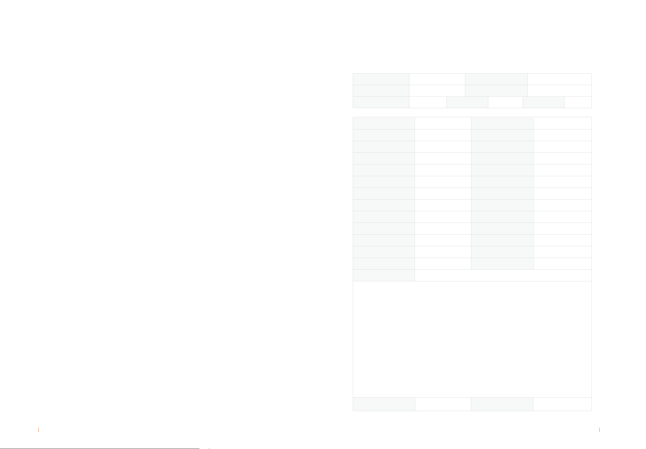
| Parameter settings
Table 3-1 Switching power supply parameter setup table (48V system, 25°C)
54.0
54.4
54.0
54.4
Parameter name Tough power supply
(Cyclic operation)
Normal power supply
(Floating operation)
<5
-5
<5
-5
56.4 56.4
Please refer to table 3-2
55.2
0.1C10
0.25C10
90
24
>50
49
57.6
46
-3
35
45
35
45
50
57.6
47
-3
55.2
0.2C10
0.25C10
30
24
>50
Acme, AcmeG, MP, MPG, GP, GPG,
12REXC, ICS, UDS, DT
HRL, HTB,HTB-F
Acme, AcmeG, MP, MPG, GP, GPG,
12REXC, ICS, UDS, DT
HRL, HTB,HTB-F
12REXC
Charging Current(A)
Limited Current For Charge (A)
Equalization Charge Cycle(day)
Equalization Charge Time(h)
LLVD (V)
BLVD (V)
BLVD Recover Voltage(V)
High Voltage Warning(V)
Low Voltage Warning(V)
Condition to Change Float Charge To
Equalization Charge(mA/Ah)
Acme, AcmeG, MP, MPG, GP, GPG,
ICS, UDS, DT, HRL, HTB,HTB-F
Condition To Change Equalization
Charge To Float Charge(mA/Ah)
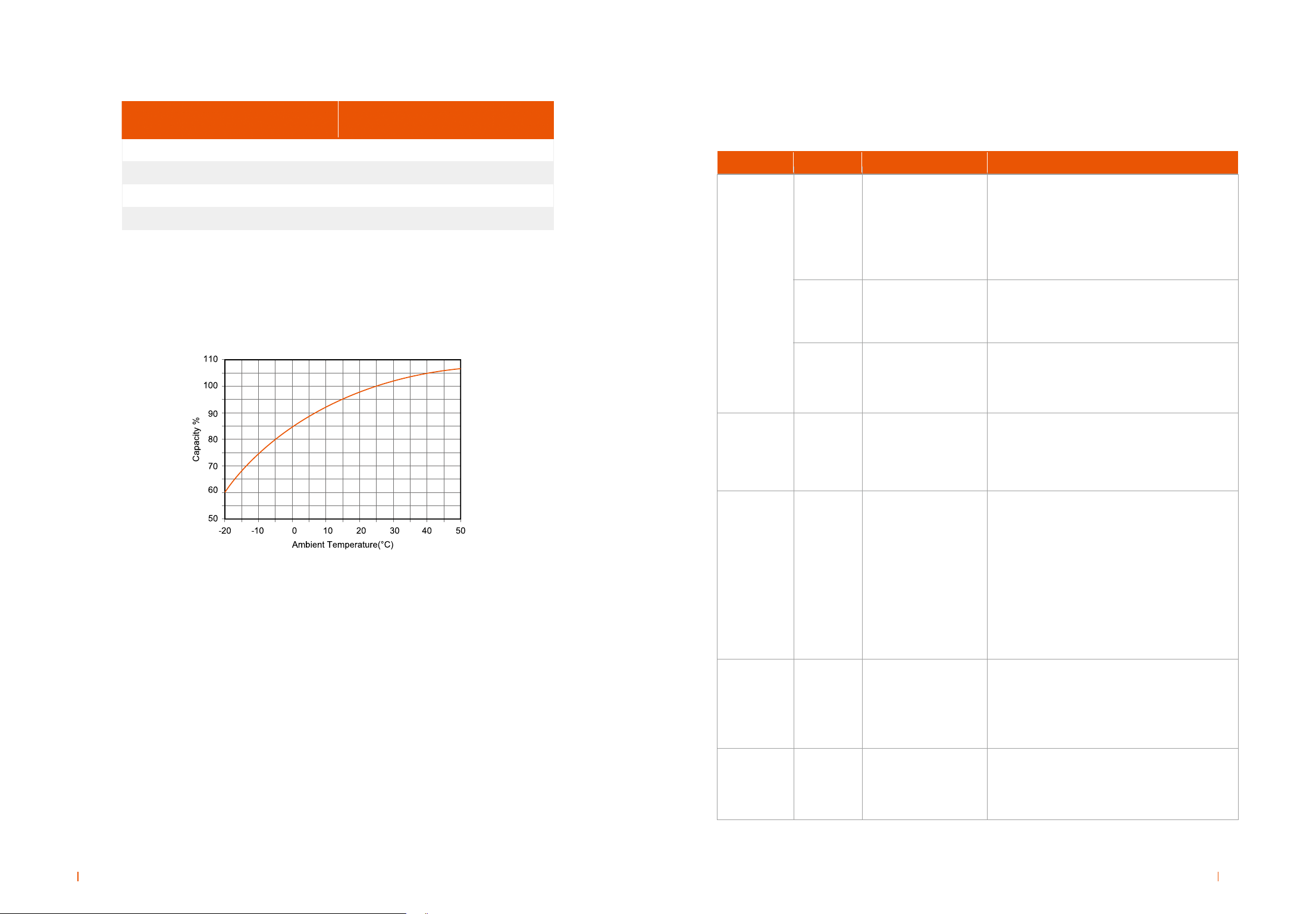
Temperature Compensate Ratio With
Floating Voltage(mV/°C per cell)
Temperature Compensate Ratio With
Equalization Voltage(mV/°C per cell)
Floating Voltage(V)
Equalization Voltage(V)
High Temperature Warning(°C)