NPFC Series LiFePO4Battery Module for Telecom
07 08
RS232 communication port just for software upgrade now.
communication
port
RS2325
It is adopting RS485 series port communication pattern
to upload data. Contents of data transmit include
BMS parameters, battery running status, alarms, etc.
Communication of modules connected in parallel is
available through RS485.
Press RESET button when abnormity occurs to assure
stability of battery performance.
Battery BMS can be removable and replace easily through
this.
The side mounting is used to wall-handing installation battery.
Also use the ear to handle the battery.
Failure Alarm: indicate BMS or battery fail including but
not limited to charge and discharge MOS fail, cell voltage
under 0.5V, NTC disconnect, and so on.
When turn-off, battery get into sleep mode, and cut-off
output, the alarm output also will be stopped.
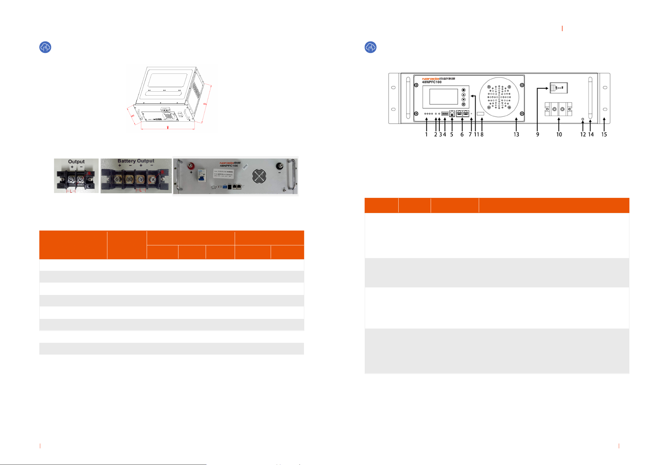
Using terminals with four or two cores. Polarities are +, -,
+, - from left to right. The two ‘+’ and ‘-’ are equal relatively.
Detailed information is shown in Fig. 1-2.
Connect earth by exible cable above GREEN Sheathed,
UL94-V0, gauge of the grounding wire should be equal to
or greater than the gauge of the battery return wire.
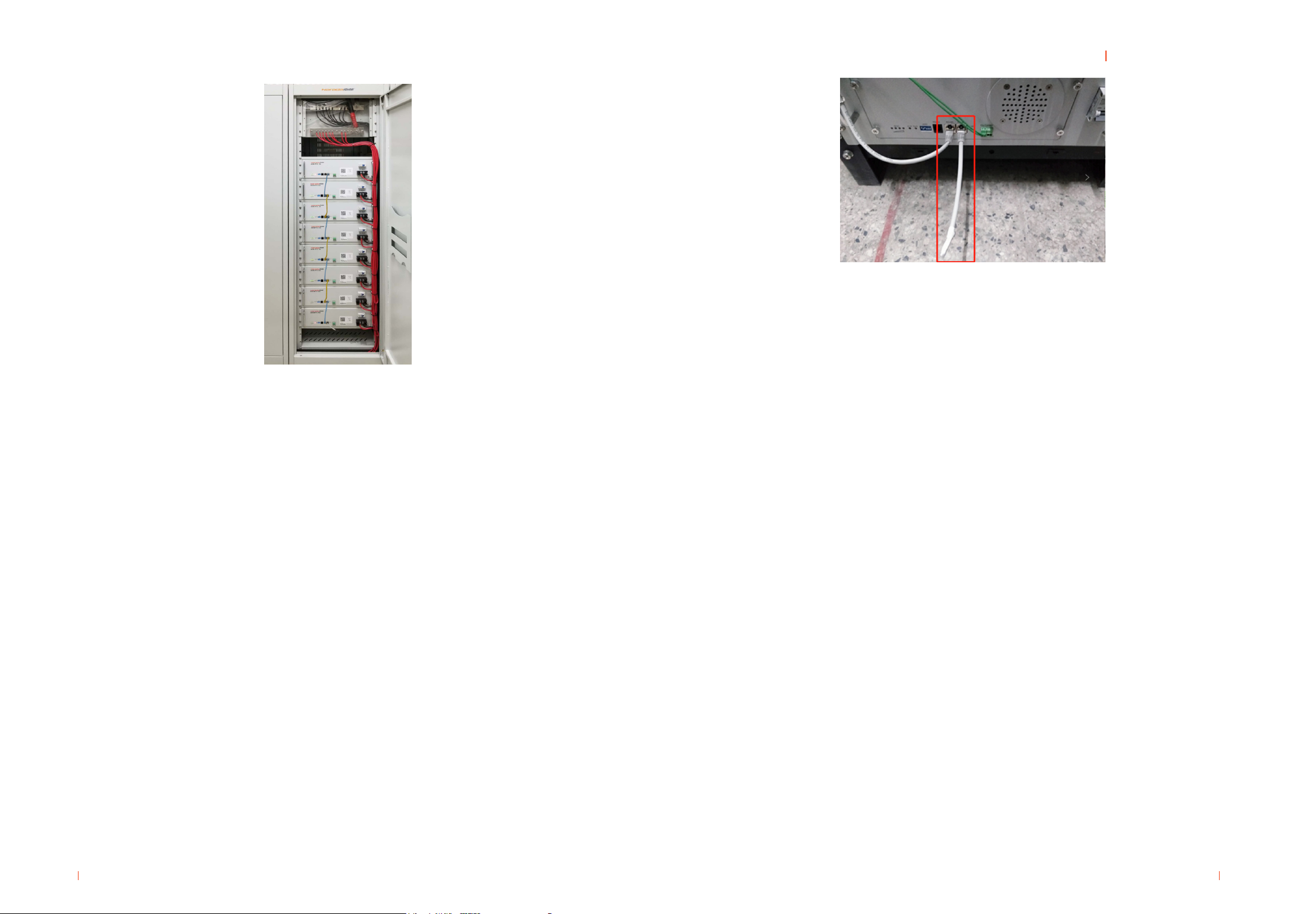
The handle is used to push and pull the battery easily
from battery cabinet.
Not recommend use handle to handing the battery.
Detailed information is shown in Annexed Table 3.
Dry contact
indicators
Terminals for
battery output
Display battery
information
Ground screw
handle
ON/OFF switch
communication
port
Reset button
Removable
Panel
Wall-hanging
installation
RS485
RESET
Removable
Panel
(optional)
Side
mounting
Dry
contact
Battery
Output
LCD
(optional)
GND
Handle
Power
switch
6
8
10
9
11
12
14
7
13
15
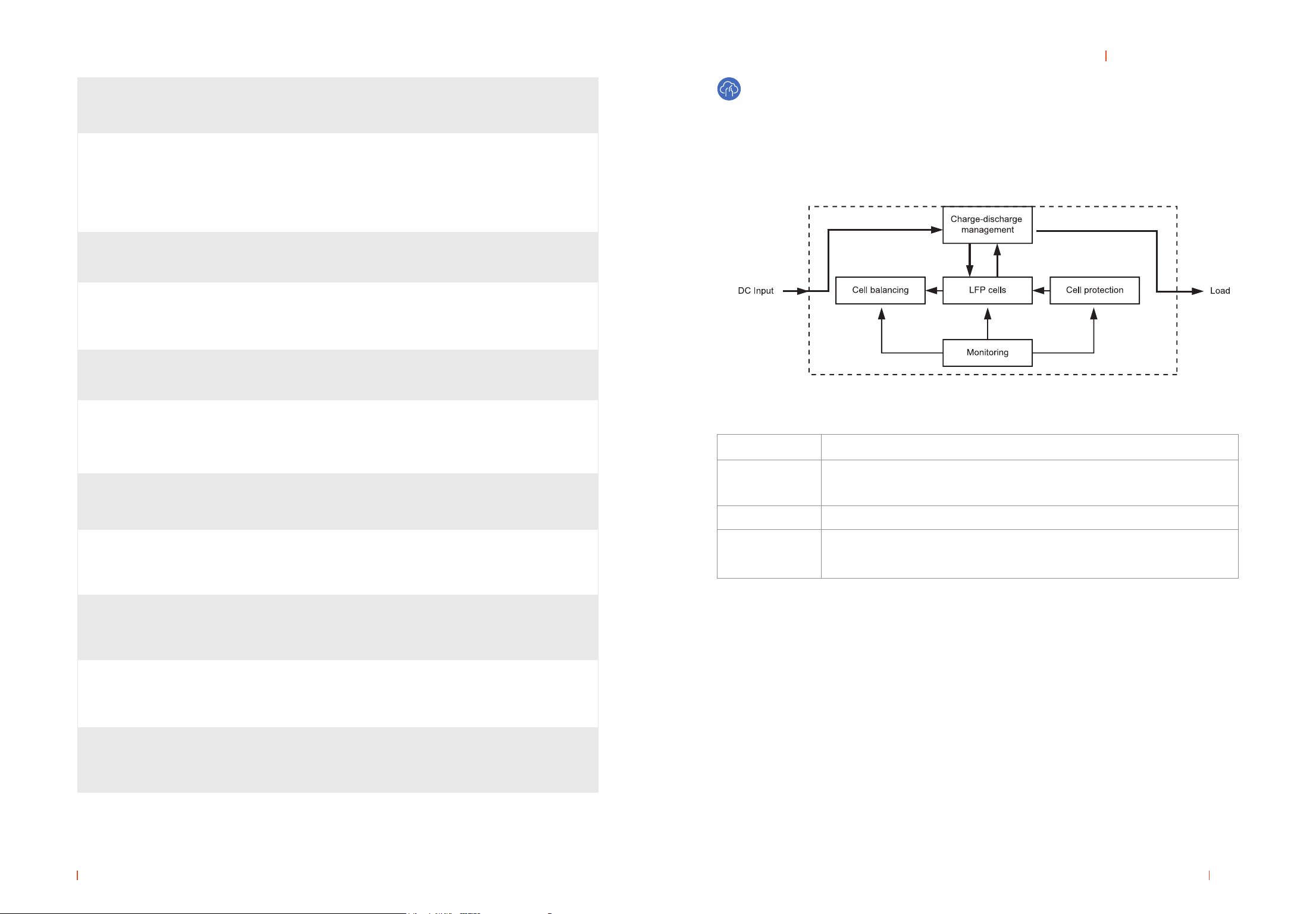
Working Principle
The NPFC battery system mainly includes Lithium battery pack, battery protection, cell balancing
unit, monitoring module and charge-discharge management module for optional. Its schematic
diagram shown in Figure 1-4
Fig. 1-4 Schematic Diagram
LFP cells
Cell protection
Cell balancing
Monitoring
Chemical power, energy storage and power supply components.
Protect LFP cells against overcharge, over discharge, over current, over
temperature, short circuit
Equalization LFP cells for cells unbalanced
Support centralized monitoring system (optional according to customer
requirements)
NPFC battery working principle:
DC power input rectier after lter, DC divided two circuits, one circuit directly supply the load, another
circuit charge lithium battery. When grid power on, the system supplies the loads and charging inside
lithium batteries; When grid power failure, lithium inside system supply DC power to the load, to
ensure uninterrupted power supply as power system.
Battery Management System (BMS)
Smart BMS technology is adopted for battery modules of NPFC series to assure smart automatic
management for batteries. Features of BMS are shown as below: