NARGESA TS10 User manual

INSTRUCTIONS BOOK
PRADA NARGESA, S.L
Ctra. de Garrigàs a Sant Miquel s/n · 17476 Palau de Santa Eulàlia (Girona) SPAIN
Tel. +34 972568085 · [email protected] · www.nargesa.com
WELD POSITIONER
TS10

Thank you for choosing our machines
www.nargesa.com

INSTRUCTIONS BOOK OF WELD POSITIONER TS10 2
INDEX
1. CHARACTERISTICS OF THE MACHINE ...............................................................................
1.1. Identification of the machine .......................................................................................
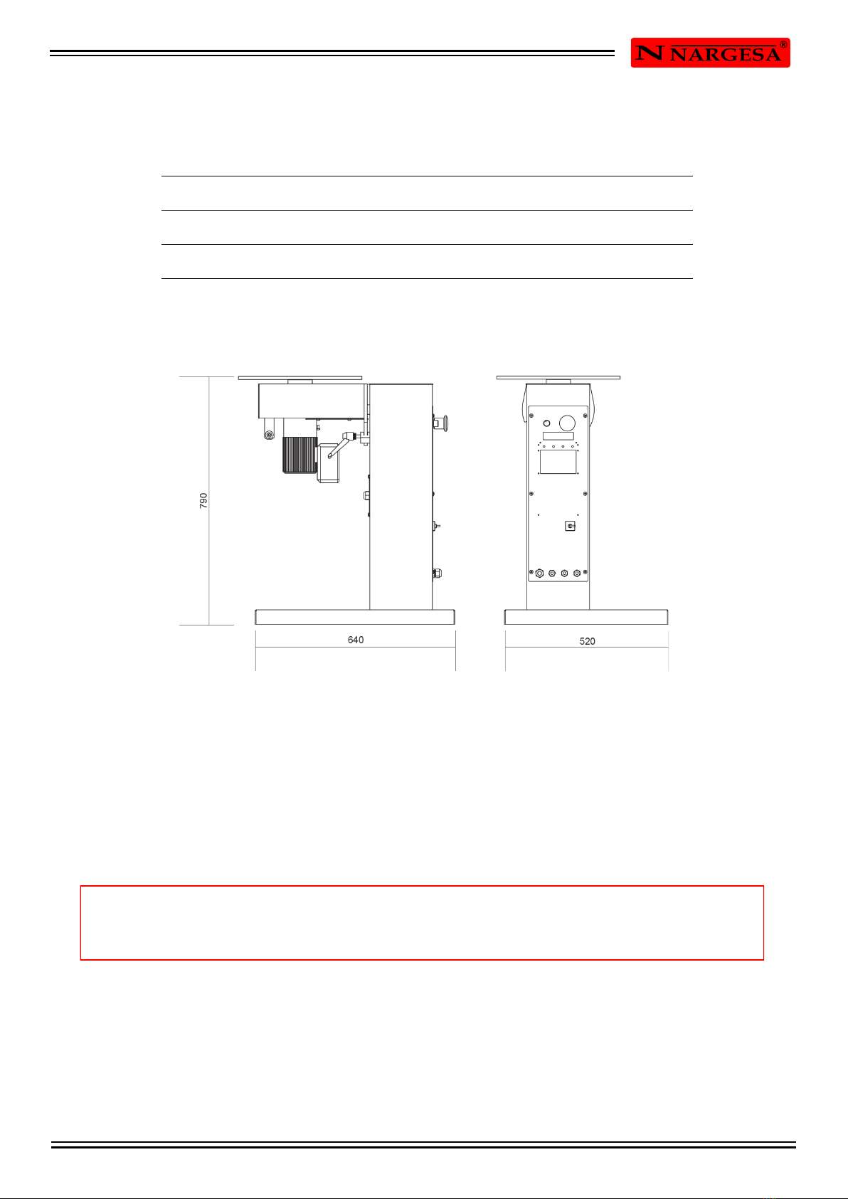
1.2. Dimensions .................................................................................................................
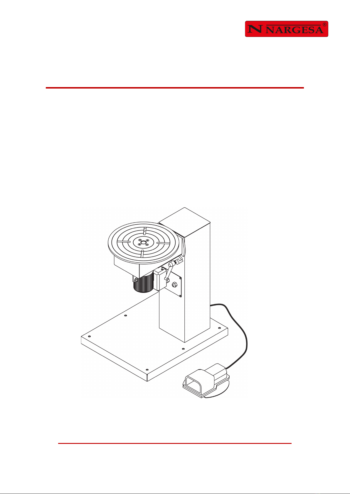
1.3. Description of the machine ..........................................................................................
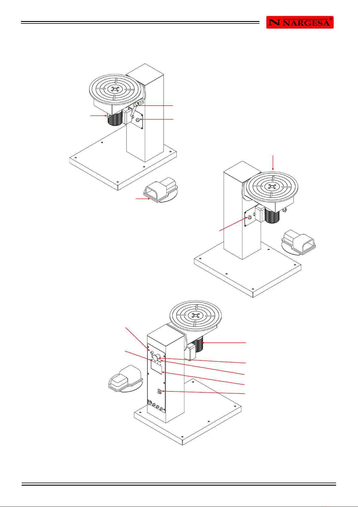
1.4. Identification of the components .................................................................................
1.5. General characteristics ...............................................................................................
2. TRANSPORT AND STORAGE ...............................................................................................
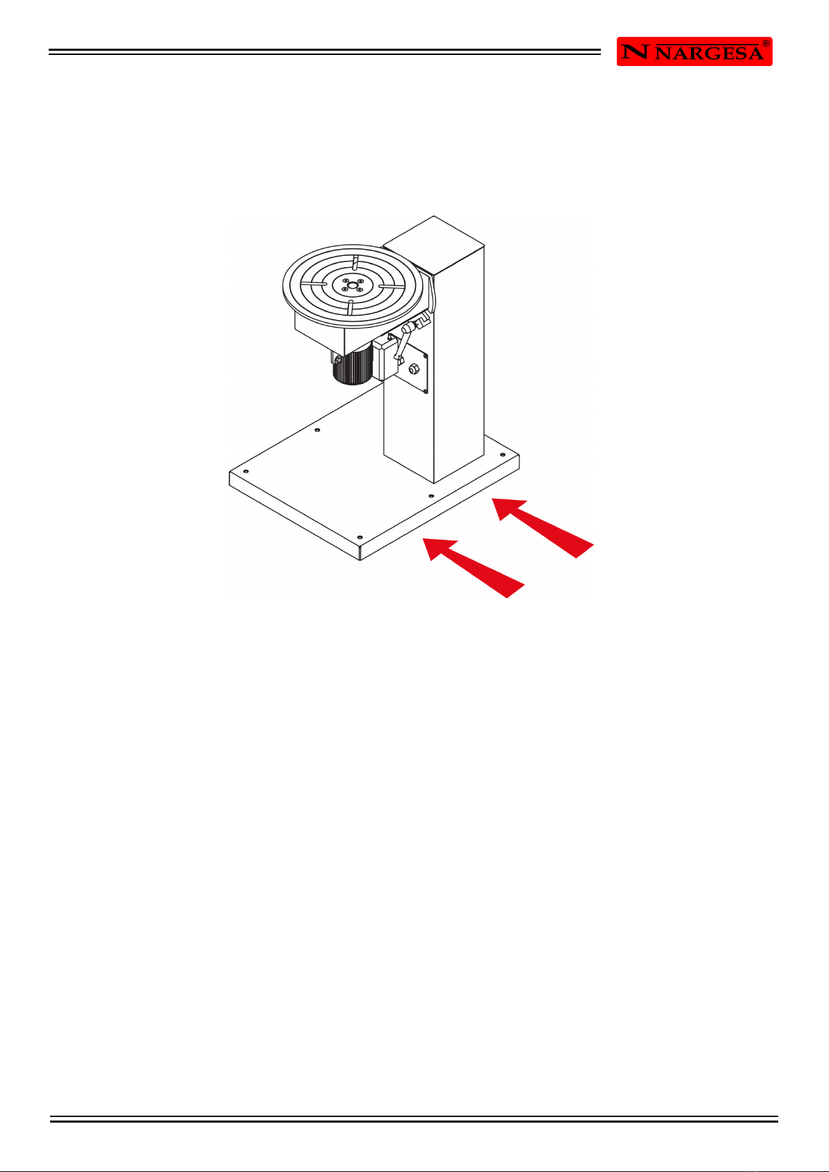
2.1. Transport .....................................................................................................................
2.2. Storage conditions ......................................................................................................
3. INSTALMENT AND STARTING UP ........................................................................................
3.1. Location of the machine ..............................................................................................
3.2. Admissible outer conditions ........................................................................................
3.3. Connection to the power supply ..................................................................................
4. INSTRUCTIONS FOR USE .....................................................................................................
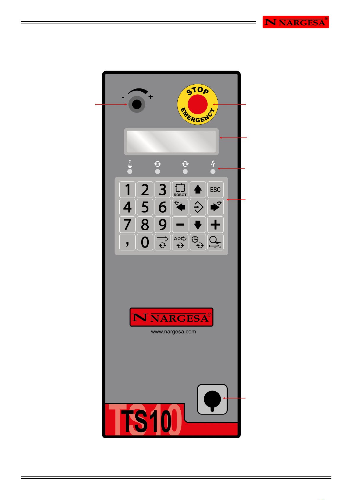
4.1. Panel description .........................................................................................................
4.2. Introduction .................................................................................................................
4.3. Feeding of the Positioner TS10 ...................................................................................
4.4. Activation of the Positioner TS10 ................................................................................
4.5. Memories of continous welding ...................................................................................
4.6. Memories of discontinous welding ..............................................................................
4.7. Robot mode .................................................................................................................
4.8. Memories of continous welding at robot mode ............................................................
4.9. Memories of discontinous welding at robot mode .......................................................
5. WARNINGS .............................................................................................................................
TECHNICAL ANNEX
3
3
3
3
4
5
6
6
6
7
7
7
7
8
8
10
10
10
11
12
14
15
16
19

INSTRUCTIONS BOOK OF WELD POSITIONER TS10 3
1. CHARACTERISTICS OF THE MACHINE
1.1. Identification of the machine
1.2. Dimensions
Picture 1. External dimensions of the Weld positioner
1.3. Description of the machine
TS10 has been designed to weld different circular parts in different positions and kinds of welding.
TS10, is according to the European regulations and normative for the manufacturing of machinery
If an accident occurs by negligence of the operative, for not following the safety rules exposed
on this manual, PRADA NARGESA S.L will not accept any responsibility.
Trademark Nargesa
Type Weld positioner
Model TS10

INSTRUCTIONS BOOK OF WELD POSITIONER TS10 4
1.4. Identificación de los componentes
Picture 2. Nomenclature and position of components
Connection for the
welding pincers
Oparation pedal
Encoder hose
Potenciometer to regulate
turning speed
LED’S light pilots
Slant regulation handle
Engine hose
Turning plate
Motor reducer
Emergency stop
Information display
Operations keyboard
Main switch

INSTRUCTIONS BOOK OF WELD POSITIONER TS10 5
Picture 3. Features plate
1.5. General characteristics
Motor reducer 0,12 KW / 0,16 CV
2 phased tension 230 V
Speed 60º/s
Route of the programmable bench 0º - 360º
Slant regulation 0º - 100º
Welding type Continous or discontinous
Horizontal maximum capacity 75 Kg
Vertical maximum capacity 55 Kg
Round plate diemeter 395 mm
Plate thickness 10 mm
Bench height 790 mm
Dimensions 520x640x790 mm
Weight 61 Kg

INSTRUCTIONS BOOK OF WELD POSITIONER TS10 6
2. TRANSPORT AND STORAGE
2.1. Transport
Transport with no elevation will be carried out by using a forklifting truck.
Picture 4. Transportation of the machine
2.2. Storage conditions
TS 10 must be placed in a site with the following requirements:
* Humidity between 30% and 95% without water condensation.
* Temperature from -25 to 55ºC or 75ºC for length of time no longer than 24h
* It is advisable not to pile up machines or heavy objects on top of them.
* Do not dismantle for storage.

INSTRUCTIONS BOOK OF WELD POSITIONER TS10 7
IMPORTANT: This machine must be connected to a socket with ground connection.
3. INSTALMENT AND STARTING UP
3.1 Location of the machine
The machine will be properly placed so it doesn have to be moved, in case this is not possible then follow
the steps described in the transport section (nº2). It will be put in a flat surface to avoid vibrations and
movements of it during performance. It is possible to fix the machine by using bolts since it is provided with
a lower base or foot with 6 holes as it is shown in the picture.
Figura 5. Puntos de anclaje de la máquina
3.2. Admissible outer conditions
- Environmental temperature between +5ºC and +40ºC without exceding an average temperature of +35ºC
for the 24h
- Humidity from between 30% and 90% without water condensations.
3.3 Connection to the power supply
TS10 is equipped with a 230v and 0.12 kW single phased engine to be connected to a 230v power supply.
It must be connected to an only power supply in the indicated source.

INSTRUCTIONS BOOK OF WELD POSITIONER TS10 8
4. INSTRUCTIONS FOR USE
4.1. Panel description
Picture 6. Control panel of the Welding Positioner.
Potenciometer to
regulate turning
speed
Emergency button
Information display
LED’S light pilots
Operations keyboard
Main switch

INSTRUCTIONS BOOK OF WELD POSITIONER TS10 9
NUMERICAL FUNCTION KEYS TO INTRODUCE DATA
KEY TO CONFIRM OR VALIDATE DATA
ESCAPE KEY TO RETURN MAKE ONE STEP BACK
ARROWS TO SELECT UPWARDS DIRECTION
ARROWS TO SELECT DOWNWARDS DIRECTION
KEY TO ACCEDE THE CONTINOUS WELDING MEMORIES MENU
KEY TO ACCEDE THE DISCONTINOUS WELDING MEMORY MENU
KEYS FUNCTION DIN JUST FOR THE USE OF THE ROBOT
INDICATES THE TURNING DIRECTION OF THE PLATE TO THE RIGHT
INDICATES THE TURNING DIRECTION OF THE PLATE TO THE LEFT
IT ALLOWS THE ACCESS TO THE TIME PARAMETER OF
STARTING OF THE WELDING PROCESS (WELDING STOKING TIME)
IT ALLOWS THE ACCESS TO OVERLAPPING PARAMETER
(IT SURPASSES WELDING FROM 360º)
IT ALLOWS ACCESS TO PERFORMANCE OF THE TS-10
WITH A WELDING ROBOT

INSTRUCTIONS BOOK OF WELD POSITIONER TS10 10
NARGESA
TS - 10
TS - 10
STARTING
TURNING TO THE RIGHT
POSITION 0º
SPEED 10º/S
POSITION 0º
4.2 Introduction
This book has been designed as a tool for the user of the machine Welding Positioner TS 10, since it has
got important information about its use and peculiarities. Therefore it is advisable to follow step by step all
points detailed in this manual for the correct comprehension of the machine performance.
4.3. Feeding of the Positioner TS10
In order to feed up the machine, just put the Start switch in the plugged position. Then it will appear a
message like the one below on screen:
Picture 7. Activation message of the TS10
4.4. Activation of the Positioner TS10
In order to proceed properly, please, press the ESC key. Then and just in case you finish feeding up the
machine, as it has been described before it will appear an initialization message in the LCD display, while
the machine is getting position in “0” absolute.
Picture 8. Initialization message of TS10
Once there, a label like the next one will show up on the screen:
Picture 9. Rest screen of TS10
This is the default mode to start the control. Now its performance is completely manual, that is to say, the
welding plate turns when the pedal is pressed. When the pedal is no longer pressed the positioner stops
turning.
The turning direction is previously set by pressing the key according to the desired direction. (Left or Right).
If in this moment we press the pedal, the positioner starts turning in the indicated direction while it shows
on screen the the speed and current angle like in the label below:
Picture 10. Information of TS10 in positioner mode

INSTRUCTIONS BOOK OF WELD POSITIONER TS10 11
CONTINOUS
WELDING: 0
MSC00-> -> POSIT
END ANGLE 90º
MSC00-> -> POSIT
>>>>>>>>>> 120º
MSC00-> -> POSIT
OVERLAP 20º
MSC00-> -> POSIT
START TIME 3 S
You can change the turning speed pf the welding plate by adjusting the potentiometer located in the upper
left part.
4.5. Memories of continous welding
To accede this manu just press the key for Continous welding. Once you do it, it will appear on screen a list
with the ten available memories. The selection of the proper memory is made by using the selection arrows
(upwards and downwards) and then press OK.
Picture 11. Information of the current continuous welding memory.
After selecting the memory, the weld positioner will place in the starting point of this memory. At this
moment either a given memory could be edited or it could go to operate with this one.
Edition will be carried out as follwos:
· Changing the value of End Welding is done directly with the numeric keypad.
Picture 12. Screen of the continuous welding memory
Picture 13. Screen for the modification of the continuous welding memory
· The Starting Time key gives direct access to the parameter of this memory.
Picture 14. Screen for Weldinf Starting Time
· The Overlapping key gives direct access to the parameter of this memory whenever the memory is 360º.
Picture 15. Overlapping angle screen

INSTRUCTIONS BOOK OF WELD POSITIONER TS10 12
MSC00-> -> POSIT
END ANGLE 90º
MSC00 <- <- POSIT
END ANGLE 90º
DESTINATION 360º
CURRENT 0º
DISCONTINOUS: 00
WELDING
· The Left or Right turning direction keys determine the welding plate turning direction since they both work
with the same current memory.
Picture 16. Screen for Right turning direction
Picture 17. Screen for left turning direction
The operation with a given memory is carried out as follows, afetr placeing the piece in the plate:
The welding starts, following the parameters of it and in the specified.
Picture 18. Screen for Continuous welding memory
· Once the welding sequence is finished, the weld positioner will go back again to the Welding Starting
Point.
4.6. Memories of discontinous welding
For circular welding allowing to make points or just sections of welding.
It accede the discontinuous weldinig memories pressing the key for discontinuous welding. Once you do
this, a list with the 10 existing discontinuous memories will show up on screen. The selection has been
made by using the moving keys (up and down arrows) and pressing the OK key.
Picture 19. Information of the current discontinuous welding memorys

INSTRUCTIONS BOOK OF WELD POSITIONER TS10 13
MSD00 -> -> POSIT
INI ANGLE 0º
MSD00 -> -> POSIT
END ANGLE 360º
MSD00 -> -> POSIT
WELDING 15º
MSD00 -> -> POSIT
GAPS 10º
MSD00 -> -> POSIT
END ANGLE 90º
MSD00 <- <- POSIT
END ANGLE 90º
Now the following parameters will show up:
· Indication of the start and end of welding (in degrees).
Picture 20. Screen for discontinuous welding memory
Picture 21. Screen of Discontinuous welding memory
· Length od welding
Picture 22. Screen of the discontinuous welding memory
· Gap between welding
Picture 23. Screen for the discontinuous welding memory
For the turning direction parameters, starting time and overlapping, the access is made directly through the
function keys that are already set for that.
Picture 24. Screen for the Right turning dire
Picture 25. Screen for the Left turning direction

INSTRUCTIONS BOOK OF WELD POSITIONER TS10 14
MSD00 -> -> POSIT
START TIME 3 S
MSD00 -> -> POSIT
OVERLAP 20º
DESTINATION 360º
CURRENT 0º
Note: Remember all signs coming from the Robot must be Potential free.
Parameters start time and overlap also works in robot mode.
Picture 26. Screen for Starting time of welding
Picture 27. Screen for Overlapping angle
When pressing the pedal and let it loose then afer having introduced the piece, the indicated welding cicle
starts.
Picture 28. Screen for the discontinuous welding memory
When a welding operation ends, the plate will go again to the starting point of the memory currently
selected.
4.7. Robot mode
When pressing the Robot Key we are indicating the that the positioner will work with an outer welding
robot.In this case, the manual performance is cancelled. However the discontinuous and continuous
welding memories keep on performing exactly like in the Positioner Mode.
The only difference lies on how the Positioner operates, which is explained below.
· The positioner will go to absolute “0” or to the begining of the memory to be made.
· When pressing the pedal and let it loose again the welding cycle begins. The relay activates for the robot
to be placed in the starting point, make the linear welding and gives us the sign as it is in position to start
the rotary welding.
· Once it is detected that the robot is in that position, the second relay is used to indicate the moment
required for the robot to carry out the welding operation or not.
· When the welding is finished, the starting relay is cancelled so the robot goes to the rest position.
· The positioner will go back again in absolute “0” or Starting welding point.

INSTRUCTIONS BOOK OF WELD POSITIONER TS10 15
CONTINOUS : 00
WELDING
MSC00 -> -> ROBOT
END ANGLE 90º
MSC00 -> -> ROBOT
>>>>>>>>>>> 120º
MSC00 -> -> ROBOT
STARTING TIME 3 S
MSC00 -> -> ROBOT
SOLAP 20º
4.8. Memories of continous welding at robot mode
To accede this menu it is necessary to press the Continuous Welding key. Once it is made is appears on
screen a list with the ten available memories. The selection of the proper memory will be carried out with
the selection arrows. (Up and down arrows) and the pressing of the OK key.
Picture 29. Information of the current continuous welding memory
After selecting the memory, the positioner will go to the starting point of that memory, then a given memory
could be edited or it could go to work with this one.
Edition will be carried out as follows:
· Changing the value of End Welding is done directly with the numeric keypad.
Picture 30. Screen for the continuous memory welding
Picture 31. Screen for the modification of the continuous welding memory
· The Starting Time Key gives direct access to to the parameter of this memory
Picture 32. Screen for Welding starting point
· The Overlapping key gives direct access to this parameter on the memory whenever it is 360º.
Picture 33. Screen for the Overlapping Angle

INSTRUCTIONS BOOK OF WELD POSITIONER TS10 16
MSC -> -> ROBOT
END ANGLE 90º
MSC <- <- ROBOT
END ANGLE 90º
DESTINATION 360º
CURRENT 0º
DISCONTINOUS : 00
WELDING
MSD00 -> -> ROBOT
START ANG 0º
· The Right or Left turening direction arrows determine the welding plate turning direction when working
with the current memory.
Picture 34. Screen for right turning direction
Picture 35. Screen for Left turning direction
The operation with a given memory is carried out as follows, after placing the piece in the plate:
· The welding starts following the parameters of this with the specified sense.
Picture 36. Screen of the continuous welding memory
· Once the welding sequence is finished, the positioner goes back again to the Welding Starting Point.
4.9. Memories of discontinous welding at robot mode
To accede to the discontinuous welding memories just press the Discontinuous welding keys It will appear
then a list with the ten existing discontinuous memories. The selection will be made by using the moving
keys. (Up and down arrows) and pressing the OK key.
Picture 37. Information of the current discontinuous memory
Now the following parameters will appear.
. Indication of the start and end of the welding. (In degrees)
Picture 38. Screen of the discontinuous welding memory

INSTRUCTIONS BOOK OF WELD POSITIONER TS10 17
MSD00 -> -> ROBOT
END ANGLE 360º
MSD00 -> -> ROBOT
WELDING 15º
MSD00 -> -> ROBOT
DISTANCE 10º
MSD00 -> -> ROBOT
END ANGLE 90º
MSD00 <- <- ROBOT
END ANGLE 90º
MSD00 <- <- ROBOT
STARTING TIME 3 S
MSD00 <- <- ROBOT
SOLAP 20º
Picture 39. Screen of the discontinuous welding memory
· Welding length.
Picture 40. Screen of the discontinuous welding memory
· Gap between welding.
Picture 41. Screen of the discontinuous welding memory
To accede the turning direction parameters, starting time and overlapping go through the function keys that
are already set for that.
Picture 42. Screen of the right turning direction
Picture 43. Screen of Left turning direction
Picture 44. Screen of Welding Start Time
Picture 45. Screen of Overlapping angle

INSTRUCTIONS BOOK OF WELD POSITIONER TS10 18
DESTINATION 360º
CURRENT 0º
When pressing the pedal and then let it loose, after having introduced the piece to be worked, the indicated
welding cycle begins.
Picture 46. Screen of Pantalla de Memoria de soldadura discontinua
When a welding operation ends, the plate locates in a new starting point of the memory that has been
currently selected.

INSTRUCTIONS BOOK OF WELD POSITIONER TS10 19
5. WARNINGS
- Do not handleany component of the machine while this one is performing.
- Do not use the machine for any other purpose but the ones described in this manual.
- Wear safety googles and boots according to the EC regulations.
- Keep a safety distance between the machine and the operative during the time the machine is performing.
-In case an accident due to a negligent use of the operative, for not bearing in mind the safety rules
exposed on this book, NARGESA SL will not accept any responsibility.
Table of contents
Popular Welding Accessories manuals by other brands

DINSE
DINSE DIX EL 400 Operation manual

Weldability Sif
Weldability Sif SifLITE Revenge FXADF700 Series user manual

Miller Electric
Miller Electric XMT 4-Rack owner's manual

Amada
Amada MacGregor DC 13-T Series Hardware manual

Goldschmidt
Goldschmidt Thermit SMARTWELD RECORD Brief instructions

Fujikura
Fujikura 36S instruction manual

Everlast
Everlast PowerCool 375 Operator's manual

Lincoln Electric
Lincoln Electric DownFlex 100-NF Operator's manual

Miller
Miller VL-M4 owner's manual

Raider
Raider RD-PW02L user manual

Magswitch Technology Inc.
Magswitch Technology Inc. Multi-Angle 400 Magvise Operation and instruction manual

ITW
ITW orbitalum TX 38P Translation of original operating instructions