4
Installation Guide |Defrost Board Replacement Kit
• ENSURE THAT ALL POWER IS DISCONNECTED
PRIOR TO ATTEMPTING INSTALLATION OF THIS
HEATER KIT. THERE MAY BE MORE THAN ONE
DISCONNECT SERVICING THE UNIT.
• A MEANS OF STRAIN RELIEF AND CONDUCTOR
PROTECTION MUST BE PROVIDED AT THE
SUPPLY WIRE ENTRANCE INTO CABINET.
• USE COPPER CONDUCTORS ONLY.
• INSTALLATION MUST FOLLOW NATIONAL
ELECTRIC CODE ANDOTHER APPLICABLE
CODES.
If this appliance is installed in an enclosed area
such as a garage or utility room with any carbon
monoxide producing appliance, ensure the area is
properly ventilated.
Safety Warnings!
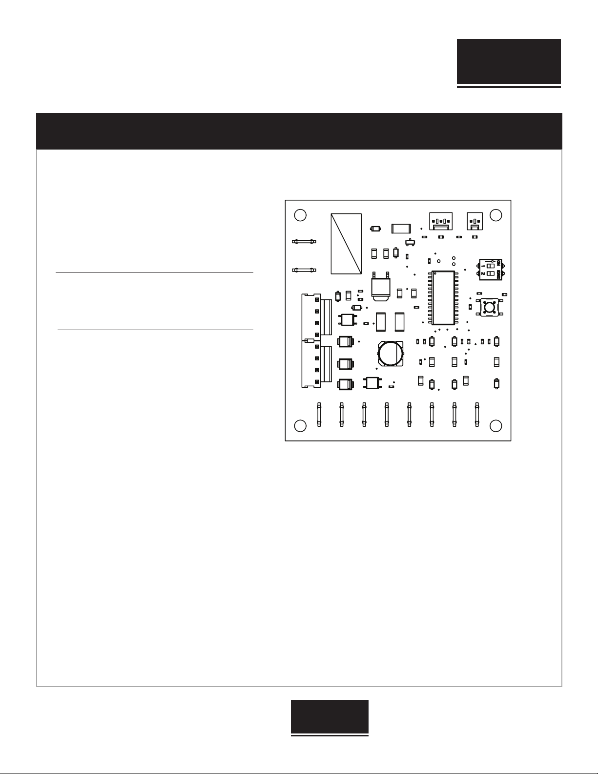
Defrost Board Replacement
Kit Compatibility
Replacement Models:
NCHP-018-1019
NCHP-018-3019
NCHP-024-1019
NCHP-024-3019
NCHP-030-1019
NCHP-030-3019
NHPA-418-3019
NHPA-418-5019
NHPA-424-3019
NHPA-424-5019
NHPA-430-3019
NHPA-430-5019
ATTENTION INSTALLING PERSONNEL
HIGH VOLTAGE! Disconnect ALL power before servicing.
Multiple power sources may be present. Failure to do so may
result in property damage, personal injury or death.
!WARNING
!WARNING
!WARNING
These instructions are intended as an aid to qualied, licensed
service personnel for proper installation, adjustment and operation of
this unit. Read these instructions thoroughly before attempting
installation or operation. Failure to follow these instructions may
result in improper installation, adjustment, service or maintenance
possibly resulting in re, electrical shock, property damage, personal
injury or death.
Installation and repair of this unit should be performed ONLY by
individuals meeting the requirements of an “entry level technician” as
specied by National Codes. Attempting to install or repair this unit
without such background may result in product damage, personal
injury or death.
!CAUTION
ALL phases of this installation must comply with NATIONAL, STATE
AND LOCAL CODES. The manufacturer assumes no responsibility for
equipment installed in violation of any code requirements.
Be sure that the electrical data specied on the unit rating plate
corresponds to what is available at the installation site and NEC for
installation requirements.
Be sure that the electrical service provided to the building can handle
the load imposed by the unit.
“USE COPPER SUPPLY WIRES ONLY”
DSHP models may require further modication
*Only compatible with models that use the ICM 321
Defrost Board.
*List is subject to change without notice.