National Instruments IVN-8561 User manual

IVN-8561
Getting Started
2022-07-11

Contents
Overview. . . . . . . . . . . . . . . . . . . . . . . . . . . . . . . . . . . . . . . . . . . . . . . . . . . . . . . . . . . . . . . . . . . . . . 3
Safety Guidelines. . . . . . . . . . . . . . . . . . . . . . . . . . . . . . . . . . . . . . . . . . . . . . . . . . . . . . . . . . . . 3
Electromagnetic Compatibility Guidelines. . . . . . . . . . . . . . . . . . . . . . . . . . . . . . . . . . . . . . 3
Electromagnetic Compatibility. . . . . . . . . . . . . . . . . . . . . . . . . . . . . . . . . . . . . . . . . . . . . . . . 4
CE Compliance. . . . . . . . . . . . . . . . . . . . . . . . . . . . . . . . . . . . . . . . . . . . . . . . . . . . . . . . . . . . . . 4
Product Certifications and Declarations. . . . . . . . . . . . . . . . . . . . . . . . . . . . . . . . . . . . . . . . 4
Unpacking the Kit. . . . . . . . . . . . . . . . . . . . . . . . . . . . . . . . . . . . . . . . . . . . . . . . . . . . . . . . . . . . 5
Verifying the Kit Contents. . . . . . . . . . . . . . . . . . . . . . . . . . . . . . . . . . . . . . . . . . . . . . . . . . . . . 5
Power Requirements. . . . . . . . . . . . . . . . . . . . . . . . . . . . . . . . . . . . . . . . . . . . . . . . . . . . . . . . . 5
Preparing the Environment. . . . . . . . . . . . . . . . . . . . . . . . . . . . . . . . . . . . . . . . . . . . . . . . . . . 6
Hardware Overview. . . . . . . . . . . . . . . . . . . . . . . . . . . . . . . . . . . . . . . . . . . . . . . . . . . . . . . . . . 6
Cabling Requirements. . . . . . . . . . . . . . . . . . . . . . . . . . . . . . . . . . . . . . . . . . . . . . . . . . . 7
LEDs. . . . . . . . . . . . . . . . . . . . . . . . . . . . . . . . . . . . . . . . . . . . . . . . . . . . . . . . . . . . . . . . . . . 7
Master/Slave Switches. . . . . . . . . . . . . . . . . . . . . . . . . . . . . . . . . . . . . . . . . . . . . . . . . . . 8
DIN Rail Mounting. . . . . . . . . . . . . . . . . . . . . . . . . . . . . . . . . . . . . . . . . . . . . . . . . . . . . . . 8
Wiring the IVN-8561. . . . . . . . . . . . . . . . . . . . . . . . . . . . . . . . . . . . . . . . . . . . . . . . . . . . . . . . . . 9
Pin Assignments. . . . . . . . . . . . . . . . . . . . . . . . . . . . . . . . . . . . . . . . . . . . . . . . . . . . . . . . 9
Connecting the IVN-8561. . . . . . . . . . . . . . . . . . . . . . . . . . . . . . . . . . . . . . . . . . . . . . . . . . . . 10
Functional Diagram. . . . . . . . . . . . . . . . . . . . . . . . . . . . . . . . . . . . . . . . . . . . . . . . . . . . . . . . . 10
Where to Go Next. . . . . . . . . . . . . . . . . . . . . . . . . . . . . . . . . . . . . . . . . . . . . . . . . . . . . . . . . . . 11
NI Services. . . . . . . . . . . . . . . . . . . . . . . . . . . . . . . . . . . . . . . . . . . . . . . . . . . . . . . . . . . . . . . . . 11
ni.com
2
IVN-8561 Getting Started

Overview
POWER
5V
2.8W MAX
#6-32
PORT 4
MASTER
POWER
P1
P3
LINK/ACT
IVN-8561
100BASE-T1 Media Converter
This document describes how to begin using the IVN-8561 100BASE-T1 Media
Converter. The IVN-8561 is a two-channel, four-port media converter that converts
data between 100BASE-TX Ethernet and 100BASE-T1 Automotive Ethernet with
minimal latency.
Safety Guidelines
Operate the IVN-8561 only as described in this document.
Caution This icon denotes a caution advising you to take precautions to
avoid injury.
Caution Do not operate the IVN-8561 in a manner not specified in this
document. Product misuse can result in a hazard. You can compromise the
safety protection built into the product if the product is damaged in any
way. If the product is damaged, return it to NI for repair.
© National Instruments 3
IVN-8561 Getting Started

Electromagnetic Compatibility Guidelines
This product was tested and complies with the regulatory requirements and limits
for electromagnetic compatibility (EMC) stated in the product specifications. These
requirements and limits provide reasonable protection against harmful interference
when the product is operated in the intended operational electromagnetic
environment.
This product is intended for use in industrial locations. However, harmful
interference may occur in some installations, when the product is connected to a
peripheral device or test object, or if the product is used in residential or
commercial areas. To minimize interference with radio and television reception and
prevent unacceptable performance degradation, install and use this product in strict
accordance with the instructions in the product documentation.
Furthermore, any changes or modifications to the product not expressly approved
by National Instruments could void your authority to operate it under your local
regulatory rules.
Electromagnetic Compatibility
CE Compliance
This product meets the essential requirements of applicable European Directives, as
follows:
■2014/35/EU; Low-Voltage Directive (safety)
■2014/30/EU; Electromagnetic Compatibility Directive (EMC)
■2011/65/EU; Restriction of Hazardous Substances (RoHS)
■2014/53/EU; Radio Equipment Directive (RED)
■2014/34/EU; Potentially Explosive Atmospheres (ATEX)
Product Certifications and Declarations
Refer to the product Declaration of Conformity (DoC) for additional regulatory
compliance information. To obtain product certifications and the DoC for NI
ni.com
4
IVN-8561 Getting Started

products, visit ni.com/product-certifications, search by model number, and click the
appropriate link.
Unpacking the Kit
Notice To prevent electrostatic discharge (ESD) from damaging the
device, ground yourself using a grounding strap or by holding a grounded
object, such as your computer chassis.
1. Touch the antistatic package to a metal part of the computer chassis.
2. Remove the device from the package and inspect the device for loose
components or any other sign of damage.
Notice Never touch the exposed pins of connectors.
Note Do not install a device if it appears damaged in any way.
3. Unpack any other items and documentation from the kit.
Store the device in the antistatic package when the device is not in use.
Verifying the Kit Contents
Verify the following components are in your kit.
■ IVN-8561, 100BASE-T1 Media Converter
■USB cable assembly, Type-C (male) to Type-A (female), 1 m
■Connector plug (QTY 2)
■Screwdriver, 2 mm, flathead
■Documentation
© National Instruments 5
IVN-8561 Getting Started

Power Requirements
Input voltage range 5 VDC nominal; USB 3.0 Type C
Max power consumption 2.8 W
Preparing the Environment
Ensure that the environment in which you are using the IVN-8561 meets the
following specifications.
Ambient temperature range -20 °C to 55 °C (Tested in accordance with IEC 60068-2-1 and IEC
60068-2-2.)
Relative humidity range 10% to 90%, noncondensing (Tested in accordance with IEC
60068-2-56.)
Maximum Altitude 2,000 m (800 mbar)
Pollution Degree 2
Indoor use only.
Note Refer to the device specifications on http://www.ni.com/manuals for
complete specifications.
Hardware Overview
The IVN-8561 has a total of four communication ports, and one USB port for power.
Ports 1 and 3 are 100BASE-T1 ports for Automotive Ethernet connections using two-
position terminal blocks. Ports 2 and 4 are 100BASE-TX ports for Ethernet
connections using 8-pin, modular RJ-45 connectors.
The 100BASE-T1 interfaces use an NXP TJA1100 100 Mbit/s BroadR-Reach-compliant
PHY. Weidmuller OMNIMATE SL-SMT 3.50/02/90LF terminal block headers are used
to connect to these ports. Compatible plugs are included with the IVN-8561.
Each 100BASE-T1 port can be configured as master or slave, using switches on the
front panel.
ni.com
6
IVN-8561 Getting Started

The power connector is USB Type-C. Use the USB cable (Type-C to Type-A) included
with the IVN-8561 to power the device from a standard USB 3.0 port on your
computer or industrial controller. The IVN-8561 can be powered from the USB port
of any NI PXI, CompactRIO, or industrial controller.
Cabling Requirements
Cabling for port 1 and port 3 connections must be 100BASE-T1 compliant, shielded
or unshielded twisted pair cable, with a maximum length of 15 m and cable
impedance of 100 Ω ±10%. Cabling for port 2 and port 4 connections must be Cat 5e
or higher Ethernet cable.
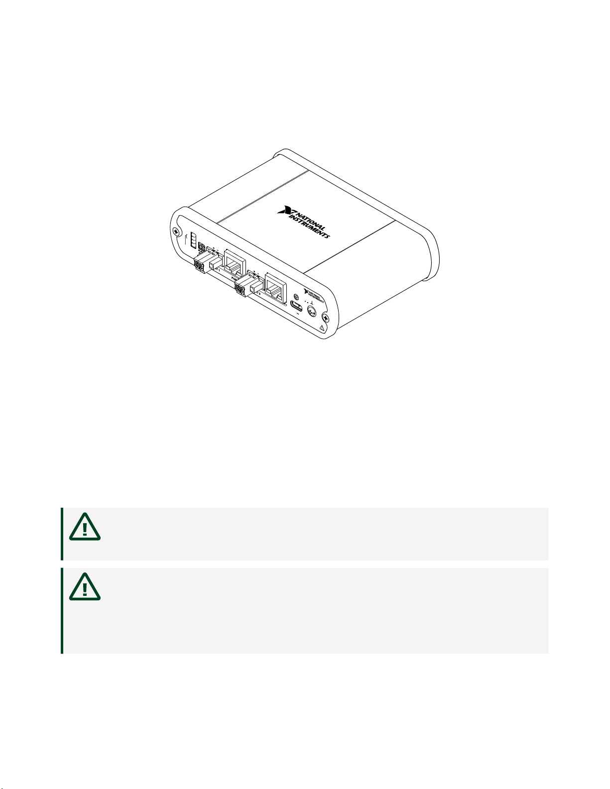
LEDs
LEDs on the le side of the front panel indicate Link and Activity on the 100BASE-T1
Automotive Ethernet ports. LEDs on the RJ45 connectors indicate Link, Activity, and
100 Mbit speed on the 100BASE-TX Ethernet ports.
LED LED State Behavior
POWER On Power on
O Power o
P1 LINK/ACT Steady Link established on port 1, no activity
Blinking Link established on port 1, activity present
O No link established on port 1
P3 LINK/ACT Steady Link established on port 3, no activity
Blinking Link established on port 3, activity present
O No link established on port 3
Port 2 LINK/ACT Steady Link established on port 2, no activity
Blinking Link established on port 2, activity present
O No link established on port 2
Port 2 100 Steady[1] 100 Mbit link speed selected on port 2
O[2] 10 Mbit speed selected on port 2
Port 4 LINK/ACT Steady Link established on port 4, no activity
Blinking Link established on port 4, activity present
O No link established on port 4
© National Instruments 7
IVN-8561 Getting Started

LED LED State Behavior
Port 4 100 Steady[1] 100 Mbit link speed selected on port 4
O[2] 10 Mbit speed selected on port 4
Table 1. LED Indicators
1 100 Mbit link speed is the defauilt setting. This LED will be on steady even when no
cable is attached.
2 10 Mbit link speed is not supported. If this LED is o, packets will not pass through.
Master/Slave Switches
Switches on the le side of the front panel control master/slave selection for the
100BASE-T1 Automotive Ethernet ports.
Switch Description Position
P1 MASTER/SLAVE 100BASE-T1 port 1 master/slave selection Up: Master mode selected
Down: Slave mode selected
P3 MASTER/SLAVE 100BASE-T1 port 3 master/slave selection
To establish a link between two 100BASE-T1 ports, one port must be configured as
master and the other as slave. The IVN-8561 allows you to establish a link with a port
in any configuration by selecting the appropriate mode with the front panel switch.
When you change the MASTER/SLAVE switch selection, the IVN-8561 immediately
changes the configuration and resets the corresponding 100BASE-T1 and 100BASE-
TX ports for that channel. The master/slave configuration of one channel can be
changed without aecting the other.
DIN Rail Mounting
The NI 9913 DIN rail mounting kit (part number 781740-01) contains one clip for
mounting the IVN-8561 on a standard 35 mm DIN rail. The four holes on the bottom
of the IVN-8561 allow the device to be mounted in multiple orientations.
Fasten the DIN rail clip to the IVN-8561 using two FLH #6-32 x 5/16" screws (included
in the kit) with a #2 Phillips screwdriver, as shown in the following figure.
ni.com
8
IVN-8561 Getting Started

Figure 1. DIN Rail Clip Installation
Clip the chassis onto the DIN rail with the larger lip of the DIN rail clip positioned up,
as shown in the following figure.
Figure 2. DIN Rail Clip Parts Locator Diagram
1
2
3
1. DIN Rail Clip
2. DIN Rail Spring
3. DIN Rail
Note Use only the screws provided in the DIN rail kit. Using longer screws
may damage the IVN-8561.
Wiring the IVN-8561
Terminal block headers are used to connect to the 100BASE-T1 ports. Compatible
plugs are included with the IVN-8561. Attach these plugs to twisted pair cabling to
connect a 100BASE-T1 network to ports 1 or 3 of the IVN-8561.
Pin Assignments
Refer to the following tables for descriptions of the terminal block (100BASE-T1) and
RJ45 (100BASE-TX) pin assignments.
Connector Pin Signal
1 100BASE-T1 Positive (+)
© National Instruments 9
IVN-8561 Getting Started

Connector Pin Signal
12
2 100BASE-T1 Negative (-)
Table 2. 100BASE-T1 Terminal Block Pin Assignments
Connector Pin Signal
1
2
3
4
5
6
7
8
1 Transmit+
2 Transmit-
3 Receive+
4 No Connection (NC)
5 NC
6 Receive-
7 NC
8 NC
Table 3. 100BASE-TX RJ45 Pin Assignments
Connecting the IVN-8561
Connect the IVN-8561.
1. Use twisted pair cable and the provided terminal blocks to connect your
100BASE-T1 network to ports 1 or 3 of the IVN-8561.
2. Use a Cat 5e Ethernet cable to connect 100BASE-TX network to ports 2 or 4 of
the IVN-8561.
Note 100 Mbit link speed must be selected for ports 2 and 4,
indicated by the LED next to the port.
3. Connect one end of the USB power cable to the IVN-8561, and connect the
other end to a standard USB 3.0 port.
4. Optionally, use the ground screw on the IVN-8561 to attach a ground cable.
ni.com
10
IVN-8561 Getting Started

Functional Diagram
100BASE-T1 is the standard for 100 Mbit/s Automotive Ethernet. The physical
connection consists of an unshielded twisted pair cable over which two connected
nodes transmit and receive simultaneously in point-to-point full-duplex operation.
The IVN-8561 provides two channels to convert data between 100BASE-TX Ethernet
and 100BASE-T1 Automotive Ethernet. Each channel consists of one port for
100BASE-T1 communication and one port for 100BASE-TX communication. The
IVN-8561 uses a two-position terminal block to connect a 100BASE-T1 Automotive
Ethernet system to the device.
Figure 3. IVN-8561 Connected to 100BASE-T1 and 100BASE-TX Networks
100BASE-T1
PHY
Terminal
Block
Port 1
100BASE-T1
PHY
100BASE-TX
PHY
100BASE-TX
PHY
Terminal
Block
Port 3
RJ-45
Connector
Port 2
RJ-45
Connector
Port 4
100 BASE-T1
Automotive Ethernet
100 BASE-TX
Ethernet
Where to Go Next
Hardware
SupportSupport
Services
ni.com/services
Located at ni.com/manuals
IVN-8561 Specifications
IVN-8561 Getting
Started Guide
Getting Started with
Automotive Ethernet
ni.com/info aegs
Automotive Ethernet
Software
ni.com/info aesw
Support
ni.com/support
NI Community
ni.com/community
Automotive Ethernet
LabVIEW Automotive
Ethernet Community
ni.com/info lvae
© National Instruments 11
IVN-8561 Getting Started

NI Services
Visit ni.com/support to find support resources including documentation,
downloads, and troubleshooting and application development self-help such as
tutorials and examples.
Visit ni.com/services to learn about NI service oerings such as calibration options,
repair, and replacement.
Visit ni.com/register to register your NI product. Product registration facilitates
technical support and ensures that you receive important information updates from
NI.
NI corporate headquarters is located at 11500 N Mopac Expwy, Austin, TX,
78759-3504, USA.
ni.com
12
IVN-8561 Getting Started
© 2022 National Instruments Corporation.
Other manuals for IVN-8561
1
Table of contents
Other National Instruments Media Converter manuals

National Instruments
National Instruments SCXI -1124 User manual

National Instruments
National Instruments NI 6221 User manual

National Instruments
National Instruments NI GPIB-RS232 User manual

National Instruments
National Instruments GPIB-422CV User manual

National Instruments
National Instruments GPIB-PRL User manual

National Instruments
National Instruments GPIB-232CV User manual

National Instruments
National Instruments NI PXIe-5601 Manual

National Instruments
National Instruments NI PXI-5600 User manual

National Instruments
National Instruments IVN-8561 User manual

National Instruments
National Instruments GPIB-232CV-A User manual