National Luna NLDC-25 User manual


Index
Introduction
Safety Information
External features
Preparing for Installation
Fitting the NLDC-25
Universal Mounting Fixture
Typical Installation diagram
Installation steps
Selecting battery type
Ignition over-ride
Temperature compensation
Remote monitor
Remote monitor operation
Remote monitor warning messages
Application examples
Specifications
1
1
2
3
3
4
6
7
7
8
8
9
10
11
12
15

SAFETY INFORMATION :
ŸBefore installation, read the instructions carefully.
ŸBefore installation, disconnect any existing batteries.
ŸThe NLDC-25 is used for charging 12V lead-acid and automotive Lithium batteries only.
ŸDo not use for any purpose other than battery charging.
ŸDo not attempt to power any devices or instruments directly using the output of NLDC-25.
ŸDo not attempt to charge a non-rechargeable or battery other than 12V.
ŸNever attempt to charge a damaged battery or leaking battery.
ŸAvoid open flames in the vicinity of the battery.
ŸBattery acid is highly corrosive. If your skin or eyes come into contact with acid, immediately rinse
the affected area with water and seek medical advice.
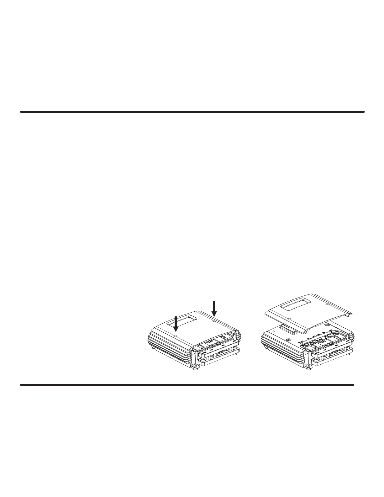
ŸDo not alter or disassemble the NLDC-25 under any circumstances.
ŸUnauthorized disassembly, repairs or modifications will void any warranty.
ŸAttempts to use the NLDC-25 for purposes other than indicated in this manual will void the warranty.
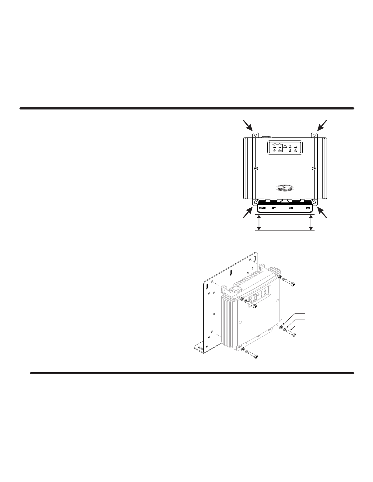
ŸEnsure all connections are secure and cables are installed in a safe manner.
ŸUse the correct cabling size and fuses in accordance with the installation instructions.
The NLDC-25 from National Luna is a DC to DC battery charger and isolator for a dual-battery system.
It will charge an auxiliary or service battery from a vehicle alternator or Solar panel up to 25A output current.
Traditional 12V and 24V vehicle alternators as well as variable voltage alternators are supported.
The integrated MPPT solar regulator provides a maximum output power of 375W but can support solar panels higher than this.
Solar panel voltages up to 42V can be connected.
The NLDC-25 features a 6-stage charge algorithm that is suitable for any Lead-Acid battery type as well as automotive Lithium-Ion batteries.
3 safety stages analyse the battery and can detect batteries that are damaged and unable to accept charge.
Temperature compensation is used to optimise the output voltage, ensuring safe and full battery charging under various conditions.
The NLDC-25 supports the connection of a remote monitor that displays information about the system and battery levels to the user on a
high-contrast LCD screen.
The NLDC-25 has a IP67 rating for harsh environments and is protected against reverse-polarity, over-voltage, over-temperature and
over-current conditions.
NLDC-25 Dual Battery Isolator and Charger
1

NLDC-25 External features
1 - NL-DC25 Metal Base
2 - Remote monitor connecting port
3 - Status display
4 - Removable top cover
5 - Temperature compensation input
6 - Ignition over-ride input
7 - Removable terminal block
8 - Terminal block - Auxiliary battery output
9 - Terminal block - Common ground connections
10 - Terminal block - Alternator input
11 - Terminal block - SOLAR panel input
12 - Mounting feet
Status Display
1 - Battery type selection button
2 - Battery type indicator
3 - OK / Fault indicator : Green = OK, Red = Fault
4 - Input source indicator (ALT or SOLAR)
5 - Charge stage indicator
NLDC-25 Features
1
3
2
4
DC-DC Battery Charger
Battery
Float
Li-ion Wet
Ca+ AGM/Gel
Charge
OK /
342 5
2
1
5
6
7
8
9
10
11
12

ŸThe NLDC-25 should be located close to the auxiliary battery for best voltage regulation.
ŸThe NLDC-25 can operate in harsh environments but it is best installed in a location that is cooler with adequate ventilation.
ŸAvoid areas exposed to harsh or corrosive chemicals, excessive dust, extreme heat or mechanical movement.
ŸThe NLDC-25 can be installed vertically or horizontally.
ŸDo not block or obstruct the cooling fins on the NLDC-25.
ŸAllow clearance around the NLDC-25 for cables and ventilation.
ŸIt is normal for the NLDC-25 to get hot during operation, keep any objects that are heat-sensitive away from the NLDC-25.
ŸIf the temperature compensation probe is used, it must be able to reach the auxiliary battery.
2
ŸIt is recommended to use 16mm cables for connections to the main and auxiliary batteries. Smaller gauge cables can be used for short
distances.
ŸIn-line fuses must be fitted in the positive cables close to the respective main and auxiliary batteries.
ŸUse the common ground connections on the terminal block for all negative cable connections.
ŸUse appropriate cable lugs for the cable size used.
Preparing for Installation
Removing the top cover
3
In order to select the battery type and to install the
temperature compensation & ignition over-ride
wires, the top cover will need to be removed.
Loosen the two screws as indicated in order to
release the cover.

Fitting the NLDC-25
4
The NLDC-25 has 4 mounting feet, use these to attach the NLDC-25 to a secure,
flat surface.
Use appropriate screws or bolts to attach the NLDC-25 securely, M4 machine bolts
are recommended.
DO NOT drill into or modify the NLDC-25 housing.
Allow enough clearance for power cables to connect to the terminal block.
50mm or more is recommended.
It is recommended to secure cables together and prevent excessive movement
in the final application.
If the remote monitor is fitted, allow clearance for the plug and cable.
The NLDC-25 is supplied with a universal mounting fixture
and fasteners that can be used to aid installation in a variety of
applications.
This fixture allows the NLDC-25 to be attached in several ways
depending on the application requirements.
Use the supplied screws and washers to secure the NLDC-25 to the
plate in the chosen orientation.
Secure the fixture in the final application with appropriate fasteners.
Universal mounting fixture
M4x20 screws
Spring washer
Flat washer
Cable Clearance

5
The supplied step-plates can be used to raise the NLDC-25
above obstructions such as pipes or cables if necessary.
Use the supplied screws and washers to assemble the fixture
as shown in the diagram.
Use appropriate fasteners to secure the assembled plate
to the application.
The NLDC-25 can be rotated on the plate by 90° to suite the
application.
Vertical or horizontal installation is supported.
Step plates
M4x20 screws
Spring washer
Flat washer

Typical Installation
FUSE FUSE
SOLAR PANELS
+
-
+
-
AUX
BATTERY
MAIN
BATTERY
6
+
-

Installation Steps
Selecting Battery Type
The NLDC-25 will optimise charge voltage based on the selected battery
type.
Remove the NLDC-25 top cover to access the battery select button.
The battery type can be selected by pressing the “Battery” button on the
NLDC-25 control panel. The chosen battery type is displayed.
ŸDisconnect the main battery before starting installation.
ŸInstall the NLDC-25 using the mounting feet. (Described on page 4).
ŸInstall positive and negative cables from the Auxiliary battery to the NLDC-25. Connect to the AUX and GND terminals respectively.
ŸInstall one in-line fuse on the positive cable near to the Auxiliary battery. Do not connect the battery yet.
ŸInstall positive and negative cables from the NLDC-25 to the Main battery. Connect to the ALT and GND terminals respectively.
ŸInstall one in-line fuse on the positive cable near to the Main battery.
ŸIf a solar panel is used, connect the positive and negative cables from the solar panel to the SOLAR and GND terminals respectively.
ŸConnect the temperature compensation probe and IGN over-ride cable if used. (See page 8).
ŸInstall the remote monitor (if used) and run its cable to the remote monitor port on the NLDC-25. (See page 9).
ŸDouble check all cables and connections for correct installation.
ŸRe-connect the Main battery. The NLDC-25 should now be powered and will show status on the status display.
ŸSelect the Auxiliary battery type. See “Selecting Battery Type” below.
ŸConnect the Auxiliary battery.
ŸIf the remote monitor is installed, the voltages of the Main and Auxiliary batteries will now be displayed.
ŸThe system is now ready.
Wet
AGM / Gel
Ca+
Li-ion Used for automotive Lithium-ion or LiFe
batteries.
Used for regular automotive starting
and flooded high-cycle batteries.
Used for flooded deep-cycle, calcium and
maintenance - free batteries.
Used for all types of AGM and Gel
batteries.
For safety reasons, the battery type cannot be changed if the
AUX battery is already connected.
7

The ignition (IGN) over-ride input can be used in vehicles that have
variable alternator output.
This is common with “Smart” alternators.
Connect the IGN terminal using a small gauge wire to a 12V
ignition lead or source in the vehicle.
This source must be switched to a positive voltage when the
vehicle is started and switched off when the vehicle is turned off.
If the IGN feature is used, the Turn-ON and Turn-OFF voltages of
the NLDC-25 are adjusted (See specifications on page 15).
IGN over-ride Temperature sensor
The NLDC-25 is supplied with a temperature compensation probe.
For best performance, connect the probe end to one of the AUX
battery terminals or to the battery casing.
Connect the smaller ring on the sensor cable to the “sensor” terminal
on the NLDC-25. Connect the larger ring to one of the GND terminals.
With the probe fitted, the NLDC-25 will optimise final charge voltage
based on the measured temperature. This prevents over-charge at
higher temperatures and increases charge performance at lower
temperatures.
For safety, charge is stopped if the battery temperature increases
above 50°C.
Fitting the temperature probe in a location other than on the
AUX battery can increase the risk of battery over or
under-charging.
CAUTION - DO NOT connect the IGN over-ride permanently
to a non-switched positive source.
Doing so may result in excessive drain on the Main battery.
8
+
-
AUX
BATTERY
+
-
MAIN
BATTERY
Temperature sensor
Ignition

Remote monitor - (Optional accessory)
Connecting the Remote monitor
The Remote Monitor for the NLDC-25 provides status information about the system and
batteries on a high-contrast LCD screen.
Information such as Main and Auxiliary battery voltages, charge mode, charge current,
battery type, battery temperature and error conditions are displayed on a choice of 3
user-selectable display modes.
In addition to the selectable screen modes, the user is able to increase or decrease the
screen brightness and choose to turn the display on or off.
The screen will turn off automatically when the system is idle.
It will turn on automatically when the next charge cycle starts.
The Remote Monitor is supplied with a mounting bracket
that allows the viewing angle to be adjusted.
Attach the bracket to a flat surface using appropriate
screws or adhesive.
Slide the Remote Monitor onto the mounting bracket until
it clicks securely.
Connect the square end of the supplied data cable to the
NLDC-25 remote port, it can fit in one direction only (fig 1).
Press the plug until it clicks securely and forms a
waterproof seal.
Connect the flat end of the data cable to the Remote
Monitor. (fig 2).
This connector can fit both ways.
Fig 1 Fig 2
Power
Screen mode
Brightness UP
Brightness DOWN
9

Remote display operation
Display mode 1 - This mode focuses on the auxiliary battery with the majority of the screen used to
show the auxiliary battery voltage and temperature (if probe is installed).
The input source (ALT or SOLAR) as well as charge current is displayed during a charge cycle.
If SOLAR is the active charge source, the solar panel voltage is displayed.
If there are no active charge cycles, “STBY” is displayed.
The remote monitor can be turned ON or OFF by pressing the POWER button.
The display will turn off automatically after a short delay if there is no active charge cycle.
The display brightness can be increased or decreased by pressing the UP or DOWN buttons.
Display mode 2 - In this mode, the status of the main and auxiliary batteries are represented as
graphical bar-graphs. The actual voltages are shown for the respective batteries.
During a charge cycle, the input source (ALT or SOLAR) is displayed with the actual charge current.
If there is no active charge cycle, “STANDBY” is displayed.
The AUX graph is animated during charge and represents the battery state of charge.
Display mode 3 - This mode shows voltages of the respective main and auxiliary batteries as well as
charger mode, charge current, battery type and battery temperature (if probe is installed).
If there are no active charge cycles, “STBY” is displayed.
The remote monitor has 3 display modes that represent the status of the charging system in different ways.
Press the MODE button to cycle through the different display options.
10

The remote monitor will respond and indicate various error conditions that may occur under normal operation.
These warnings should be investigated to prevent damage to the batteries or the NLDC-25 system.
The following symbols or messages may appear on any of the 3 display modes :
Warning Messages
LOW BATTERY or NO BATTERY - This symbol is displayed when either the Main or Auxiliary battery voltage is lower than 11.4V
or there is no connection to one of the batteries. Check fuses and connections to both batteries.
If this symbol and voltage display are flashing, the battery is not holding charge and should be tested.
OVER VOLTAGE PROTECTION - The voltage applied to the SOLAR, ALT or AUX terminals is too high.
Ensure the application voltages are within specification.
OVER TEMPERATURE PROTECTION - The detected auxiliary battery temperature is above 50°C. Charging is stopped to
prevent damage to the battery. It is possible that the battery is damaged or is located in an area that is too hot.
This error will also be displayed if the NLDC-25 temperature is above 115°C. Charge will stop until the system temperature drops
to a safe level.
OVER CURRENT PROTECTION - The detected charge current is higher than specification.
Inspect the installation for cable faults or short-circuits.
REVERSE POLARITY - The connections to the auxiliary battery have been reversed.
Check the battery connections.
BAD BATTERY - The NLDC-25 has detected that the AUX battery is not able to be charged safely.
Test the battery and replace if necessary.
OVP -
OTP -
OCP -
REV -
BAD -
11

The NLDC-25 can be installed in a Trailer or Caravan that is equipped
with batteries.
In this application, the NLDC-25 supports a stand-alone application with
solar input as well as a removable connection to the towing vehicle’s main
battery.
More than one solar panel can be connected.
(See specifications on page 15).
The NLDC-25 will support multiple auxiliary batteries connected in parallel
to form a large 12V bank.
This is a common configuration in trailers or caravans with large service
battery banks.
Care should be taken to ensure that the parallel batteries are matched in
type, capacity and age.
Application examples
+
-
AUX
BATTERY
+
-
AUX
BATTERY
+
-
AUX
BATTERY
+
-
MAIN
BATTERY
Connector to
MAIN battery
FUSE
FUSE
FUSE
Installation in a Trailer or Caravan
Multiple Auxiliary batteries
12
+
-

Application examples
The NLDC-25 directly supports vehicles with 24V alternators. Usually
these vehicles have two 12V main batteries connected in series.
The output of the NLDC-25 will charge a 12V battery or battery bank.
This is useful when 12V accessories are used in a vehicle with a 24V
electrical system.
13
+
-
MAIN
BATTERY
+
-
MAIN
BATTERY
+
-
MAIN
BATTERY
+
-
AUX
BATTERY
+
-
AUX
BATTERY
12V 24V
FUSE FUSE
FUSE FUSE
In cases where the auxiliary battery has had insufficient charging time,
a mains-powered battery charger can be connected to the auxiliary
battery.
It is not necessary to disconnect the NLDC-25, provided that there is no
active charge cycle and the NLDC-25 is in standby mode.
Do not connect an external battery charger if power is being delivered
from a solar panel or the vehicle alternator is running.
Connecting an external battery charger.
24V vehicles.
+
-
Battery
Charger
AC

Application examples
14
Connector to
MAIN battery
+
-
Auxiliary Battery Box
The NLDC-25 can be directly connected to the input of a National Luna Auxiliary Battery Box or other 12V battery pack.
Any loads connected to the battery will be powered by the NLDC-25 when a charge cycle is active.
If the Auxiliary Battery Box is disconnected, the NLDC-25 will automatically revert to a safe mode. An error will appear on the
remote monitor, if installed (see page 11).
Connecting an external battery pack
+
-

Technical Specifications
15
Voltage Range
Alternator
Solar
Solar Regulator
Type
Output Current
Output Power
12V Alternator Input
Turn ON
Turn OFF
Over-Voltage
24V Alternator Input
Turn ON
Turn OFF
Over-Voltage
Ignion Over-ride
Turn ON
Turn OFF
Over-Voltage
Output
Voltage
Current
Power
Operang Temperature
Standby Current
Ingress Protecon
Standards
Dimensions
Remote Display
Baery Types Bulk Voltage Float Voltage
AGM / Gel 14.4V 13.6V
Standard Wet 14.6V 13.6V
Calcium 14.8V 13.6V
Lithium Ion 14.4V 13.6V
9V - 42V
11V - 32V
13.2V
12.6V
MPPT
375W
25A
14.8V - 16V
-20°C to 85°C
IP67
EN55011, AS/NZS CISPR11
11.0V
> 31V
3V -14.8V
25A
375W
26.4V
23.2V
29.6V - 31V
12.0V
158mm x 115mm x 53mm
Oponal
< 10mA
Baery Temperature Compensaon
High temperature
Low Temperature
Baery over-temperature protecon
Device Protecon
Reverse Polarity
Over Voltage
Over Current
Bad Baery Detect
-17mV per °C above 30°C
+17mV per °C below 21°C
50°C
Over Temperature
Charge Algorithm
Voltage
Diagnosis Recovery Bulk Absorption Analysis Float
Current
Step 1 2 3 4 5 6

Technical Specifications - continued
158mm
126mm
196mm - 206mm
216mm - 226mm
149mm
180mm
53mm
110mm 65mm
155mm
65mm 37mm
16
38mm 39mm 38mm


Table of contents
Other National Luna Batteries Charger manuals
Popular Batteries Charger manuals by other brands

Crosscall
Crosscall X-CABLE instruction manual

TECNO2
TECNO2 Energa C14-5-AY Instruction, use and maintenance manual

ProMariner
ProMariner ProMar1 5 Owner's manual and installation guide

VOLTCRAFT
VOLTCRAFT CHARGE MANAGER 2020 operating instructions

Karlik
Karlik MCUSBBO-8 user manual

Bebob
Bebob VS2MICRO user manual