National Nail CAMO DECK RESPONSIBLY DRIVE User manual

1REV. 8/19/19
OWNER’S MANUAL
(616) 538-8000
CAMOFASTENERS.COM
NATIONAL
NAIL
DECK RESPONSIBLY ™
CAMO®
D
RIVE™
ENGLISH

2
WELCOME TO CAMO®
Congratulations on purchasing the CAMO®DRIVE™. You have
selected a brand you can count on to deliver best practice
installation, and perform job after job. Please take the time to
read and understand the information contained in this Owner’s
Manual before operating the CAMO®DRIVE™.
The CAMO®DRIVE™is a versatile tool that enables you to Edge,
Clip, or Face fastening wood, composite, or PVC deck boards to
the deck substructure. Improper use of the CAMO®DRIVE™could
result in serious injury.

3
TABLE OF CONTENTS
IMPORTANT INFORMATION......................................................... 4
TOOL SPECIFICATIONS ................................................................. 5
ASSEMBLING THE CAMO®DRIVE™............................................. 6
LOADING THE FASTENERS.......................................................... 7
FASTENER INSTALLATION ........................................................... 9
CAMO®DRIVE™PARTS LIST.......................................................... 12
WARRANTY ........................................................................................ 13

4
The following terms will apply interchangeably throughout this Owner’s Manual:
Driver Drill / the Drill
Attachment / CAMO®DRIVE™
Tool – refers to CAMO®DRIVE™assembled with driver drill
PERSONAL SAFETY ITEMS
• Do not use the Tool and/or components prior to reading the CAMO®DRIVE™Owner’s Manual.
• Always wear eye protection that conforms to ANSI requirements (Z87.1) and provides protection against flying particles
both from the front and side. Eye protection should be worn by the operator and by others in the work area. Eye
protection is required to protect against flying fasteners and debris that could possibly cause severe eye injury.
• The user is responsible to enforce the use of eye protection equipment by the Tool operator and all other personnel in the
work area.
• To prevent accidental injuries: Handle the Tool and components with care - Always assume that the Tool contains
fasteners - Always disconnect the power from the Driver Drill when:
• Loading CAMO®Collated Fasteners for DRIVE
• Performing inspection, maintenance or repair
• Clearing a screw jam
• The Tool is not in use
• Leaving the work area
• Moving the Tool to another work location
• Handing the Tool to another person
• Storing the Tool - To reduce the risk of electric shock and damage to the Tool, never immerse the Tool in liquid or
allow a liquid to flow inside the Tool - Never point the Tool toward yourself or anyone else - Never engage in
horseplay - Never hold or carry the Tool with a finger on the trigger of the drill. - Never place a hand or any other
part of the body in the fastener discharge area of the attachment while the power is connected.
OPERATION OF THE TOOL
• Never inspect, maintain, repair, adjust, clear a jam or store the Tool with the power connected.
• Never use the Tool in proximity of flammable gases or liquids, as some tools will create sparks that can be an ignition
source for a fire or explosion.
• Never assume the Tool is empty of fasteners.
• Never point the Tool toward yourself or any other persons.
• Never drive the Tool unless it is in contact with the work-piece.
• Never use the Tool as a hammer or wedging device or drop to the floor from any height.
• Use only CAMO®Collated Fasteners with the DRIVE™. Never use any fasteners that are not specified for use with this
Attachment. The DRIVE™holds one (1) strip of 50 CAMO®Collated Fasteners.
IMPORTANT INFORMATION
TERMINOLOGY

5
CAMO®Collated Fasteners, CAMO®Tools and CAMO®Driver Bits are engineered to work exclusively together. Using other
branded tools, fasteners or bits will impair performance and not produce the desired results.
The CAMO®DRIVE™utilizes a Driver Drill (not included).
TOOL SPECIFICATIONS
CHUCK
DRIVE SHAFT
HANDLE
TOOL BODY
BIT CHANGE
RELEASE BUTTON
FACE GUIDE EDGE GUIDE
CLIP GUIDE
RETRACTING PICKER
DEPTH SET DIAL
SCREW CHANNEL

6
USING THE CAMO®DRIVE™
INSTALLING THE DRIVER BITS
INSTALLING THE HANDLE
DETERMINING IF YOU WILL USE EDGE, CLIP, OR FACE FASTENING
The DRIVE™can be set up for left or right hand use.
You will need one of the two included bits and guides for your installation.
Use a bit to depress the release
button in the channel.
The handle is attached to the tool
body screwing it onto the bolt
found installed at the top of the
tool body.
• For Edge fastening you will install a CAMO®T-15 driver bit and the Edge guide.
• For Clip fastening, you will install a CAMO T-15 driver bit and the Clip guide.
• For Face (top down) fastening you will need to install the CAMO®T-20 bit and the Face guide.
You can reverse the handle set up
by simply loosening the bolt and
re-installing it to the other side of
the tool body.
As you depress the release
button, remove the lower body
of the tool.
Replace the lower tool body – it
will click into place.
Pull the chuck back to allow the
bit to pull free and install the new
bit.

7
CHANGING THE GUIDE
Depress the thumb release
button.
Pull the guide free from tool. Insert new guide paying attention
to the direction of the alignment
tabs.
Always remove the collation strip before removing the guide.
LOADING SCREW STRIPS
Be sure that you have the correct bit size inserted for the fastener that you are driving! The CAMO®DRIVE™has both necessary
bit sizes include in the package.
Edge: T15 Clip: T15 Face: T20
Insertion end of screw strip has
arrows
Hold body of the tool with one
hand so that screws stay in place
Slide strip into screw strip channel
Slide picker up to nose of the tool
and fold the open strip onto the
picker teeth with your pointer
finger
Slide collation strip up and
through the nose of the tool until
it will go no further
Caution! Be very careful not to let
go of the picker as it will recoil
very quickly and could damage
the tool when it strikes the stop.
Make sure the strip is firmly
hooked to the picker teeth.

8
ATTACHING YOUR DRIVER DRILL
UNLOADING SCREW STRIPS
CAMO®DRIVE™is able to be used with either a tightening chuck or a locking chuck.
Slowly return the picker to the
bottom of tool. Caution! Be very
careful not to let go of the picker
as it will recoil very quickly and
could damage the tool when it
strikes the stop.
To unload the installed strip of
screws, slide the picker up to the
nose of tool where strip was first
attached. This will release the
tension and the strip should pop
free of the picker teeth.
To attach to a tightening chuck,
simply insert the large collar of
the drive shaft into the drill chuck
and tighten
Take an extra CAMO®DRIVE™
bit and insert into the end of the
collar
TO ATTACH CAMO®DRIVE™TO A LOCKING CHUCK
TO ATTACH CAMO®DRIVE™TO A TIGHTENING CHUCK
Attach your driver drill’s locking
chuck to the smaller bit
Make sure the drive shaft is securely tightened before driving screws

9
Before beginning installation of your deck, you will need the following:
• CAMO®DRIVE™Tool
• CAMO®Collated Fasteners
• Driver Drill (Corded or cordless)
• Optional: Secondary Spacers if a gap is desired
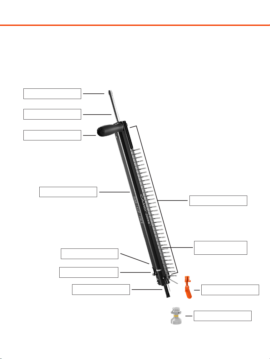
DRIVE tool setup:
• Make sure you have a T15 DRIVE bit installed in the DRIVE tool. The T15 bit is identified with a yellow and orange color
band on the bit.
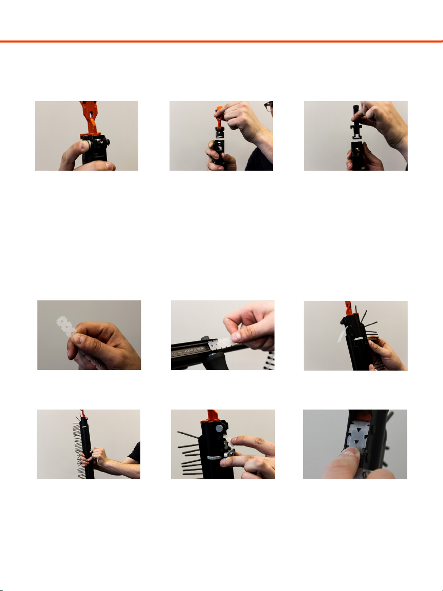
• Attach the edge guide on the DRIVE tool (see changing the guide section on page 7).
• Drill clutch setting: If your driver drill has a clutch setting it should be in “drill or maximum torque” setting position.
FASTENER INSTALLATION - EDGE SCREW
Edge Screw Fastening with the DRIVE™enables you to install a beautiful fastener-free deck surface at an incomparable speed.
Engineered for no gap installation of treated lumber. If gapped installation is desired, use secondary spacers.
Gap Options:
The CAMO®DRIVE™allows for multiple gap options when installing deck boards. For wet treated lumber, the zero gap option
allows builders to butt deck boards tightly together. If a gap is desired, secondary spacers may be used between the boards.
Board Installation:
To begin deck installation, lay the first board that abuts the structure into position. Starting with the outside edge of the board,
fasten the deck board at each joist using the CAMO®DRIVE™as follows:
For the outer board end of the deck board, align the Edge Guide with the joist below the deck board (a minimum of 1’’ from
board ends). Place the nose of the DRIVE™tool so that the Edge Guide is flat to the board surface, with the Edge Guide tight to
the board edge.
Using the Tool Handle, apply downward pressure to make sure that the nose stays firmly in position with the board edge
throughout the drive process.
While maintaining positive pressure on the DRIVE™tool, push the Driver Drill down to engage the bit and screw. Depress the
drill trigger and, running the drill at full RPM, drive the screw applying pressure throughout. DO NOT FORCE THE SCREW. Allow
the Edge screw to spin and auger the surface. After a moment, the screw will grab and pull into the board. The drill and tool
will be fully compressed when the screw is fully seated. When driven fully and correctly, the finished position of the Edge screw
should be just below the surface of the edge. It should not protrude from the side of the board. (Adjust if necessary.)
Once the fastener is driven, retract the driver drill fully allowing the next screw to be pulled into place for driving. The next
fastener will automatically be loaded into drive position. Repeat down the length of the board.
Place the next deck board in position and push tight to the board abutting the structure. Repeat process above.
For the inside edge of the deck board, align the Edge Guide with the joist below the deck board, positioning the Edge Guide
between the two adjoining deck boards. Make sure that the Edge Guide is parallel with the surface of the deck board and
the Edge Guide is firmly against the radius of the edge of the deck board. Maintain firm pressure against the deck board
throughout the drive process.
Repeat down the length of the board until the board is secured at every joist and both sides of the board.. Do not skip any
joists. Repeat for remaining deck boards.
Visit www.camofasteners.com/videos for video instructions.

10
FASTENER INSTALLATION - EDGECLIP & EDGEXCLIP
DRIVE tool setup:
• Make sure you have a T15 DRIVE bit installed in the DRIVE tool. The T15 bit is identified with a yellow and orange color
band on the bit.
• ATTENTION! ONLY USE THE COLOR-CODED DRIVE BIT - BIT INCLUDED IN THE EDGECLIP OR
EDGEXCLIP PAILS IS FOR HAND DRIVE
• Attach the clip guide on the DRIVE tool (see changing the guide section on page 7).
• It is not necessary to load any screws into the DRIVE tool as the EdgeClips and EdgeXClips come pre-assembled.
• Drill clutch setting: If your drill has a clutch setting please start by setting the clutch to a medium low setting (30% of
maximum torque). Drive tool should drive the screw and snugly tighten down the board. If that torque setting is not
sucient to allow the screw to be driven completely, slightly increase the torque until the the screws securely tighten the
clip in place. Excessive torque can cause over-driving resulting screw spin-out or stripping.
Board Installation:
Once your starter board is fastened in place you are ready to begin installing the rest of your deck with EdgeClip or EdgeXClip
using the DRIVE tool.
Follow the Clip installation instructions included with your EdgeClip or EdgeXClip for instruction on placing the clips in the
groove of the decking.
Once your clips are set between the deck boards, you can now use the DRIVE tool to tighten down all of the clips securing your
decking.
• Place the Clip Guide installed on your DRIVE tool over the screw
• Depress the drill trigger running at full RPM and apply downward pressure
• The Clip Guide will direct the DRIVE bit engaging the head of the screw and securing the clip in place
Visit camofasteners.com/videos for video instructions.

11
Face Screw Fastening with the DRIVE™allows you to face screw deck boards down using CAMO®collated face wood screws
and CAMO®color matched composite screws.
DRIVE tool setup:
• Make sure you have a T20 DRIVE bit installed in the DRIVE tool. The T20 bit is identified with a black color band on the
bit.
• Attach the clip guide on the DRIVE tool (see changing the guide section on page 7).
• Drill clutch setting: If your driver drill has a clutch setting it should be in “drill or maximum torque” setting position.
Gap Options:
The CAMO®DRIVE™allows for multiple gap options when installing deck boards. For wet treated lumber, the zero gap option
allows builders to butt deck boards tightly together. If a gap is desired, secondary spacers may be used between the boards.
Board Installation:
Be sure that you have the correct bit size inserted for the fastener that you are driving! The DRIVE™has both of the necessary
bit sizes include in the package.
Screw Drive Depth:
Utilizing the Depth dial on the tool, you can adjust the depth of drive to your preference.
To begin deck board installation, lay the first board into position. Fasten the deck board with 2 screws at each joist using the
CAMO®DRIVE™as follows:
Using the Tool Handle, apply downward pressure to make sure that the nose stays firmly in position with the board throughout
the drive process.
While maintaining positive pressure on the DRIVE™tool, push the Driver Drill down to engage the bit and screw. Depress the
drill trigger and, running the drill at full RPM, drive the screw applying pressure throughout. The screw will be fully driven once
the driver drill and tool are full compressed.
Once the fastener is driven, retract the driver drill fully allowing the next screw to be pulled into place for driving. The next
fastener will automatically be loaded into drive position.
Repeat down the length of the board until the entire plank is installed. Do not skip any joists.
Visit www.camofasteners.com/videos for video instructions.
FASTENER INSTALLATION - FACE SCREW

12
PARTS LIST
HANDLE KIT
UPPER BODY
ASSEMBLY
CLUTCH ASY
DRIVE BIT
LOWER BODY
ASSEMBLY
DRIVE SHAFT
DRIVE BIT
EDGE GUIDE
FACE GUIDE
CLIP GUIDE
INCLUDES HANDLE,
BOLT, JAM NUT
REPLACEMENTS
SOLD SEPARATELY
REPLACEMENTS
SOLD SEPARATELY
REPLACEMENTS
SOLD SEPARATELY
REPLACEMENTS
SOLD SEPARATELY
REPLACEMENTS
SOLD SEPARATELY
20181015
REV:
CAMO DRIVE SCHEMATIC

13
LIMITED WARRANTY FOR CAMO®DRIVE™
National Nail Corp. (“NNC”) warrants to the original purchaser (“Buyer”) for a period of one year from delivery of the goods
to the Buyer that all goods manufactured solely by NNC (“Products”) will be free from substantial defects in material or
workmanship under normal and intended use and service. The Products shall not be defective to the extent that they are
damaged due to the method or length of storage, negligence, misuse, or alteration by Buyer. This Limited Warranty sets forth
Buyer’s sole and exclusive remedies for any defect in the Products. Buyer acknowledges that NNC may provide additional
goods with the Products that are not manufactured by NNC, including, without limitation, the Driver Drill. This Limited Warranty
does not apply to such goods and Buyer’s sole recourse for a defect in such goods will be the original manufacturer of such
goods.
This Warranty does not cover normal wear and tear or any Products that were: (1) purchased other than from an authorized
NNC dealer, retailer or distributor; (2) modified or altered by anyone other than NNC; (3) used with any fasteners or accessories
other than fasteners and accessories approved by NNC; (4) improperly serviced; or (5) subject to negligence, excessive uses,
or any use not in accordance with the printed materials provided with the Products, all as determined by NNC in its sole
discretion.
If there is a defect in any Products constituting a breach of this warranty, NNC will at its option either repair or replace such
Product. NNC will not pay for any of Buyer’s shipping or labor costs or charges for correcting defects or making additions nor
will NNC accept any returned Products unless the correction or return is authorized in advance by NNC in writing. NNC shall
furnish to Buyer instructions for the disposition of the defective Products. NNC shall have the option of requiring the return
of the defective Products and proof that the Products were not used or altered or subject to misuse or abuse to establish the
claim. The acceptance of any Products returned to NNC shall not be deemed an admission that the Products are defective or
in breach of this warranty, and if NNC determines that the Products are not defective they may be returned to Buyer at Buyer’s
expense.
The rights and obligation under this Limited Warranty may not be assigned or delegated to a third party by you without
the prior written permission of NNC. The Limited Warranty provided to you will be void if you have not paid in full for all
the Products or if you are past due on any amount due to NNC. Neither you nor any other person may modify or expand
the warranty provided herein, waive any of the limitations, or make any dierent or additional warranties with respect to
the Products. Any statements to the contrary are hereby rendered null and void unless expressly agreed to in writing by an
authorized ocer of NNC.
EXCEPT AS STATED ABOVE, NNC DOES NOT MAKE ANY WARRANTY AS TO THE PRODUCTS AND, IN PARTICULAR, DOES
NOT MAKE ANY WARRANTY OF MERCHANT-ABILITY OR FITNESS FOR ANY PARTICULAR PURPOSE, AND YOU ARE SOLELY
RESPONSIBLE FOR DETERMINING THE PROPER APPLICATION AND USE OF THE PRODUCTS.
NNC SHALL NOT HAVE ANY TORT LIABILITY TO YOU OR ANY OTHER PERSON WITH RESPECT TO ANY OF THE PRODUCTS
AND SHALL NOT BE LIABLE FOR CONSEQUENTIAL, INCIDENTAL, SPECIAL, EXEMPLARY, INDIRECT OR PUNITIVE DAMAGES
ARISING FROM ANY PRODUCT DEFECT, DELAY, NONDELIVERY, RECALL, OR OTHER BREACH.

14
Table of contents