National Railway Supply NRS-24 Service manual

www.nationalrailwaysupply.com
1-800-357-3572 1 01546G
NATIONAL
RAILWAY
SUPPLY
Installing, Operating and
Service Instructions for the
NRS-24/30 Solid State Charger
MODEL NRS-24/30 BATTERY CHARGER
PLEASE SAVE THESE IMPORTANT SAFETY AND OPERATING INSTRUCTIONS
For correct operation of the equipment, it is important to read and be familiar
with this entire manual before installing and operating the charger.
DO NOT DISCARD THIS MANUAL AFTER READING.
LOOK FOR THIS SYMBOL TO POINT OUT SAFETY PRECAUTIONS. IT MEANS:
BECOME ALERT—YOUR SAFETY IS INVOLVED. IF YOU DO NOT FOLLOW THESE
SAFETY INSTRUCTIONS, INJURY OR PROPERTY DAMAGE CAN OCCUR.
1. IMPORTANT SAFETY INSTRUCTIONS
a. Before using the battery charger, read all
the instructions and caution markings on the
battery charger, the battery, and all of the
products using the battery.
b. Do not touch the uninsulated parts of the AC
input or the DC wires, the charger's binding
posts, or the battery terminals as there is a
possibility of electrical shock.
c. Batteries produce hydrogen gas while
operating, which can explode if ignited.
Never smoke, use an open flame, or create
sparks in the vicinity of the battery. Ventilate
the area well when the battery is charging in
an enclosed area.
d. Batteries contain caustic material which may
cause burns. Do not get in eyes, on skin, or
clothing. If the gelled or liquid content of the
batteries contacts the skin or clothing, wash
the area thoroughly with water. In the case
of contact with the eyes, flush immediately
with clean water for 15 minutes and obtain
medical attention.
e. Connect or disconnect the battery plug only
when the charger output is off to prevent
arcing or burning.
f. Only qualified personnel should program or
service this equipment.
g. De-energize all AC and DC power
connections before servicing this unit. If
injury does occur, apply standard treatment
for electrical shock and, if necessary,
consult with a physician.
h. The charger is not for outdoor use. Do not
expose the charger to rain or snow.
i. Do not operate the charger if it has received
a sharp blow, been dropped, or otherwise
damaged. Take it to a qualified service
center.
j. Do not disassemble the charger. Have the
charger examined by a NATIONAL
RAILWAY SUPPLY service agent. If the
charger is assembled incorrectly, damage to
the charger and the batteries or an electrical
shock may result.
2. DESCRIPTION
The NATIONAL RAILWAY SUPPLY (NRS) charger
model 24/30 is a convection-cooled, solid state,
SCR regulated charger that provides either a
constant current or constant voltage output. The
charger can be set to charge batteries within a
voltage range of 20.0 to 39.9 volts for gel-cell, liquid
lead-acid, nickel cadmium, nickel iron, and starved
electrolytic batteries.
*01546*

www.nationalrailwaysupply.com
1-800-357-3572 2 01546G
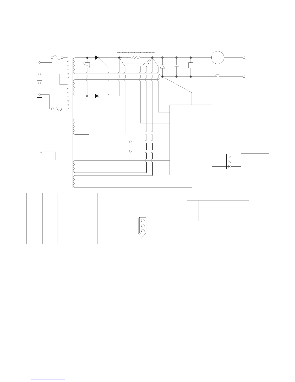
3. THEORY OF OPERATION
When the charger is connected to the desired AC
voltage source (115 or 230), the transformer creates
auxiliary voltages for the electronic control module.
The electronic control module controls and monitors
the charger so it will perform properly. The
transformer also supplies the power output used for
charging the batteries and provides electrical
isolation between the charger's output and the AC
source.
The charger's output current flows through a shunt
and is sensed by the electronic control module along
with the charger's output voltage. These values are
converted into drive pulses for the SCRs by the
control module. This pulsating charge current (a
pulse occurs each time an SCR is on) is then filtered
by a large capacitor and the batteries to provide a
smooth output.
The charger is an "IE" profile which is: (a) High rate
constant current, and (b) Constant voltage. When
the charger is first started, the SCRs will conduct for
a certain portion of the sinusoidal anode voltage to
provide the required charging current at the low level
of battery voltage. In this start region, a constant 30-
amp current is applied to the battery. The SCR
conduction will then increase as the battery voltage
increases in order to provide a higher output voltage
while maintaining a constant charging current.
When the battery voltage reaches the float voltage
(the voltage set with the switches), the SCRs will
start to decrease their output. This causes the
charger to automatically change from a constant
current charge region to a constant voltage charge
region. As the batteries become fully charged, the
output current decreases. A continuous constant
float voltage will be supplied to the batteries to
maintain their charge.
Another feature of the charger is temperature
compensation, which keeps the batteries from
getting under- or over-charged. TEMPERATURE
COMPENSATION ONLY OCCURS WHEN USING
A TEMPERATURE PROBE. The red LED on the
front of the charger will be off when using a
functional temperature probe. If the LED is on,
either a temperature probe is not being used, or the
temperature probe is working improperly.
Temperature compensation uses a temperature
reference of 77°F (25°C), a voltage reference of
2.23 volts (the voltage of a standard gel-cell battery
at 77°F), and a compensation value of 3.0 mV per
°F, or 5.4 mV per °C. The equivalent equation for
the compensated voltage is:
Vcomp = V – k (t - 77°F)
Where V is the voltage of the battery at 77°F, t is
the temperature in °F, and k = V (.003 / 2.23).
The control module has a temperature
compensation range between 32°F and 95°F (0°C
and 35°C) that does not allow charger voltage to
increase or decrease beyond the calculated values.
Example 1:
If a 26.8 volt battery is charging and the
temperature increases to 95°F, then the output
voltage decreases to 26.1 volts.
26.8 - .036 (95°F - 77°F) = 26.1
Example 2:
If a 29.00 volt battery is charging and the
temperature increases to 95°F, then the output
voltage decreases to 28.3 volts.
29.00 - .039 (95°F - 77°F) = 28.3
Example 3:
If 35.7 volt batteries are charging and the
temperature decreases to 32°F, the output voltage
increases to 37.9 volts.
35.7 – .048 (32°F - 77°F) = 37.9
4. RECEIVING AND INSTALLING THE
CHARGER
Proper installation of the charger is important in
order to achieve good charger performance and to
prevent damage to the charger and batteries. When
a charger is received, a check for possible in-transit
damage should be made. If any damage is found, it
should be reported as a claim to the carrier. To
permit free air flow for convention cooling, allow two
inches (2") minimum between the charger sides and
other equipment and four inches (4") minimum on
top of the charger.
WARNING: NEVER PLACE ANYTHING ON
TOP OF THE CHARGER WHILE OPERATING.
DAMAGE TO THE CHARGER OR BATTERIES
COULD OCCUR.
WARNING: THE CHARGER MUST BE SET
UP FOR THE PROPER USER SPECIFICATIONS
BEFORE STARTING THE INITIAL CHARGE.
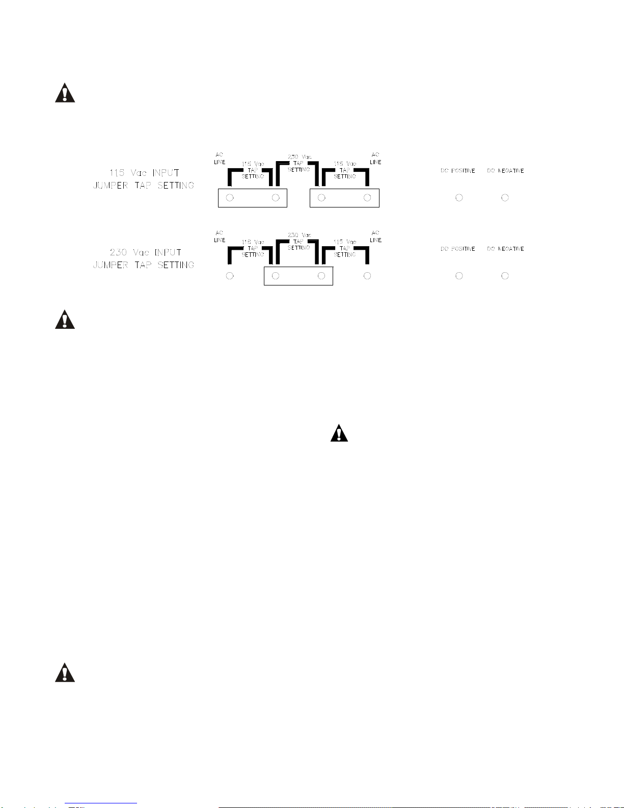
5. AC ELECTRICAL SUPPLY
The charger must be connected to a single-phase,
50-60 Hertz AC power source, which can be either
115 or 230 VAC. Use 8 or 10 AWG wire for the AC
power input. Quarter-inch (¼") ring terminals are
required for proper connection to the AC input and
ground binding posts (A.A.R.) located on the front of
the charger. Remove the small door cover on the
front of the charger by removing the two retaining
screws. On the panel behind the binding posts is a

www.nationalrailwaysupply.com
1-800-357-3572 3 01546G
diagram showing the proper jumper connections for
the different AC voltages.
WARNING: IMPROPER JUMPER
CONNECTION MAY CAUSE SEVERE DAMAGE
TO THE CHARGER AND THE BATTERY.
Configure the jumpers for your AC voltage source
(refer to the jumper diagram). Place the AC ring
terminals on the binding posts and tighten the post
nuts.
WARNING: FAILURE TO PROPERLY
CONNECT THE AC VOLTAGE CONDUCTORS
COULD CAUSE SERIOUS DAMAGE TO THE
CHARGER. IMPROPER GROUNDING CAN
RESULT IN THE RISK OF AN ELECTRIC SHOCK.
DO NOT OPERATE THE CHARGER WITHOUT
PROPER GROUNDING.
6. DC OUTPUT
The DC output wires 8 AWG or larger, are
connected on the two right-most binding posts as
labeled on the panel behind the binding posts
(positive on the left and negative on the right). The
DC cables should have quarter-inch (¼") ring
terminals for connecting them to the binding posts.
Check to make sure the polarity of the DC output
wires is the same as those connected to the battery.
The charger will not operate in a reversed polarity
condition. WHEN CONNECTING THE DC WIRES
TO THE CHARGER WITH THE AC POWER
DISCONNECTED, A SPARK MAY OCCUR. This is
caused by the output capacitors being charged by
the batteries. If the DC polarity is reversed, a circuit
breaker will protect the charger from internal
damage. Correct the reversed wires and push the
circuit breaker button back in. Replace the door
cover on the front of the charger after tightening all
of the binding post nuts.
WARNING: DO NOT TOUCH THE
CHARGER'S TERMINALS OR AN ELECTRICAL
SHOCK COULD OCCUR. A VOLTAGE IS
PRESENT ON THE DC TERMINALS EVEN AFTER
THE AC IS DISCONNECTED BECAUSE OF THE
ENERGY STORED IN THE CAPACITOR.
7. TEMPERATURE PROBE
The external temperature probe is an optional way
of extending battery life by using temperature
compensation. One end of the temperature probe
cable has a three-pin plug, which plugs into a
receptacle labeled TEMP PROBE on the front of the
charger. The other end of the cable has the
temperature sensor sealed either in a terminal or
small metal box.
WARNING: IT IS IMPORTANT TO MOUNT
THE TEMPERATURE PROBE ON THE
BATTERIES FOR PROPER TEMPERATURE
COMPENSATION. IF THIS CANNOT BE DONE,
LOCATE THE PROBE AS LOW AS POSSIBLE IN
THE BUNGALOW OR CABINET.
Terminal-Type Probe
The terminal-type probe should be attached to the
negative (-) battery post near the center of the
battery pack. If the threaded stud is long enough
above the battery jumper nut, attach the probe with
another nut. Torque this nut to proper specifi-
cations. If the stud is too short, the nut holding the
jumper wire will need to be removed. Open or
remove the load and charging circuits to the
batteries. Remove the nut holding the jumper and
add the probe, then torque the nut to the proper
specifications. Then close or connect the load and
charging circuits back to the batteries.
Box-Type Probe
The metal box has a high performance contact
adhesive tape for attaching it to the battery. To
attach, clean a spot for the probe on the middle

www.nationalrailwaysupply.com
1-800-357-3572 4 01546G
battery about three inches (3") down from the top of
the battery. Make sure the spot is free of all dirt and
oil or the probe will not adhere properly. For proper
adhesion, the battery surface must be cleaned with
isopropyl alcohol. Ideal application temperature
range is between 70 and 100°F. Initial application to
surfaces at temperatures below 50°F is not
recommended. Under cold conditions, the surface
should be warmed before application. Once
properly applied, low temperatures will not affect the
bond strength.
Remove the adhesive's protective strip and press
the probe firmly against the battery to ensure good
adhesion.
Securely fasten the temperature probe cable to
protect the probe from being torn from the
battery. Secure the probe's cable to a fixed object
to ensure the probe will not be pulled loose. Use a
cable tie mount on the battery or on the adjacent
battery, if necessary.
8. OPERATION
The battery charger is adjustable with the three
rotary switches on the front of the charger. The
switches (settable between 20.00 and 39.99)
determine the float voltage for the batteries. SET
THE FLOAT VOLTAGE TO THE BATTERY
MANUFACTURER'S SPECIFIED VOLTAGE FOR
77°F. The charger will then electronically charge the
batteries to the voltage specified on the switches.
To set the switches, use a small screw-driver and
turn the switch so that the arrow head on the slot is
pointing to the desired number. Set the switches in
the following manner. If the desired battery voltage
is 26.8 volts, set the top switch to 2, the middle
switch to 6, and the bottom switch to 8 (see the
figure below). This will provide you with the proper
charging voltage. BE SURE EACH SWITCH IS
SET ON A NUMBER AND NOT BETWEEN
NUMBERS. If a switch is set between numbers, the
output current will go to zero and the yellow charging
LED will flash.
The charger does not have a power switch. When
the AC power is applied to the charger, the DC
output will start and the yellow LED will be on. To
turn off the charger, disconnect the AC power
source.
9. MAINTENANCE
The battery charger requires minimal maintenance.
It should be kept clean and all connections are to be
periodically tightened. BE SURE THE CHASSIS IS
SECURELY GROUNDED. If any problem cannot
be resolved, consult the nearest NRS service agent
at 1-800-357-3572.
10. SERVICING
If the battery charger operates improperly, follow the
steps below.
a. Begin by checking the voltage switches to
verify their settings against the specifi-
cations of the batteries.
b. Next, remove the small cover on the front of
the charger and make sure all of the binding
post nuts are tight. Also check the jumper
tap configuration for the AC voltage used.
c. Check the fuses to make sure they have not
blown.
d. Check the circuit breaker to see if it has
opened and push it in to reset it if
necessary.
e. Check the polarity between the DC output
and the battery and make sure their
connections are tight.
f. If the steps above do not solve the problem,
contact your local NRS service agent at
1-800-357-3572.
11. CHARGER SPECIFICATIONS
AC INPUT VOLTAGE:
115 VAC (100-128) or 230 VAC (200-256)
AC INPUT CURRENT:
16.0 amps for 115 VAC (full power)
7.5 amps for 230 VAC (full power)
AC INPUT FREQUENCY:
48 – 65 Hertz (single phase)
AC LINE REGULATION:
For a constant output current at 2.00 volts/cell
+ 5.6% for 18 cells
+ 13.1% for 16 cells
AC FUSES:

www.nationalrailwaysupply.com
1-800-357-3572 5 01546G
MDA 12 or equivalent
POWER FACTOR:
Percentage at 30.0 amps DC current
91% for 18 cells
71% for 12 cells
DC OUTPUT:
Voltage range 20.00 – 39.99 + 0.2 volts
Current Maximum 30.0 + 5 amps
DC OUTPUT RIPPLE (at battery terminals):
1.4V p-p at 30.0 amps, 24.0 volts
0.28V p-p at 2.0 amps, 26.8 volts
TEMPERATURE COMPENSATION:
3+25mV per °F per cell
WEIGHT, NET:
58.0 lbs.
DIMENSIONS:
W = 18¼" H = 11¼" D = 9¾"
12. PARTS LIST
The following is a list of parts found in the NRS Model 24/30. When replacing a part, use only original factory
replacement parts of the correct size and rating.
PART NO. QTY DESCRIPTION
12895S 1 TRANSFORMER ASSEMBLY
17011S 2 SCR ASSEMBLY
18696S 1 SHUNT ASSEMBLY
14241S 2 AC INPUT JUMPERS
29102S 1 CONTROL MODULE (W/ ELECTRONIC BOARD #21185)
14123S 1 TEMPERATURE TRANSDUCER, 10' (BOX W/ ADHESIVE)
14126S 1 TEMPERATURE TRANSDUCER, 30' (BOX W/ ADHESIVE)
29741S 1 TEMPERATURE TRANSDUCER, 10' (W/ TERMINAL)
29742S 1 TEMPERATURE TRANSDUCER, 30' (W/ TERMINAL)
04401S 1 TRANSFORMER CAP
15032S 2 OUTPUT CAP
15037S 1 CIRCUIT BREAKER ASSEMBLY
22908S 1 COVER ASSEMBLY
14786S 1 DIODE ASSEMBLY
14484S 1 TERMINAL TAP STRIP
03837S 2 FUSEHOLDER, ASSEMBLY
15197S 1 VARISTOR ASSEMBLY W/ CAP, VR1
15029S 2 FUSE
14789S 1 TAP STRIP ASSEMBLY, W/ I/O STUDS
14759S 1 VARISTOR ASSEMBLY, VR2
14197S 4 BUSHINGS, 1" DIA.
31126B 1 VARISTOR ASSEMBLY, AC, 320V, LOT SIZE 10
22942S 1 AMMETER, 40 AMP, SNAP-IN
27319S 1 AMMETER, 50 AMP, CORNER MOUNT
22904S 1 BASE ASSY
15194S 1 HEATSINK ASSY, W/ SCR
23059S 1 CONTROL CABLE
The adhesive used on the temperature probes (#14123S and #14126S) is 3M Scotch #Y-9473 which is a
thermally conducting two-sided adhesive tape. If a replacement adhesive is needed, use this type of tape or an
equivalent adhesive.

www.nationalrailwaysupply.com
1-800-357-3572 6 01546G
13. WIRING DIAGRAM
AC FUSE
+C
C OUTPUT CAPACITOR
AC FUSE
3
2
1
VLT
BLU
GRY P1
PROBE
TEMPERATURE
REMOTE
D DIODE ASSEMBLY
SHOWN
SETTING
115V
BLK
BLK
BLK
AS VIEWED FROM OUTSIDE CHARGER
VR2 VARISTOR
VR1 VARISTOR WITH CAP
D
VR1 VR2
MODULE
CONTROL
BREAKER
CIRCUIT
DETAIL
CONNECTOR
P1
1
2
3
WHT
WHT
SHUNT
GND
8
BLK
12
11
10
7
6
5
9
4
3
2
1
-BATTERY
+BATTERY
BLK
ORG
AC
AC
YEL
RED
BRN
BRN
SCR
SCR
BLK BLK
ELECTRONIC
A
J1-1
J1-7
J1-9
J1-8
J1-10
J1-11
J1-6
J1-5
J1-3
J1-12
J1-4
BLK
ORANGE SHUNT-
YELLOW SHUNT+
BLACK -BATTERY
BROWN SCR
BROWN SCR
WHITE AC XFRMR #5
WHITE AC XFRMR #8
RED +BATTERY
J1-8
J1-9
J1-1
J1-10
J1-11
J1-6
J1-5
J1-7
TMP PROBE (-)J1-3
J1-12 TEMP PROBE SENSE
J1-4 TEMP PROBE (+)
GRAY
BLUE
VIOLET
J1-2 NOT USED
JUMPER
14
13
C1
G
G
AC
LINE
LINE
AC
This manual suits for next models
1
Table of contents
Other National Railway Supply Batteries Charger manuals