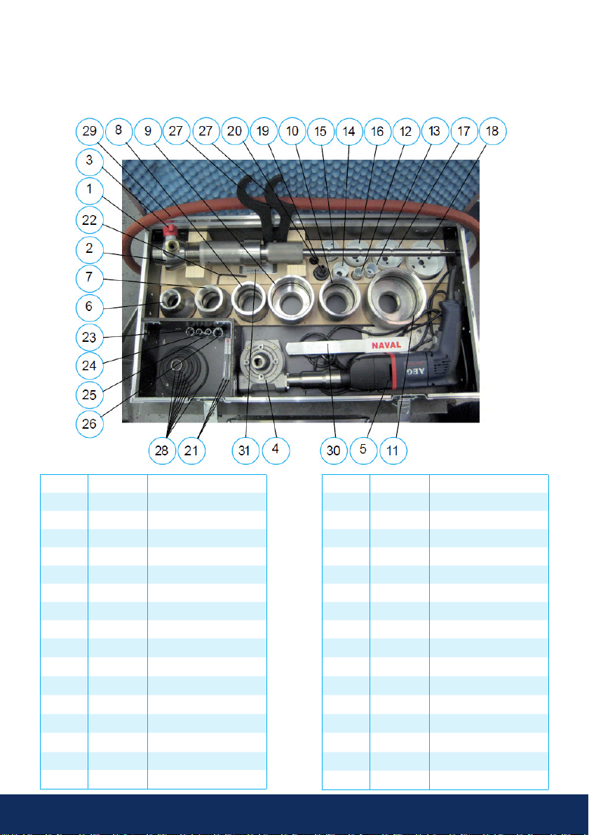
Naval DN 25 User manual

Instructions for Naval hot tapping
equipment and valves

2 3
www.vexve.com
Contents
1. List of parts
1.1. 287195 DN 25–100 4
1.2. Exploded view 6
2. Preparations 7
2.1. Preparing the pipe and valve 7
2.2. Preparing the hot tapping drill 8
3. Hot tapping 9
3.1. Checklist for power drill 9
3.2. Drilling 10
3.3. Technical criteria for power drill 10
4. Installation dimensions and RPM settings 11
4.1. DN 25 11
4.2. DN 32 12
4.3. DN 40 13
4.4 DN 50 14
4.5. DN 65 15
4.6. DN 80 16
4.7. DN 100 17
4.8. DN 125/150 18
4.9. Full bore DN 150 19
4.10. DN 200 20
5. Hot tapping through DN 150 full bore valve 21

2 3
www.vexve.com www.vexve.com
NOTE:
This manual must be read and its instructions must be followed when installing, operating
and/or performing maintenance on the valve as well as its manual gear or actuator.
These instructions are of general nature and do not cover all possible operating scenarios. For more
specific guidance on the installation, operation and maintenance of the valve or its suitability for an
intended use, please contact the manufacturer.
Vexve Oy reserves the right to make alterations to these instructions.
Vexve Oy is not responsible for damages caused by incorrect transportation, handling, installation,
operation or maintenance. Furthermore, Vexve Oy is not responsible for damage caused by foreign
objects or impurities.
Warranty
Warranty according to Vexve Oy’s “General terms and conditions of sale”.
The warranty covers manufacturing and material faults. The warranty does not apply to damages
caused by inappropriate installation, operation, maintenance, or storage ie. these instructions must be
followed for the warranty to apply. Vexve Oy requires that any faulty products under warranty are to be
returned to the factory for inspection. Only after the product has been found faulty, Vexve Oy can grant
compensation.
Please refer to Vexve Oy’s “General terms and conditions of sale” for detailed warranty clauses. The
document is available from the manufacturer
Warnings and symbols
Ignoring the warnings and symbols may lead to serious injury or equipment damage. Persons authorized
to use the equipment must be familiar with the warnings and instructions.
Appropriate transportation, storage and installation as well as careful commissioning are essential to
ensure faultless and stable operation.
The following symbols are used in this manual to draw attention to actions essential to ensure the proper
use and safety of the device.
Meaning of the symbol: NOTE
The NOTE symbol is used for actions and functions that are essential for the proper use of
the device. Ignoring this symbol may have harmful consequences.
Meaning of the symbol: WARNING
The WARNING symbol is used for actions and functions that, if carried out incorrectly, may
lead to injury or equipment damage.
© 2020 Vexve Oy - All product names, trademarks and registered trademarks are property of Vexve Oy.

4 5
www.vexve.com
1. List of Parts
1.1. 287195 DN 25–100
Part nro Code Description
1 400001 Case for equipment
2 400062 Frame assembly
3 286152 Draining valve
4 400061 Angle attachment
5 400009 Power drill
6 400027 Adapter, DN 20-25
7 400028 Adapter, DN 32-40
8 400029 Adapter, DN 50
9 400030 Adapter, DN 65
10 400031 Adapter, DN 80
11 400032 Adapter, DN 100
12 400042 Hole saw, DN 25
13 400043 Hole saw, DN 32
14 400044 Hole saw, DN 40
15 400045 Hole saw, DN 50
16 400046 Hole saw, DN 65
Part nro Code Description
17 400047 Hole saw, DN 80
18 400048 Hole saw, DN 100
19 40003930 Drill chuck, DN 25-32
20 40004030 Drill chuck, DN 40-150
21 400049 Pilot drill bit, 6.5 mm
22 400055 Hex key, 4 mm
23 400075 Socket, 6k-9
24 400076 Socket, 6k-10
25 400077 Socket, 6k-15
26 400078 Socket, 6k-19
27 400050 Hook wrench, 80-90 mm
28 400056* Set of seals
29 Draining valve hose
30 288752 Handle, ½”, DN 25-150
31 298803 Sticker

4 5
www.vexve.com www.vexve.com
Code Description
400033 O-ring, D33 x 3 FPM for DN 20–25 adapter
400034 O-ring, D47 x 3 FPM for DN 32–40 adapter
400035 O-ring, D58 x 5 FPM for DN 50 adapter
400036 O-ring, D75 x 5 FPM for DN 65 adapter
400037 O-ring, D88 x 5 FPM for DN 80 adapter
400038 O-ring, D113.67 x 5.33 FPM for DN 100 adapter
400026 O-ring, D60 x 5 FPM
400022 Shaft seal, D20/30 x 7
*400056 contains:

6 7
www.vexve.com
2.1. Exploded view

6 7
www.vexve.com www.vexve.com
2. Preparations
2.1 Preparing the pipe and valve
Locate the exact point for the joint on the main pipe line and prepare the main pipe for welding of the
valve. Check the place of the joint on the main pipe (if the main pipe is a weld seam tube, avoid welding
the hot tapping valve on the weld seam).
Prepare the weld end of the hot tapping valve to match the radius (“R”) of the main pipe and taper the
edges as required for the best welding result (see figure 1).
The weld seam has to comply with the local requirements for size and strength. A support collar is to be
used when necessary.
NOTE: The threaded end of the valve may be prepared for welding or shortened only after
drilling through the main pipe.
Figure 1.

8 9
www.vexve.com
2.2. Preparing the hot
tapping drill
Select the hole saw that corresponds to the
valve’s DN size. Also select a drill chuck and
adapter of corresponding size from the case.
First install the adapter to the tool and after that
install the drill chuck assembly (drill chuck + pilot
drill bit + hole saw) on the shaft of the tool.
Check that the edge of Frame I is aligned with
the groove on Frame II (see figure 4, the groove
is on the threaded area of Frame II). This setup
corresponds to the maximum feeding distance.
This position must not be exceeded under any
circumstances when the tool is pressurized.
Make sure that the valve is fully OPEN. Attach
the complete tool assembly to the threads on the
valve and test that the hole saw can freely slide
through the ball in the valve.
After welding, the tightness of the seam can be tested e.g. by pressure testing the joint with compressed
air through the hot tapping tool’s draining valve.
Figure 2. Figure 3.
Figure 4.
The valve may be welded to the main pipe at any angle between 0° and 360° (see figure 2), but it must be
at a 90° angle to the longitudinal axis of the main pipe (see figure 3).

8 9
www.vexve.com www.vexve.com
Attach the draining valve with hose to Frame II and close the draining valve.
Before drilling through the main pipe, test that the valve can be closed: release the shaft’s locking
mechanism by pulling the spring loaded part # 400012 (see page 6) and slide out the shaft until it
mechanically stops at the outermost position. Close and open the hot tapping valve to verify it is working
properly.
Select a locking position that corresponds to the size of the hot tapping valve and lock the shaft to the
selected position (three alternatives —> see page 6).
3. Hot tapping
3.1. Checklist for power drill
· the rotation direction must be clockwise
· the percussion function must not be on under any circumstances
· select rotation speed: area 1 or 2 (see figure 5)
· set RPM, scale A – F (see figure 6).
Figure 5. Figure 6.

10 11
www.vexve.com
3.2. Drilling
When starting the drilling, i.e. when drilling the pilot hole, use high RPM (460 RPM), area 2 and scale F.
Feed the drill through steadily and smoothly. During drilling, it is recommended to keep the draining valve
open to remove the cuttings.
Stop after only drilling through with the pilot drill bit. Adjust the speed of rotation area (1 or 2) and scale
(A-F) for the actual hole cutting and close the draining valve.
Feed the hole saw through steadily and smoothly. During cutting, you may keep the draining valve open;
close it after finishing.
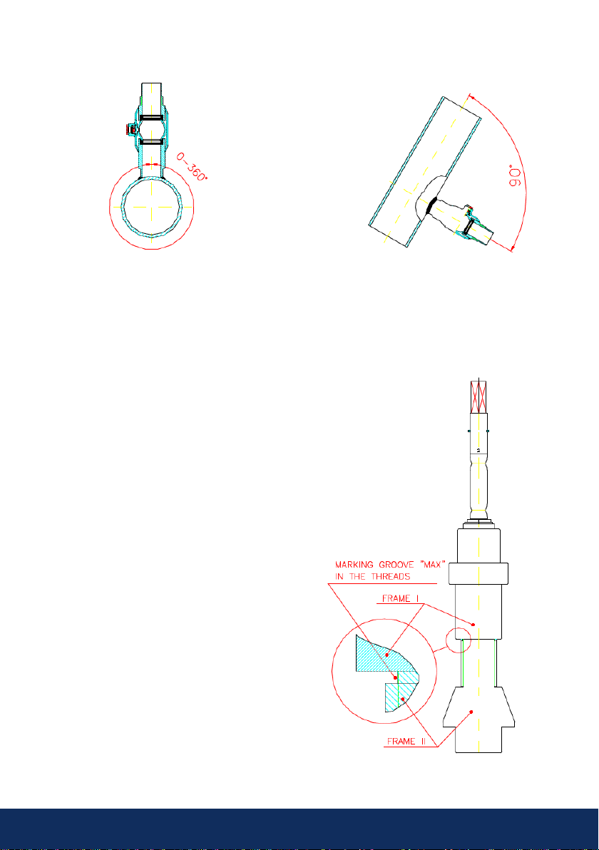
Release the shaft locking mechanism and slide the shaft to its outermost position (due to pressure in
the valve, the shaft slides out automatically), then close the hot tapping valve. Open the draining valve to
release the pressure from the hot tapping valve.
WARNING: Before releasing the shaft’s locking mechanism, move your head away from
shaft’s end to avoid impact. The shaft will slide out rapidly under water pressure.
NOTE: Before removing the drilling tool from the hot tapping valve, make sure that the valve
is fully closed; check the markings at the stem. The tightness of the hot tapping valve must
be verified by using the draining valve: no water must flow through the draining valve after the
hot tapping valve is closed.
After the drilling is finished, it is important to clean the hot tapping tool from any metal chips and other
impurities that have come in the drilling process.
Disassemble the hot tapping drill: first, remove the draining valve and after that remove the tool (incl.
adapter) from the hot tapping valve. Then disassemble the drill in the reverse order as you had assembled
it.
Closing the stem by welding: If required, the stem can be permanently closed by welding. Remove the
PTFE sealing underneath the cap before welding.
3.3 Technical criteria for power drill
We recommend the following power drills:
Milwaukee PD2E 24RS
AEG SB2E 1200 RST
If you use another drill, make sure that it fulfills the following criteria:
· input power min. 1000 W
· speed of rotation areas: Area 1: 0 – 1000 RPM Area 2: 0 – 3000 RPM
· required speed adjustments are available for dierently-sized hole saws
· the drill’s neck diameter must be 43 mm
NOTE: If you select another brand or model, please check with the manufacturer that it fulfills
above mentioned criteria.

10 11
www.vexve.com www.vexve.com
4. Installation dimensions and RPM settings
4.1. DN 25
Locking groove No. 1 Hole saw Ø 24 mm
Speed: 370 RPM
Area 2
Scale D
With main pipeline sizes DN 32, the feeding of the saw must be
stopped at least 10 mm before the maximum feeding distance.
The “A” dimensions are valid for Lenox and Sandvik hole saws.
Main pipeline: nominal size A B C
DN 32 99 +0
-5 20 105
DN 40 100 +0
-10 20 105
DN 50 101 +0
-10 20 105
DN 65 102 +0
-10 20 105
DN 80 102 +0
-10 20 105
DN 100 103 +0
-10 20 105
DN 125 103 +0
-10 20 105
DN 150 103 +0
-10 20 105
DN ≥ 200
105
+0
-10 20 105

12 13
www.vexve.com
4.1. DN 32
Locking groove No. 1 Hole saw Ø 30 mm
Main pipeline: nominal size A B C
DN 40 85 +2
-0 20 93
DN 50 87 +0
-10 20 93
DN 65 89 +0
-10 20 93
DN 80 90 +0
-10 20 93
DN 100 91 +0
-10 20 93
DN 125 91 +0
-10 20 93
DN 150 92 +0
-10 20 93
DN 200 92 +0
-10 20 93
DN 300 92 +0
-10 20 93
DN 400 92 +0
-10 20 93
DN ≥500 93 +0
-10 20 93
Speed: 285 RPM
Area 2
Scale C1
When drilling through a DN 40 pipe, feeding must be stopped
10 mm before the maximum feeding distance, and when drilling
through a DN 50 pipe, it must be stopped 15 mm before the
maximum feeding distance. With other pipe sizes, the maximum
feeding distance can be used.
The “A” dimensions are valid for Lenox and Sandvik hole saws.

12 13
www.vexve.com www.vexve.com
4.1. DN 40
Locking groove No. 2 Hole saw Ø 38 mm
Main pipeline: nominal size A B C
DN 50 90 +0
-10 20 111
DN 65 93 +0
-10 20 111
DN 80 94 +0
-10 20 111
DN 100 95 +0
-10 20 111
DN 125 96 +0
-10 20 111
DN 150 96 +0
-10 20 111
DN 200 97 +0
-10 20 111
DN ≥300 98 +0
-10 20 111
Speed: 230 RPM
Area 2
Scale B1
For pipe sizes DN ≥100 with wall thickness ≥ 10 mm, it is
recommended to deduct 10 mm from the above ”A” dimensions to
guarantee that the hole saw goes fully through the wall of the main
pipe.
The above ”A” dimensions are valid for Lenox holesaws. When
using a Sandvik hole saw, an additional 10 mm must be deducted
from these dimensions (A 38 mm diameter Sandvik hole saw is
10 mm lower than an equivalent Lenox one).

14 15
www.vexve.com
4.1. DN 50
Locking groove No. 2 Hole saw Ø 48 mm
Main pipeline: nominal size A B C
DN 65 120 +0
-0 20 131
DN 80 121 +0
-10 20 131
DN 100 124 +0
-10 20 131
DN 125 126 +0
-10 20 131
DN 150 127 +0
-10 20 131
DN 200 128 +0
-10 20 131
DN 300 129 +0
-10 20 131
DN 400 129 +0
-10 20 131
DN ≥500 131 +0
-10 20 131
Speed: 180 RPM
Area 1
Scale E
When drilling a DN 65 pipe, feeding must be stopped 10 mm
before the maximum feeding distance.
The ”A” dimensions are valid for Lenox and Sandvik hole saws.

14 15
www.vexve.com www.vexve.com
4.1. DN 65
Locking groove No. 2 Hole saw Ø 64 mm
Main pipeline: nominal size A B C
DN 80 111 +2
020 140
DN 100 116 +2
020 140
DN 125 118 +2
020 140
DN 150 120 +2
020 140
DN 200 122 0
-5 20 140
DN 300 124 0
-5 20 140
DN 400 125 0
-5 20 140
DN 500 126 0
-5 20 140
DN 600 126 0
-5 20 140
DN ≥800 126 0
-5 20 140
Speed: 135 RPM
Area 1
Scale C
The ”A” dimensions are valid for Lenox and Sandvik hole saws.

16 17
www.vexve.com
4.6. DN 80
Locking groove No. 3 Hole saw Ø 76 mm
Main pipeline: nominal size A B C
DN 100 173 0
-5 20 204
DN 125 177 0
-5 20 204
DN 150 180 0
-5 20 204
DN 200 183 0
-5 20 204
DN 250 185 0
-5 20 204
DN 300 186 0
-5 20 204
DN 400 186 0
-5 20 204
DN 500 187 0
-5 20 204
DN 600 188 0
-5 20 154
DN ≥800 188 0
-5 20 154
Speed: 115 RPM
Area 1
Scale B
The ”A” dimensions are valid for Lenox and Sandvik hole saws.
It is necessary to weld 50 mm prolongation pipe to the valve weld
end so that measurement C=204 mm can be achieved.

16 17
www.vexve.com www.vexve.com
4.7. DN 100
Locking groove No. 3 Hole saw Ø 95 mm
Main pipeline: nominal size A B C
DN 125 131 +2
020 157
DN 150 136 +2
020 157
DN 200 141 +0
-2 20 157
DN 250 144 +0
-2 20 157
DN 300 147 +0
-5 20 157
DN 400 148 +0
-5 20 157
DN 500 150 +0
-5 20 157
DN 600 150 +0
-5 20 157
DN ≥800 152 +0
-5 20 157
Speed: 90 r/min
Area 1
Scale A
The ”A” dimensions are valid for Lenox and Sandvik hole saws.

18 19
www.vexve.com
4.8. DN 125/150
Locking groove No. 3 Hole saw Ø 121 mm
Main pipeline: nominal size A B C
DN 200 153 +0
-10 20 175
DN 250 158 +0
-10 20 175
DN 300 161 +0
-10 20 175
DN 400 165 +0
-10 20 175
DN 500 165 +0
-10 20 175
DN 600 168 +0
-10 20 175
DN ≥800 170 +0
-10 20 175
Speed: 75-90 RPM
Area 1
Scale A
The ”A” dimensios are valid for Lenox and Sandvik hole saws.

18 19
www.vexve.com www.vexve.com
4.9. Full bore DN 150
Locking groove No. 2 Hole saw Ø 146 mm
Main pipeline: nominal size A B C
DN 200 230 +0
-10 20 265
DN 250 240 +0
-10 20 265
DN 300 245 +0
-10 20 265
DN 400 250 +0
-10 20 265
DN ≥500 255 +0
-10 20 265
Speed: 75-90 RPM
Area 1
Scale A
The ”A” dimensions are valid for Lenox and Sandvik hole saws.

20 21
www.vexve.com
4.10. DN 200
Locking groove No. 2 Hole saw Ø 146 mm
Main pipeline: nominal size A B C
DN 250 240 +0
-10 20 265
DN 300 245 +0
-10 20 265
DN 400 250 +0
-10 20 265
DN ≥500 255 +0
-10 20 265
Speed: 75-90 RPM
Area 1
Scale A
The ”A” dimensions are valid for Lenox and Sandvik hole saws.
This manual suits for next models
9
Table of contents