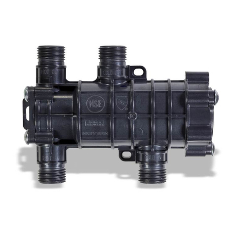
Navien NaviCirc Series User manual

Installation and Operation
Manual
Certified to
NSF / ANSI 372
Note This device is designed
and optimized for use only
on Navien NPE-A water
heaters.
WARNING
All Installations should be done only by a qualied expert and
in accordance with the appropriate Navien manual. Improper
installation of this device may result in serious injury or property
damage.
When Installing the NaviCirc:
●Read these instructions carefully. Failure to comply could
damage the NaviCirc or cause a hazardous condition.
●Check the ratings provided in the instructions and on the
product to make sure the product is suitable for the application.
●Installers must be trained, experienced, and licensed service
technicians.
●Follow local codes for installation and application requirements.
Downloaded from https://gadgetsgo.com/Navien-NaviCirc-30022965A-retrofit-recirc-valve.html

2
1. About the NaviCirc 3
1.1 Included Items 3
1.2 Specications 4
1.3 Compatible Products & Pump Requirements 5
1.4 Conguration 6
1.5 Supply Connections 7
2. Application System 8
2.1 NPE-A System 8
2.1.1 Application Guidelines 8
2.1.2 NPE-A System Diagram 12
2.2 Installing the NaviCirc 16
2.2.1 Installing the NaviCirc 17
2.2.2 Leak Check & Air Purge 18
2.3 Securing the NaviCirc to the Wall 19
3. Troubleshooting 20
Contents
Downloaded from https://gadgetsgo.com/Navien-NaviCirc-30022965A-retrofit-recirc-valve.html

3
After the installation is complete, verify proper operation of the
NaviCirc by following the instructions provided in this manual.
1. About the NaviCirc
NaviCirc is a circulation device for standard domestic hot water lines
without a recirculation system. It allows domestic hot water lines
and domestic cold water lines to connect to the NaviCirc and pre-
heat hot water lines by circulating hot and cold water through the
NaviCirc. This prevents hot water loss and heating time loss.
To prevent too much hot water from owing into the cold water line,
the NaviCirc includes a feature that automatically blocks circulation
when reaching a temperature of approximately 95°F (35°C).
1.1 Included Items
NaviCirc
(Recirculation Valve)
Installation and Operation
Manual
Anchors and Screws Flexible Hoses (with kit only)
Downloaded from https://gadgetsgo.com/Navien-NaviCirc-30022965A-retrofit-recirc-valve.html

4
1.2 Specications
Refer to the following table for product specications.
Items Specications
Product name NaviCirc
Part number PFFW-SXX-001
Water ow rate range 0.53 - 1.06 GPM (2.0 - 4.0 LPM)
Crossover shuto temperature 95℉(35℃)
Water temperature range 41℉to 180℉ (5℃to 82℃)
Ambient temperature range 32 - 122℉ (0 - 50℃)
(Indoor use only)
Storage temperature range 23 - 122℉ (-10 - 50℃)
Max water pressure 150 psi
Installation operation Horizontal
Dimensions (in) 5.62 x 3.93 x 2.19
Weight (lb) 1.10 lb (0.5 kg)
Downloaded from https://gadgetsgo.com/Navien-NaviCirc-30022965A-retrofit-recirc-valve.html

5
1.3 Compatible Products & Pump
Requirements
The NaviCirc is most compatible with Navien NPE-A Series water
heaters.
NPE-A models may utilize the built-in pump along with the
appropriate piping to create a hot water recirculation loop. If
the NaviCirc is used on a non-Navien appliance, consult the
manufacturer for compatibility and size the pump with the
following head requirements:
Pump MAX head approx. 15 ft (4.6 m) – 23 ft (7 m)
Note Navien does not guarantee the performance of the
NaviCirc when used on a non-Navien appliance.
CAUTION
If the selected external pump does not meet the recommended
specications provided in this manual, the NaviCirc may not
operate properly.
Downloaded from https://gadgetsgo.com/Navien-NaviCirc-30022965A-retrofit-recirc-valve.html

6
1.4 Conguration
Refer to the following diagram for the NaviCirc layout.
Faucet
hot water
connection
Hot water
inlet
connection
Cold water
inlet
connection
Faucet
cold water
connection
Downloaded from https://gadgetsgo.com/Navien-NaviCirc-30022965A-retrofit-recirc-valve.html

7
1.5 Supply Connections
Refer to the following table for the NaviCirc supply connection
specications.
A
C D
B
A
C
D
B
Front view Side view
List Connection
AHot water outlet ½” NPS
BCold water outlet ½” NPS
CHot water inlet ½” NPS
DCold water inlet ½” NPS
Dimension (in) 5.62 x 3.93 x 2.19
Supply Connections
Downloaded from https://gadgetsgo.com/Navien-NaviCirc-30022965A-retrofit-recirc-valve.html

8
2. Application System
2.1 NPE-A System
2.1.1 Application Guidelines
See the installation guidelines below for additional instructions.
1. Locate the 10-switch set of dipswitches on the front panel and
verify that DIP SW2 is ON for EXTERNAL recirculation.
1 2 3 1 24 5 6 7 8 9 10
ON ON
1-OFF
2-ON
2. On the front panel, press the Power button to turn o the
water heater.
3. Enter the R&D information menu by pressing the Up [+] button
three times, the Down [-] button three times, and then the Up
[+] button four more times.
Note Maximum recirculation pipe lengths:
●100 feet (30 m) equivalent length of ½”copper pipe
●400 feet (120 m) equivalent length of ¾”copper pipe
Downloaded from https://gadgetsgo.com/Navien-NaviCirc-30022965A-retrofit-recirc-valve.html

9
4. In the R&D information menu, use the Up [+] or Down [-]
button to move to 2.PAR (Parameter information mode), and
then press the Information button.
No. Mode Display
1 Technical information
2 Parameter information
5. Use the Up [+] and Down [-] buttons to enter Parameter #17
(P.17 – Enable Thermal Bypass Valve).
Item Name Description Display
P17 Enabler thermal
bypass valve
Set thermal bypass
valve operation
(Required Adjustments to the Available Parameters)
Downloaded from https://gadgetsgo.com/Navien-NaviCirc-30022965A-retrofit-recirc-valve.html

10
6. Use the Up [+] or Down [-] button to move to adjust the
parameter option to 2. ON.
Range Description Display
1.OFF Thermal bypass valve is disabled.
2. ON Thermal bypass valve is enabled.
Null Setting for S-type models, Panel DIP3
ON, Cascade ON, or AHU is enabled.
Note ●Additional parameters are available to adjust unit
operation for various plumbing systems. Refer to
the NPE Installation & Operation Manual for more
information on these parameters.
Items Description
Pump Cycle
Interval Time
(P.12)
Sets the maximum time that the
internal circulator will operate once a
recirculation cycle has been initiated.
●Setting range: 1 to 120
(in 1-minute increments)
●Default: 20 min
Note
When the optional HotButton
accessory is installed, the maximum
setting value is limited to 5 minutes.
Downloaded from https://gadgetsgo.com/Navien-NaviCirc-30022965A-retrofit-recirc-valve.html

11
Items Description
Return Line
Sampling Time
(P.14)
Sets the length of time that the
circulator will operate periodically in
order to check the temperature of the
recirculation return line and see if it
needs to be re-heated.
●Setting range: 1 to 120
(in 1-minute increments)
●Default: 30 min
●Set the 2-way valve inside the water heater to“EXT.”
Downloaded from https://gadgetsgo.com/Navien-NaviCirc-30022965A-retrofit-recirc-valve.html

12
2.1.2 NPE-A System Diagram
Follow the instructions to install the NaviCirc to the wall.
City water supply
1 2 3 4
ON
SW1
CE1
RA1
U1
CE1
C1
C2
C7
R6
SW1
Q1
12V SIGNAL
SIGNAL 1
GND
5V
J1R5
J2
C4
ZD1
R7
D1
CON3CON2
CON1
SIGNAL
SIGNAL 3
GND
SIGNAL2
Wired
push button
Wired
push button
Wired
push button
HotButton kit*
DHW supply
Return water
Navien NPE A
Water heater
Check Valve
(required)
S
Solenoid
Valve**
Expansion tank***
Ball
Valve
Ball
Valve
Ball
Valve
Flexible
hoses
Flexible
hoses
Note
A branch from the cold water line must
be connected to the RECIRCULATION
RETURN water connection located on
the water heater. Additionally, the end
user might experience lukewarm water
when rst opening the cold water tap.
Maximum recirculation pipe lengths:
●100 feet (30 m) equivalent length
of ½” copper pipe
●400 feet (120 m) equivalent length
of ¾” copper pipe
* The HotButton kit is sold separately.
** Solenoid valve not required under
most conditions. Temperature
uctuations may occur during high
system ow rates.
*** Expansion tank only required if a
check valve is installed on the cold
water supply line or if required by
local codes.
Install the recirculation valve to the faucet furthest from the water
heater.
If installed in close proximity to the water heater, faucets further
away from the water heater will take longer to receive hot water.
Downloaded from https://gadgetsgo.com/Navien-NaviCirc-30022965A-retrofit-recirc-valve.html

13
2.1.2 NPE-A System Diagram
Follow the instructions to install the NaviCirc to the wall.
City water supply
1 2 3 4
ON
SW1
CE1
RA1
U1
CE1
C1
C2
C7
R6
SW1
Q1
12V SIGNAL
SIGNAL 1
GND
5V
J1R5
J2
C4
ZD1
R7
D1
CON3CON2
CON1
SIGNAL
SIGNAL 3
GND
SIGNAL2
Wired
push button
Wired
push button
Wired
push button
HotButton kit*
DHW supply
Return water
Navien NPE A
Water heater
Check Valve
(required)
S
Solenoid
Valve**
Expansion tank***
Ball
Valve
Ball
Valve
Ball
Valve
Flexible
hoses
Flexible
hoses
City water supply
1 2 3 4
ON
SW1
CE1
RA1
U1
CE1
C1
C2
C7
R6
SW1
Q1
12V SIGNAL
SIGNAL 1
GND
5V
J1R5
J2
C4
ZD1
R7
D1
CON3CON2
CON1
SIGNAL
SIGNAL 3
GND
SIGNAL2
Wired
push button
Wired
push button
Wired
push button
HotButton kit*
DHW supply
Return water
Navien NPE A
Water heater
Check Valve
(required)
S
Solenoid
Valve**
Expansion tank***
Ball
Valve
Ball
Valve
Ball
Valve
Flexible
hoses
Flexible
hoses
Note
A branch from the cold water line must
be connected to the RECIRCULATION
RETURN water connection located on
the water heater. Additionally, the end
user might experience lukewarm water
when rst opening the cold water tap.
Maximum recirculation pipe lengths:
●100 feet (30 m) equivalent length
of ½” copper pipe
●400 feet (120 m) equivalent length
of ¾” copper pipe
* The HotButton kit is sold separately.
** Solenoid valve not required under
most conditions. Temperature
uctuations may occur during high
system ow rates.
*** Expansion tank only required if a
check valve is installed on the cold
water supply line or if required by
local codes.
Install the recirculation valve to the faucet furthest from the water
heater.
If installed in close proximity to the water heater, faucets further
away from the water heater will take longer to receive hot water.
Downloaded from https://gadgetsgo.com/Navien-NaviCirc-30022965A-retrofit-recirc-valve.html

14
Installing the Solenoid Valve (optional)
A Navien external pump wire (#GXXX001319) is needed to
complete the solenoid valve installation. See the installation
guidelines below.
1. Make sure that the system power is o before proceeding with
the installation of the wiring.
2. Remove the front cover from the unit and remove the PCB by
removing the 2 attaching screws from the housing.
3. Use a 120 VAC (max 1.5 A) normally closed solenoid valve for
this application (a slow closing solenoid is recommended to
prevent water hammer).
4. Connect the external pump wire to the proper wires from the
solenoid valve.
5. Remove the 2 screws holding the PCB box in place and
remove the PCB box from the system.
Remove Screws here.
Downloaded from https://gadgetsgo.com/Navien-NaviCirc-30022965A-retrofit-recirc-valve.html

15
6. Locate the TB1 connection on the PCB and attach the external
pump wire and solenoid valve assembly to this connector.
TB1
7. Locate the 10-switch set of dipswitches on the front panel and
verify that DIP SW2 is ON for EXTERNAL recirculation.
1 2 3 1 24 5 6 7 8 9 10
ON ON
1-OFF
2-ON
3-OFF
Downloaded from https://gadgetsgo.com/Navien-NaviCirc-30022965A-retrofit-recirc-valve.html

16
2.2 Installing the NaviCirc
Follow the instructions to install the NaviCirc to desired faucet
location.
Use existing hoses
(3/8” x 3/8“ or 1/2” x 1/2“)
Navien exible hoses
(supplied with kit only)
(1/2” x 3/8”) 3/8” to 1/2” adaptor
3/8” to 1/2” adapters
Hot and cold water
shut o valve (3/8”)
Downloaded from https://gadgetsgo.com/Navien-NaviCirc-30022965A-retrofit-recirc-valve.html

17
2.2.1 Installing the NaviCirc
1. Make sure that the install location is near the faucet furthest
from the water heater.
2. Close the hot and cold water inlet shuto valves.
3. Open both the hot and cold water faucets.
WARNING
Ensure that the hot and cold water faucets are open. Operating
the device without opening them will build water pressure and
may result in injury or death.
4. Disconnect the 3/8” (or 1/2”) hose that was originally connected
to faucet.
5. Secure the NaviCirc below the faucet in the desired location.
6. Connect the 3/8” to 1/2” adaptor to the NaviCirc HOT OUT and
COLD OUT (or the hot and cold shuto valves depending on
the shuto valve hose size) connections.
7. Connect the end of the existing 3/8” (or ½”) hot and cold water
hoses connected to the faucet to the HOT OUT and COLD
OUT connections.
Note Do not use Teon tape or adhesives on the
NaviCirc 1/2”male orices. Make sure to use hoses
with rubber gaskets.
8. Connect Navien supplied 1/2” to 3/8” ex line or other exible
hose to 3/8” hot and cold shuto valves with or without the
adaptor depending on the existing shuto valve hose size.
9. Connect the remaining 1/2”hot and cold water ex lines to the
NaviCirc HOT IN and COLD IN connections.
Downloaded from https://gadgetsgo.com/Navien-NaviCirc-30022965A-retrofit-recirc-valve.html

18
2.2.2 Leak Check & Air Purge
1. Close hot water and cold water faucets.
2. Open hot water and cold water shuto valves.
3. Open hot water and cold water faucets.
4. Check if there are leaks after connecting the hoses to the
NaviCirc.
Note In case of leaks, close the shuto valves and repair
any leaks.
5. Purge the air from the system by opening the hot water and
cold water faucet.
Note Perform an air purge so that all residual air can
properly leave the system pipes. If the air purge
is not performed long enough, the recirculation
valve may not operate properly. Also, residual air
can damage the recirculation pump.
Downloaded from https://gadgetsgo.com/Navien-NaviCirc-30022965A-retrofit-recirc-valve.html

19
2.3 Securing the NaviCirc to the Wall
Follow the instructions to install the NaviCirc to desired faucet
location.
Secure the NaviCirc with the three anchor bolts included with the
installation kit.
Note Do not forcefully secure the NaviCirc to the wall with
anchor bolts, as this can damage the system. Make
sure to place it horizontally in a xed position.
Downloaded from https://gadgetsgo.com/Navien-NaviCirc-30022965A-retrofit-recirc-valve.html

20
3. Troubleshooting
If you experience a problem with the NaviCirc, refer to the
following table for possible remedies.
Problem Possible cause(s) What to do
The water from the hot
water tap is not hot enough.
●Full temperature water has not
reached the xture.
●The hot water temperature of the
water heater is set too low.
●The pump is not operating properly.
●The pump is working, but hot water
does not reach the NaviCirc.
●NaviCirc is not installed properly.
●Keep the xture open to allow the hot water line to purge.
●Set the water heater temperature to a higher temperature.
●Check whether the pump is stuck.
●If NaviCirc is used on a non-Navien appliance, check that the pump is
properly sized and installed per the manufacturer's instructions.
●Clean out the water heater lter and the NaviCirc inlet.
●Contact Navien Technical Support.
The water from the hot
water tap is not hot enough
even when the water heater
is set at a high temperature.
●NaviCirc malfunction. ●Contact Navien Technical Support.
The water from the hot
water tap is too hot.
●The water heater temperature is set
too high.
●Adjust the water heater temperature.
Hot water comes out while
cold water is being used.
●NaviCirc is operating properly.
●NaviCirc malfunction.
●It is normal for some hot water to bleed over to the cold line during
recirculation.
●If the hot water discharge continues to come from the cold water
faucet after installation, the NaviCirc may require service.
●In this case contact Navien Support.
Noises after installation. ●Recirculation temperature cut-o
function.
●The NaviCirc will stop recirculation if it reaches the set temperature
during recirculation. This is the NaviCirc temperature cut-o function
and small noises may occur. This means the NaviCirc is operating
normally.
●If other noises occur, contact Navien Technical Support.
Downloaded from https://gadgetsgo.com/Navien-NaviCirc-30022965A-retrofit-recirc-valve.html
Table of contents
Other Navien Control Unit manuals