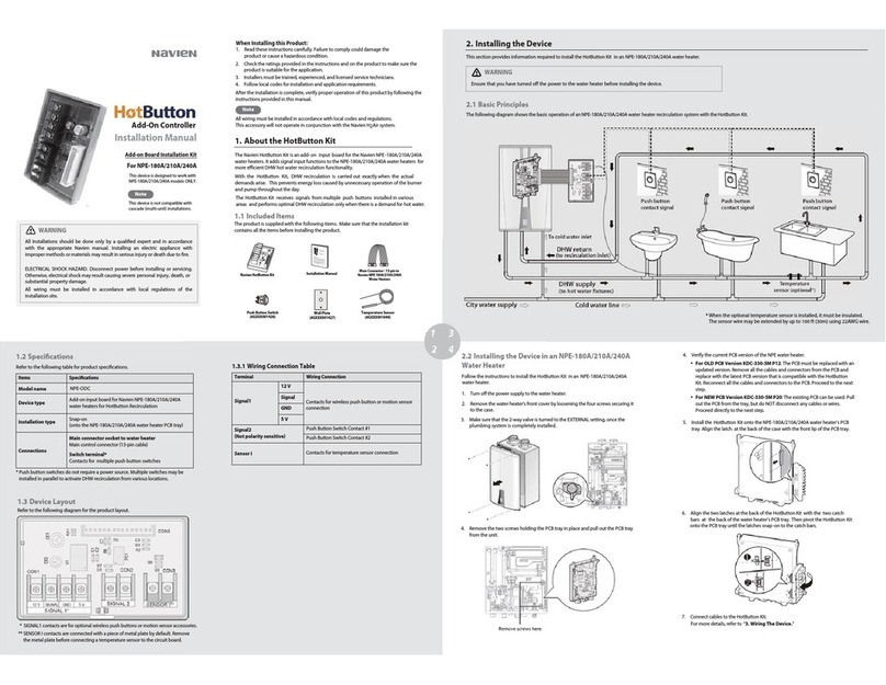
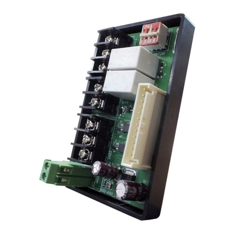
Navien H2Air User manual

Installation Manual
Add-on Controller Installation Kit
NPE-A all models
NPE-A2/S2 all models
NPN all models
This device is designed to work
with NPE-A, NPE-A2/S2, and NPN
water heaters only.
WARNING
All Installations should be done only by a qualified expert and in accordance
with the appropriate Navien manual. Installing an electric appliance with
improper methods or materials may result in serious injury or death due to
fire.
ELECTRICAL SHOCK HAZARD. Disconnect power before installing or
servicing. Otherwise, severe personal injury, death, or substantial property
damage may result.
All wiring must be installed in accordance with local regulations of the
installation site.

When Installing this Product:
1.
Read these instructions carefully. Failure to follow them could damage the
product or cause a hazardous condition.
2.
Check the ratings given in the instructions and on the product to make sure
the product is suitable for the application.
3.
Installers must be trained, experienced, and licensed service technicians.
4.
Follow local codes for installation and application.
After installation is complete, check the product’s operation by following the
instructions provided in this manual.
All wiring must be installed in accordance with local regulations of the installation
site.
Note

Contents
3
Contents
1. About the H2Air 5
1.1 Included Items 5
1.2 Specifications 6
1.3 Device Layout 6
1.3.1 Wiring Connection Table 7
1.3.2 Dip Switch Function Table 7
2. Installing the Device 8
2.1 Basic Principles 8
2.2 Installing the Device in Water Heaters 11
3. Wiring the Device 14
3.1 System Wiring Examples 14
3.1.1 1-Stage Thermostat / 2-Stage Control Heating System 14
3.1.2 1-Stage Thermostat / 1-Stage Control Heating System 15
3.1.3 2-Stage Thermostat / 2-Stage Control Heating System 15
3.1.4 Configuring the Cooling System (for a Heating / Cooling Combo System) 16
3.2 Cable Connections 17
3.2.1 Connecting the Outdoor Temperature Sensor Cable 17
3.2.2 Connecting the Thermostat Cables 18
3.2.3 Connecting the Flow Switch Cables 18
3.2.4 Connecting the Main Control Connector 19
4. Configuring the Device 20
4.1 System Air Removal 20
4.2 Pump Control Options 20
4.3 DHW Priority Options 23
4.3.1 DHW Priority Mode 23
4.3.2 Simultaneous DHW and Space Heating Mode 23
5. Parameter Table 24
5.1 NPE-A and NPN Parameter Table 24
5.2 NPE-A2/S2 Parameter Table 25
5.2.1 Parameter Settings 25
5.2.2 Application Settings 26

About the H
2
Air
5
1.
About the H
2
Air
Navien H
2
Air is an add-on controller for the Navien water heaters. It adds input
and output functions to the water heaters for a combination application where
space heating and domestic hot water (DHW) are supplied simultaneously. With
this add-on controller, a thermostat (1 or 2-stage) and an outdoor sensor can be
installed along with a hydronic air handler to add space heating functionality to
the system.
1.1
Included Items
The product is supplied with an installation kit. Make sure that the installation kit
contains the following items before installing the product.
Navien H
2
Air
Add-on Controller
Installation Manual
Main Control Connector
(13-pin cable for connection to
water heaters)
Outdoor Temperature Sensor (with
cable)
Flow Switch (with cable)

6
About the H
2
Air
1.2
Specifications
Refer to the following table for product specifications.
Items
Specifications
Model name
KDO-A100
Device type
Add-on controller for Navien water heaters
Installation type
Snap-on
(onto the water heater PCB tray)
Connections
Main connector socket to water heater
Main control connector (13-pin cable)
Thermostat input terminals
Contacts for one thermostat (1 or 2-stage)
Outdoor sensor connection terminal
Contacts for one outdoor sensor
Output terminal to the air handler unit
Contacts for one AHU (1 or 2-stage)
1.3
Device Layout
Refer to the following diagram for the product layout.

About the H
2
Air
7
1.3.1
Wiring Connection Table
Terminal
Wiring Connection
AHU W1
Connect to AHU W1
AHU W2
Connect to AHU W2
AHU R
Connect to AHU R
Flow switch
Flow switch input terminal
T/S W1
Connect to thermostat W1
T/S W2
Connect to thermostat W2
T/S R
Connect to thermostat R
Outdoor Sensor
Outdoor sensor input
1.3.2
Dip Switch Function Table
SW (DIP 1–4)
ON
OFF
Default
DIP 1
Outdoor reset not in use
Outdoor reset in use
OFF
DIP 2
Simultaneous DHW and
heating*
DHW priority
OFF
DIP 3
2-stage thermostat using
1-stage thermostat using
OFF
DIP 4
Reserved
OFF
* Depending on the DHW flow rate (demand), simultaneous DHW and heating may not be
available. When the DHW demand is high, DHW supply takes priority and the heating may be
temporarily turned off until the DHW demand decreases, even when this function is activated.

8
Installing the Device
2.
Installing the Device
This section provides information required to install the H
2
Air add-on controller in
water heaters.
WARNING
Ensure that you have turned off the power to the water heater before installing
the device.
2.1
Basic Principles
The following diagram shows the basic operation of water heaters with the H
2
Air
add-on controller.
System Diagram for NPE-A

Installing the Device
9
System Diagram for NPE-A2
System Diagram for NPE-S2

10
Installing the Device
System Diagram for NPN
WARNING
A mixing valve must be installed in the system in order to limit the DHW output
temperature and prevent scalding. Setting the mixing valve to 115–120
℉
is
recommended.
Install a spring check valve for vertical pipe runs. Do not use a swing check
valve with vertical piping.
Install either a spring check valve or a swing check valve in a horizontal pipe
run.
An outdoor sensor and a flow switch are supplied with the product.
Use 18 AWG cables for thermostat wiring.
When using an external pump, connect the pump to the water heater PCB
directly using a Navien External Pump Cable (GXXX001319).
Note

Installing the Device
11
2.2
Installing the Device in Water Heaters
Follow the instructions to install the Navien H
2
Air in water heaters.
1.
Turn off the power supply to the water heater.
2.
Remove the water heater’s front cover by loosening the four screws securing
it to the case.
3.
For NPE-A:
Remove the two screws holding the PCB tray in place and pull out the PCB
tray from the unit.

12
Installing the Device
4.
Install the H
2
Air onto the water heater’s PCB tray. Align the latch at the back of
the case with the front lip of the PCB tray.
5.
Align the two latches at the back of the H
2
Air with the two catch bars at the
back of the water heater’s PCB tray. Then pivot the H
2
Air onto the PCB tray
until the latches snap-on to the catch bars.
Replace the PCB tray back into the water heater and secure it with the two
screws.
For NPE-A2/S2:
Remove the existing HotButton controller from its mounted location and replace
it with the H
2
Air controller using the provided tabs on the component housing.

Installing the Device
13
For NPN:
Remove the screws holding the front panel to the bracket to pull out the part.
Attach the H
2
Air controller on the back side of the Front Panel at the
designated mounting location by using the provided tabs on the component
housing.
6.
Connect all cables and wiring to the H
2
Air. For more details, refer to “3.2 Cable
Connections”, on page 17.
7.
Set the proper DIP switches for the desired installation setup. For more
details, refer to “1.3.2 Dip Switch Function Table“, on page 7.
8.
Make sure to replace the PCB or front panel back into the water heater and
secure it with the two screws.
9.
Close the front cover and secure it with the 4 screws.
CAUTION
Before disconnecting cables inside the unit, label all cables. Wiring errors can
cause improper operation and dangerous situations. Verify wiring
connections and unit operation after servicing.

14
Wiring the Device
3.
Wiring the Device
This section provides information required to plan and install the system wiring.
3.1
System Wiring Examples
Refer to the following wiring diagrams to properly install wiring for various setups
you may need in your system. Set DIP switch (SW) #3 as specified for each
configuration.
3.1.1
1-Stage Thermostat / 2-Stage Control Heating System
Set DIP switch (SW) #3 to ‘Off’ to configure the system to use a 1-stage
thermostat/ 2-stage control.

Wiring the Device
15
3.1.2
1-Stage Thermostat / 1-Stage Control Heating System
Set DIP switch (SW) #3 to ‘Off’ to configure the system to use a 1-stage thermostat
/ 1-stage control.
3.1.3
2-Stage Thermostat / 2-Stage Control Heating System
Set DIP switch (SW) #3 to ‘On’ to configure the system to use a 2-stage thermostat
/ 2-stage control.

16
Wiring the Device
3.1.4
Configuring the Cooling System (for a Heating / Cooling
Combo System)
To configure the cooling system, connect the thermostat
Y
terminal to the AHU
cooling input terminal
Y
, and connect the thermostat
R
terminal to the
AHU R
output.

Wiring the Device
17
3.2
Cable Connections
Follow the instructions below to connect the cables to the H
2
Air.
3.2.1
Connecting the Outdoor Temperature Sensor Cable
An outdoor temperature sensor is supplied with the Navien H
2
Air installation kit.
Insert the exposed wire into the terminal. Then tighten the terminal screw with a
screwdriver.
Use thermostat wire (18 gauge wire) for the outdoor temperature sensor
connection.
When installing the outdoor temperature sensor, avoid installing it in direct
sunlight.
Note

18
Wiring the Device
3.2.2
Connecting the Thermostat Cables
The H
2
Air receives input signals from thermostats to control the AHU. Insert the
wiring or connector into the contact. Then tighten the terminal screw with a
screwdriver.
3.2.3
Connecting the Flow Switch Cables
Insert the fork connectors into the contact. Then tighten the terminal screw with a
screwdriver.

Wiring the Device
19
3.2.4
Connecting the Main Control Connector
To connect the H
2
Air to the Navien water heaters, use the 13-pin main control
connector supplied with the Navien H
2
Air. Connect one end of the cable to the
connector socket on the H
2
Air PCB. Then, connect the other end to the connector
socket on the water heater PCB.
For NPN only
- Make sure to use the included extended 13-pin cable for sufficient
length from the PCB.
Note

20
Configuring the Device
4.
Configuring the Device
This section provides the information required to set the desired options for the
Navien water heater system with the H
2
Air add-on controller.
4.1 System Air Removal
Make sure to remove all excess air from the combination system piping. To
assist with this process, the NPE and NPE-A2/S2 Series water heater models
have an available TEST MODE feature (see below).
For NPE and NPE-A2/S2 - Enter the Special Operations menu to access the
TEST MODE feature by pressing the [Diagnostic] and [Back] buttons. Choose
TEST MODE, then PUMP to allow the unit to cycle the internal pump. This
process will assist in removing the remaining air from the system piping by
either using the provided air vent on the internal pump or optional air
removal accessories installed on the system piping.
4.2
Pump Control Options
CAUTION
The drawings in this instruction are intended only as a guide and are not
replacements for professional engineering drawings. This drawing represents
a concept system and does not imply compliance with local building codes.
Actual installation requirements may vary depending on installation locations
and parameters. All installation work must be carried out in accordance with
all local building codes. Verify with local building officials before commencing
system installation.
The following example demonstrates the application of pump control
configuration options.
Table of contents
Other Navien Controllers manuals
Popular Controllers manuals by other brands

Honeywell
Honeywell 7800 SERIES manual

Rockwell Automation
Rockwell Automation Allen-Bradley 1769-OA16 installation instructions

YASKAWA
YASKAWA YRC1000 SAFETY REQUIREMENTS

tbs electronics
tbs electronics Omnicharge Solar OCS 100-20 installation manual

BIFFI
BIFFI ICON3000 Series Service manual

Fenwal Controls
Fenwal Controls 35-70 Series quick start guide