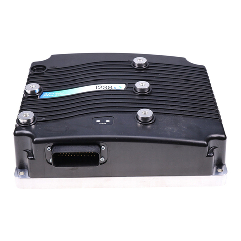
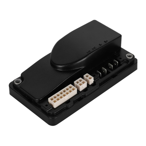
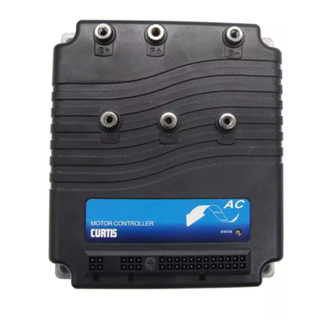
Curtis Instruments F Series User manual

Read Instructions Carefully!
Specications are subject to change without notice.
© 2020 Curtis Instruments, Inc. ® Curtis is a registered trademark of Curtis Instruments, Inc.
© The design and appearance of the products depicted herein are the copyright of Curtis Instruments, Inc. 53234, RevA August 2020
Curtis Instruments, Inc.
200 Kisco Avenue
Mt. Kisco, NY 10549
www.curtisinstruments.com
Manual
F Series Motor Controller
With VCL
For Controllers: AC F4-A Model
» Software Device Profile: 2.4.x.x «

Curtis AC F4-A Motor Controller – August 2020
pg. ii
CHAPTERS
1: OVERVIEW ...................................................................................................................................... 1
HOW TO USE THIS MANUAL .......................................................................................................... 2
GETTING THE MOST OUT OF YOUR CURTIS CONTROLLER ............................................................. 2
2: INSTALLATION AND WIRING ............................................................................................................ 3
PHYSICALLY MOUNTING THE CONTROLLER................................................................................... 3
PRECAUTIONS .............................................................................................................................. 4
HIGH CURRENT CONNECTIONS ..................................................................................................... 4
LOW CURRENT CONNECTIONS...................................................................................................... 6
ROTOR POSITION FEEDBACK (PINS 18, 26, 31, 32) ................................................................. 7
CANBUS (PINS 21, 34 AND 28, 29).......................................................................................... 7
ALL OTHER LOW POWER WIRING............................................................................................ 7
PROTECTED VOLTAGES........................................................................................................... 8
CONTROLLER INPUTS AND OUTPUTS...................................................................................... 9
CONTROLLER WIRING DIAGRAM (EXAMPLES) ........................................................................ 10
LOW CURRENT 35-PIN CONNECTOR ELECTRICAL SPECIFICATIONS ....................................... 13
DIGITAL (SWITCH) INPUTS ..................................................................................................... 13
ANALOG INPUTS.................................................................................................................... 15
POTENTIOMETER INPUTS WITH DYNAMIC TESTING................................................................ 16
PWM AND DIGITAL DRIVERS .................................................................................................. 17
POWER SUPPLY OUTPUTS ..................................................................................................... 19
KEYSWITCH AND COIL SUPPLY .............................................................................................. 20
CAN PORTS........................................................................................................................... 21
MOTOR POSITION SENSOR INPUTS ....................................................................................... 22
MOTOR TEMPERATURE INPUT ............................................................................................... 24
TABLE OF CONTENTS

Curtis AC F4-A Motor Controller – August 2020 pg. iii
TABLE OF CONTENTS cont’d
3: APPLICATION-SPECIFIC FEATURES................................................................................................. 25
MOTOR SPEED CONSTRAINTS ..................................................................................................... 25
VOLTAGE LIMITS .......................................................................................................................... 26
OVER-VOLTAGE REGION......................................................................................................... 27
SEVERE OVER-VOLTAGE REGION............................................................................................ 27
UNDER-VOLTAGE REGION ...................................................................................................... 27
OUTPUT-DISABLED REGION................................................................................................... 28
BROWNOUT VOLTAGE ............................................................................................................ 28
BATTERY DISCHARGE INDICATOR................................................................................................. 28
4: PROGRAMMABLE PARAMETERS .................................................................................................... 29
PROGRAMMABLE PARAMETERS .................................................................................................. 29
PROGRAMMING MENUS............................................................................................................... 29
PARAMETER CHANGE FAULTS [PCF]............................................................................................. 29
MONITOR VARIABLES WITHIN PARAMETER MENUS ...................................................................... 29
PROGRAMMING TOOLS................................................................................................................ 29
MENU CHART FORMAT ................................................................................................................ 30
TERMINOLOGY ............................................................................................................................ 30
SDO WRITE MESSAGE.................................................................................................................. 32
PARAMETER MENUS.................................................................................................................... 33
SPEED MODE EXPRESS ......................................................................................................... 40
SPEED MODE ........................................................................................................................ 41
APPLICATION SETUP.................................................................................................................... 48
CONTROLLER SETUP ................................................................................................................... 85
AC MOTOR SETUP MENU............................................................................................................ 109

Curtis AC F4-A Motor Controller – August 2020
pg. iv
TABLE OF CONTENTS cont’d
5: SYSTEM MONITOR........................................................................................................................ 116
6: COMMISSIONING .......................................................................................................................... 127
INITIAL SETUP ............................................................................................................................ 127
TO BEGIN ............................................................................................................................. 128
CONTROL MODE SELECTION ................................................................................................ 128
PARAMETER SETTINGS – METHOD OVERVIEW...................................................................... 128
AC TRACTION MOTOR SETUP GUIDE..................................................................................... 129
CONTROLLER SETUP GUIDE ................................................................................................. 131
TRACTION THROTTLE SETUP................................................................................................ 133
VOLTAGE THROTTLE ............................................................................................................. 136
AUTOMATED ACIM (MOTOR) CHARACTERIZATION PROCEDURE ................................................... 142
TRACTION SYSTEMS................................................................................................................... 143
TUNING GUIDE............................................................................................................................ 147
SELECTING THE CONTROL MODE ......................................................................................... 147
0 − SPEED MODE EXPRESS TUNING..................................................................................... 147
1 − SPEED MODE TUNING .................................................................................................... 148
OTHER PARAMETER TUNING................................................................................................. 149
SETTING UP THE HYDRAULIC SYSTEM ........................................................................................ 150
HYDRAULIC LIFT AND LOWER COMMAND INPUTS....................................................................... 150
LIFT & LOWER SWITCH INPUTS ............................................................................................ 151
LIFT SWITCH INPUT, WITH A PROPORTIONAL LOWERING VALVE............................................. 153
7: DIAGNOSTICS AND TROUBLESHOOTING........................................................................................ 155
THE DIAGNOSTICS PROCESS ...................................................................................................... 155
TROUBLESHOOTING CHART INDEX.............................................................................................. 160
FAULT ACTIONS .......................................................................................................................... 164
8: MAINTENANCE ............................................................................................................................. 183
CLEANING................................................................................................................................... 183
FAULT HISTORY........................................................................................................................... 183

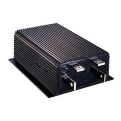
TABLE OF CONTENTS cont’d
Curtis AC F4-A Motor Controller – August 2020 pg. v
APPENDIX A...................................................................................................................................... 184
CANOPEN PDO MAPPING OBJECT DESCRIPTION......................................................................... 184
EXAMPLE FOR RPDO MAPPING WITH THE CIT CIT PROGRAMMER ............................................... 186
EXAMPLE FOR TPDO MAPPING WITH THE PROGRAMMER............................................................ 188
EXAMPLE FOR RPDO MAPPING WITH SDO WRITES...................................................................... 189
APPENDIX B ..................................................................................................................................... 191
ELECTROMAGNETIC COMPATIBILITY (EMC) ................................................................................. 191
ELECTROSTATIC DISCHARGE (ESD) IMMUNITY ............................................................................ 192
DECOMMISSIONING AND RECYCLING THE CONTROLLER............................................................. 192
APPENDIX C ..................................................................................................................................... 193
EN 13849 COMPLIANCE ............................................................................................................. 193
APPENDIX D ..................................................................................................................................... 195
CURTIS INTEGRATED TOOLKITTM.................................................................................................. 195
CREATING A PROJECT WITH A NEW F-SERIES CONTROLLER................................................. 197
VEHICLE CAN-PORT WIRING........................................................................................................ 204
APPENDIX E...................................................................................................................................... 205
SPECIFICATIONS: CONTROLLER .................................................................................................. 205

Curtis AC F4-A Motor Controller – August 2020
pg. vi
TABLES
TABLE 1: HIGH POWER CONNECTIONS................................................................................................ 4
TABLE 2: THE AMPSEAL CONNECTOR COMPONENTS & PART NUMBERS............................................. 6
TABLE 3: AMPSEAL CONNECTIONS PROTECTED VOLTAGES ................................................................ 8
TABLE 4: LOGIC AND LOW-CURRENT CONNECTIONS .......................................................................... 9
TABLE 5: SWITCH (DIGITAL) INPUTS ELECTRICAL SPECIFICATIONS..................................................... 13
TABLE 6: ANALOG INPUTS ELECTRICAL SPECIFICATIONS ................................................................... 15
TABLE 7: POTENTIOMETER INPUT/CONFIGURATION ELECTRICAL SPECIFICATIONS ............................. 17
TABLE 8: DRIVER OUTPUTS ELECTRICAL SPECIFICATIONS.................................................................. 18
TABLE 9: POWER-SUPPLY OUTPUTS ELECTRICAL SPECIFICATIONS .................................................... 19
TABLE 10: KEYSWITCH AND COIL SUPPLY ELECTRICAL SPECIFICATIONS............................................ 20
TABLE 11: CAN PORTS ELECTRICAL SPECIFICATIONS ........................................................................ 21
TABLE 12: DIGITAL/QUADRATURE ENCODER ELECTRICAL SPECIFICATIONS ........................................ 22
TABLE 13: SIN/COS SENSOR DEVICE ELECTRICAL SPECIFICATIONS ................................................... 23
TABLE 14: MOTOR TEMPERATURE SENSOR SPECIFICATIONS............................................................. 24
TABLE 15: PROGRAMMABLE PARAMETERS MENUS: CURTIS INTEGRATED TOOLKITTM/1313 HHP ........ 33
TABLE 16: SYSTEM MONITOR VARIABLES ........................................................................................ 116
TABLE 17: FAULT ACTIONS................................................................................................................ 164
TABLE 18: FAULT CODE TROUBLESHOOTING CHART ......................................................................... 166
TABLE E-1: SPECIFICATIONS: AC F4-A CONTROLLER......................................................................... 205
TABLE OF CONTENTS cont’d

pg. vii
FIGURES
FIGURE 1: AC F4-A MOTOR CONTROLLER ........................................................................................... 1
FIGURE 2: AC F4-A DIMENSIONS......................................................................................................... 3
FIGURE 3: BATTERY POWER AND MOTOR PHASE TERMINAL CONNECTIONS........................................ 5
FIGURE 4: 35-PIN AMPSEAL CONNECTOR ........................................................................................... 6
FIGURE 5: 35-PIN AMPSEAL CONNECTION ASSIGNMENTS .................................................................. 7
FIGURE 6: AC F4-A BASIC WIRING DIAGRAM ...................................................................................... 10
FIGURE 7: AC F4-A CAN TILLER HEAD WIRING DIAGRAM .................................................................... 11
FIGURE 7A: AC F4-A ISOLATED CAN .................................................................................................. 12
FIGURE 8: ACCELERATION RATE RESPONSE ....................................................................................... 44
FIGURE 9: BRAKING RESPONSE RATE................................................................................................. 45
FIGURE 10: THROTTLE ADJUSTMENTS DIAGRAM .............................................................................. 50
FIGURE 11: THROTTLE SIGNAL PROCESSING ..................................................................................... 52
FIGURE 12: BRAKE SIGNAL PROCESSING ........................................................................................... 55
FIGURE 13: EMERGENCY REVERSE SUPERVISION FUNCTION.............................................................. 70
FIGURE 14: INTERLOCK BRAKE SUPERVISION SPEED LIMIT FOR POSITIVE INITIAL SPEED................... 72
FIGURE 15: INTERLOCK BRAKE SUPERVISION SPEED LIMIT FOR NEGATIVE INITIAL SPEED ................. 73
FIGURE 16: INTERLOCK BRAKE SUPERVISION DISTANCE CHECK ........................................................ 73
FIGURE 17: HYDRAULIC SYSTEM DIAGRAM, WITH LOAD-HOLD A
ND PROPORTIONAL LOWER VALVES............................................................................. 75
FIGURE 18: HYDRAULIC SYSTEM DIAGRAM, WITH A FIXED (ON/OFF) LOAD-HOLD VALVE..................... 76
FIGURE 19: LIFT-INPUT SIGNAL CHAIN (PROCESSING) ....................................................................... 77
FIGURE 20: LIFT-LOWERING SIGNAL CHAIN (PROCESSING)................................................................. 77
FIGURE 21: INPUT 10 DIGITAL AND ANALOG SIGNAL CHAIN................................................................ 87
FIGURE 22: DRIVE CURRENT LIMITING MAP ...................................................................................... 107
FIGURE 23: REGEN CURRENT LIMITING MAP..................................................................................... 108
FIGURE 24: THROTTLE RELATED PARAMETERS – SETUP OPTIONS.................................................... 134
TABLE OF CONTENTS cont’d
Curtis AC F4-A Motor Controller – August 2020

pg. viii
TABLE OF CONTENTS cont’d
FIGURE 25: WIRING FOR 3-WIRE POTENTIOMETER THROTTLES ........................................................ 135
FIGURE 26: WIRING FOR 2-WIRE POTENTIOMETER THROTTLES ........................................................ 136
FIGURE 27: CURTIS FP-SCV-0022 HALL-EFFECT THROTTLE.............................................................. 137
FIGURE 28: WIRING FOR VOLTAGE TYPE THROTTLES ......................................................................... 138
FIGURE 29: THE PROPORTIONAL VALVE SIGNAL CHAIN...................................................................... 151
FIGURE 30: THE LOAD HOLD VALVE SIGNAL CHAIN ........................................................................... 151
FIGURE 31: CURTIS INTEGRATED TOOLKITTM PROGRAMMER PRESENT
AND FAULT HISTORY SEQUENCE EXAMPLE................................................................. 156
FIGURE C-1: SUPERVISORY SYSTEM IN THE CURTIS AC MOTOR CONTROLLER.................................. 193
Curtis AC F4-A Motor Controller – August 2020

1 — OVERVIEW pg. 1
Return to TOC Curtis AC F4-A Motor Controller – August 2020
1 — OVERVIEW
e AC F4-A is CAN-based induction-motor controller. Available in either 24 volt or 36-48 volt
models, this compact motor controller delivers unmatched performance with a exible feature set.
e Model AC F4-A is fully optimized for use as a traction controller on class III pedestrian-operated
powered pallet trucks. It provides vehicle designers with the ability to fully dene and control the
detailed dynamic performance of their vehicle’s drivetrain, and also provides comprehensive vehicle
management and CAN manager capabilities. Model AC F4-A is also suitable for traction or hydraulic
pump control on other types of battery powered vehicles.
Together with the new Curtis model 3140/3141 CAN LCD display and the new user-friendly Curtis
Integrated ToolkitTM, the Curtis model AC F4-A is the ultimate Class III truck control system.
Easily enhance any application by using Curtis’s Vehicle Control Language (VCL). e F4’s setup and
diagnostic tasks use the new PC-based Curtis Integrated Toolkit™ program (CIT) or the CAN-based
Curtis 1313 handheld programmer (1313HHP).
Figure 1
AC F4-A Motor
Controller

1 — OVERVIEW
Curtis AC F4-A Motor Controller – August 2020 Return to TOC
pg. 2
HOW TO USE THIS MANUAL
is manual describes how to:
• Properly mount and wire the F4-A controller
• Understand the congurable inputs and outputs
• Apply specic features to match an application
• Access and change parameters
• View and use monitor variables
• Preform the initial setup
• Setup the PDO Mapping
• Diagnose and troubleshoot faults
• Select and use the available programming and diagnostic tools
GETTING THE MOST OUT OF YOUR CURTIS CONTROLLER
Thoroughly read and refer to this manual to apply and configure the F4-A controller.
Understanding the installation & wiring guidelines, the parameter settings, the VCL functions,
the initial setup & commissioning, and using the diagnostic and troubleshooting guide are critical
to a successful application.
This manual describes the typical usage of the F4-A controller. If the intended application is
not illustrated or discussed within this manual, contact the Curtis distributor or the regional
Curtis sales-support oce for additional technical support. e Curtis sales and support oce-
contact information is available from the Curtis Instruments website under the International tab.
https://www.curtisinstruments.com/international/
3141 CAN Gauge

2 — INSTALLATION AND WIRING pg. 3
Return to TOC Curtis AC F4-A Motor Controller – August 2020
2 — INSTALLATION AND WIRING
PHYSICALLY MOUNTING THE CONTROLLER
Use Figure 2, the F4’s outline and mounting-hole dimensions, to determine the optimum mounting
location. Properly installed, the controller meets the IP65 requirements for environmental protection
against dust and water. Nevertheless, in order to prevent external corrosion and leakage paths from
developing, choose a mounting location to keep the controller as clean and dry as possible. Protect
all ends of the low-power (signal) harness from excessive moisture and water (e.g., any toggle switch,
sensor, and device connections on the vehicle).
Mount the controller to a at surface devoid of protrusions, ridges, or a curvature that can cause damage
or distortion to its heatsink (base plate). Secure the controller using evenly torqued bolts to the vehicle’s
mounting surface. Applying a thin layer of thermal joint compound improves heat conduction from
the controller heatsink to the vehicle’s mounting surface. Typically, when properly mounted to a larger
(smooth) metal surface, an additional heatsink or cooling fan is not necessary to meet the application’s
peak and continuous current ratings.
Figure 2
AC F4-A dimensions
5X M6X 1.0 - 6H 18 MIN
4X ø 7.0 169.0
180.0
5.5 5.5
129.0 140.0
STATUS LED
74.0 75.0
12.0
Dimensions are in millimeters

2 — INSTALLATION AND WIRING
Curtis AC F4-A Motor Controller – August 2020 Return to TOC
pg. 4
HIGH CURRENT CONNECTIONS
ere are ve high-current connections identied on the controller cover as B+, B–, U, V, and W.
Install the controller with a (main) contactor between the traction battery positive terminal and the
B+ terminal. is wiring circuit shall also be tted with a fuse (the fuse amperage rating to match
the application).
Terminal Function
B+ Positive Battery to Controller
B– Negative Battery to Controller
UMotor Phase U
VMotor Phase V
WMotor Phase W
Table 1 High Power Connections
Working on electrical systems is potentially dangerous. Protect personnel and property
against uncontrolled operation, high current arcs, and outgassing from lead-acid batteries:
UNCONTROLLED OPERATION — Some conditions could cause the motor to run out of control.
Disconnect the motor or jack up the vehicle and get the drive wheels off the ground before
attempting any work on the motor control circuitry.
HIGH CURRENT ARCS — Batteries can supply very high power, and arcing can occur if the
terminals are short-circuited. Always open the battery circuit before working on the motor
control circuit. Wear safety glasses, and use properly insulated tools to prevent shorts.
LEAD-ACID BATTERIES — Charging or discharging generates hydrogen gas, which can build
up in and around the batteries. Follow the battery manufacturer’s safety recommendations.
Wear safety glasses when servicing, charging and working around the battery.
LITHIUM ION BATTERIES — Follow the battery manufacturer’s “safety precautions for the
Lithium Ion battery pack.” Wear safety glasses when servicing, charging and working around
the battery.
CAUTION
PRECAUTIONS
Take the steps during the application’s design and development to ensure that the EMC performance
complies with applicable regulations; Appendix B presents some design considerations for
EMC mitigation.

2 — INSTALLATION AND WIRING pg. 5
Return to TOC Curtis AC F4-A Motor Controller – August 2020
e high power connections are aluminum M6 terminals. Terminate the battery and motor cables
with high quality (tin-plated) copper lugs to match the application. Ensure the M6 bolts are the
proper length to meet the minimum thread depth engagement. Do not bottom-out the bolts in any
terminal. Follow Figure 3 connection guidelines:
• Place the lug on top of the aluminum terminal, followed by a high-load safety washer with its
convex side on top. e washer should be a SCHNORR 416320, or equivalent.
• For terminal connections with more than one lug, stack them so the lug carrying the least
current is on top.
• Ensure the clamping bolt is within the minimum and maximum depth when assembled.
• Tighten the assembly to 10.2 ±1.1 Nm (90 ±10 in-lbs.).
When routing the battery cables between the battery and controller, run the positive and negative
battery cables close to each other, avoiding pinch-points and areas of possible cable abrasion.
Typically, the positive cable is red and the negative cable is black. e motor phase cables are oen
black, yet clearly labeled at both ends. Reference Appendix B, Vehicle Design Considerations for
EMC guidelines.
Figure 3
Battery Power
and Motor
Phase Terminal
Connections
M6 BOLT
HIGH LOAD
SAFETY WASHER
LUG
M6 TERMINAL
SECTION VIEW
F4-A TERMINALS
EXPLODED VIEW
10 mm MIN
DEPTH
18 mm MAX
DEPTH

2 — INSTALLATION AND WIRING
Curtis AC F4-A Motor Controller – August 2020 Return to TOC
pg. 6
LOW CURRENT CONNECTIONS
All logic and low power connections are through a single 35-pin AMPSEAL connector (mold in
the cover) utilizing gold-plated pins. e matching AMPSEAL receptacle’s wire silos come sealed
by a membrane. Pierce the membrane by inserting the individual terminated wires. To maintain the
IP65 rating, use the proper wire gauge and insulation thickness. Seal any non-used wire positions
that have their silo-diaphragm pierced with the specic AMPSEAL sealing plug. Do not mix gold
and tin pin types.
• Figure 4 shows the AMPSEAL receptacle (plug) housing. Note the molded-in silo numbering.
• Figure 5 illustrates the connection assignments (as the plug aligns with the controller).
• Table 2 lists the matching AMPSEAL vehicle-harness component part numbers.
Figure 4
35-Pin AMPSEAL
Connector
13
24
1
23
35
12
AMPSEAL 35 PIN Connector Harness-side view
Note: e silo numbers are molded on the top and sides of the AMPSEAL connector receptacle (plug).
Table 2 The AMPSEAL Connector Components & Part Numbers
Matching AMPSEAL 35-pin Component* Part Number
AMPSEAL receptacle housing (the black vehicle-harness plug) 776164-1
Plug’s gold-plated socket terminals (strip form p/n) 770520-3
Plug’s gold-plated socket terminals (loose piece p/n) 770854-3
Silo seal plug (for non-used pin positions with a pierced membrane) 770678-1
Plug’s tin-plated socket terminals (strip form p/n) 770520-1
Plug’s tin-plated socket terminals (loose piece p/n) 770854-1
Harness wire size (gauge) 0.5 – 1.25 mm2
(20 – 16 AWG)
Wire diameter (overall) [i.e., uses wire with thin-wall insulation] 1.7 – 2.7 mm
Hand Crimper for the wire-harness socket terminals 58440-1
*AMPSEAL components and tooling are available worldwide from multiple TE Connectivity electrical component distributors.
Reference the TE Connectivity Document: Application Specification 114-16016.
http://www.te.com/commerce/DocumentDelivery/DDEController
TE Connectivity website: http://www.te.com/usa-en/products/connectors/automotive-connectors/intersection/ampseal-connectors.html

2 — INSTALLATION AND WIRING pg. 7
Return to TOC Curtis AC F4-A Motor Controller – August 2020
35 34 33 32 31 30 29 28 27 26 25 24
12 11 10 9 8 7 6 5 4 3 2 1
23 22 21 20 19 18 17 16 15 14 13
CAN1 L
CAN 1
TERM L
CAN1 H
INPUT 8
INPUT 4
ENC 1B
INPUT 3
ENC 1A
DRIVER 8
CAN2 L
CAN2 H
INPUT 19
POT 19 SUPPLY
INPUT 31
+5V SUPPLY
INPUT 14
+12V SUPPLY
INPUT 9
KSI
DRIVER 1
INPUT 21
DRIVER 4
INPUT 24
DRIVER 3
INPUT 23
DRIVER 2
INPUT 22
DRIVER 5
INPUT 25
GND
INPUT 2
MOTOR TEMP
INPUT 5
INPUT 10
(PWM)
INPUT 11
ENC 1C
INPUT 12
ENC 2A
INPUT 7
CAN 1
TERM H
DRIVER 7
INPUT 27
DRIVER 6
INPUT 26
GND
INPUT 18
POT 18 WIPER
INPUT 1
POT 1 WIPER
INPUT 6
POT 6 SUPPLY
INPUT 13
ENC 2B
COIL
SUPPLY
ISOLATED GROUND
MODELS w/ Isolated CAN
NOT USED ON
MODELS w/ Isolated CAN
Figure 5
35-Pin AMPSEAL
Connection Assignments
e 35-pin Input and Outputs (I/O) assignments in Figure 5 follow the basic wiring diagram of Figure 6.
Figure 5’s orientation is looking at the controller, which is also the harness-side of the connector. When
designing a vehicle harness and its routing throughout a vehicle, follow these guidelines to avoid common
control-signal interference. Protect the wiring from abrasions due to vibrations, pinch, cut and pull-lose
damage, which can lead to an inoperative controller. Reference Appendix B, Vehicle Design Considerations
for EMC guidelines.
Rotor Position feedback (Pins 18, 26, 31, 32)
e rotor-position sensor’s wiring (+5V, Feedback A, Feedback B, and Ground) should be bundled together
between the motor and controller. ese wires are oen run with the rest of the low current wiring harness
without interference issues, but the encoder wires should not be routed near the motor cables. In applications
where this is not possible or there is signal interference, twist the encoder signal wires. In cases using a
shielded cable (e.g., shielded 2-wire twisted-pair with drain-wire), only ground the shield-drain wire at the
controller ground (pin 18).
CANbus (Pins 21, 34 and 28, 29)
Use twisted-pair wires for the CANbus connections. Keep the CAN wiring away from the high current cables
and cross them at right angles when necessary. In extreme cases, use shielded cable with the shield connected
to the ground (pin 7) only on the controller side for the non-isolated controller models.
Two CAN ports allow the implementation of both 11-bit identiers (CANopen) and 29-bit identiers (e.g.,
J1939), and/or dierent baud rates to support a high-speed CANbus for safety or data logging.
An isolated CAN option uses a separate (isolated) CANbus ground reference, which is useful on vehicles with
CANbus systems operating at dierent battery voltages. It avoids common mode noise issues. e isolated
ground (pin 34) is provided for twisted pair shielding, and may not be needed. When using shielded wiring,
only connect the shield’s drain-wire to pin 34. e option always includes both CAN1 and CAN2 as isolated
CAN.

2 — INSTALLATION AND WIRING
Curtis AC F4-A Motor Controller – August 2020 Return to TOC
pg. 8
All other low power wiring
Use standard vehicle-harness routing practices for the remaining connections. When designing the
vehicle’s wiring and routing, keep the inputs such as the throttle, temperature, and the motor feedback
signals separate from controller’s output lines such as the coil driver outputs. Avoid routing the low-
power wiring parallel to the high power (and high current) battery and motor cables.
Protected voltages
e low-power pins’ protected voltage ratings listed in Table 3 are absolute and are not for normal
operation. To prevent damage to the controller, do not connect (i.e., short circuit) the Coil Supply
(pin 13) to battery negative. Further, do not connect (i.e., short circuit) the I/O Ground (pins 7 &
18) to battery positive.
Table 3 AMPSEAL Connections Protected Voltages
Controller I/O
Pin Number
Min (reverse)
Voltage
Maximum
Voltage
ESD
Air Discharge
(non-contact)
Contact
(touch)
Inputs
8, 9, 10, 11, 12, 14, 15, 16, 17, 22, 24, 25,
26, 27, 31, 32, 33
Indenite short to B+ and B–
±15kV ±8kV
CAN (non-isolated)
21, 23, 28, 29, 34, 35
CAN (isolated)
23, 28, 29, 34, 35
Indenite short to B+ and B–
Outputs
2, 3, 4, 5, 6, 19, 20, 25, 26, 30 Indenite short to B+ and B–
KSI
1Indenite short to B+ and B–
Coil Supply
13
Not Protected against
short to B–
Indenite short to
B+
GND or I/O Ground
7, 18 Not protected

2 — INSTALLATION AND WIRING pg. 9
Return to TOC Curtis AC F4-A Motor Controller – August 2020
Controller Inputs and Outputs
Table 4 lists the available Inputs and Outputs (I/O) types by the AMPSEAL pin number.
Table 4 Logic and Low-Current Connections
Pin
Number Pin Name Special I/O
(Alternative usage)
Digital Input
(type)
Switch
Input
Analog
Input
PWM
Driver
1 KSI Input 20 Virtual
2 Driver 1 Input 21 Driver ✔
3 Driver 4 Input 24 Driver ✔
4 Driver 3 Input 23 Driver ✔
5 Driver 4 Input 22 Driver ✔
6 Driver 5 Input 25 Driver ✔
7 GND –
8Motor Temp Input 2 (Analog 2) Virtual ✔
9 Input 5 – (Analog 5) Virtual ✔ ✔
10 Input 10 (PWM Input) Generic ✔
11 Input 11 Enc 1C (Quad Encoder) Generic
12 Input 12 Enc 2A (Quad Encoder) Generic
13 Coil Supply Input 30 Virtual
14 Input 13 Enc 2B (Quad Encoder) Generic
15 Pot 6 Supply Input 6 (Analog 6) Virtual ✔
16 Pot 1 Wiper Input 1 (Analog 1) Virtual ✔
17 Pot 18 Wiper Input 18 (Analog 18) Virtual ✔
18 GND –
19 Driver 6 (Digital) Input 26 Driver
20 Driver 7 (Digital) Input 27 Driver
21 CAN1 Termination (H) –
22 Input 7 – (Analog 7) Virtual ✔ ✔
23 CAN1 H –
24 Input 9 – (Analog 9) Virtual ✔ ✔
25 +12V Ext Supply Input 14 (Analog 14) Virtual ✔ ✔
26 +5V Ext Supply Input 31 Virtual ✔ ✔
27 Pot 19 Wiper Input 19 (Analog 19) Virtual ✔
28 CAN2 H –
29 CAN2 L –
30 Driver 8 (Analog Output)
31 Enc 1A (Sin/Cos) Input 3 (Analog 3) Generic ✔
32 Enc 1B (Sin/Cos) Input 4 (Analog 4) Generic ✔
33 Input 8 (Analog 8) Virtual ✔ ✔
34 CAN1 Termination (L) –
35 CAN1 L –

2 — INSTALLATION AND WIRING
Curtis AC F4-A Motor Controller – August 2020 Return to TOC
pg. 10
Controller Wiring Diagram (Examples)
Figure 6 illustrates the F4-A controller wiring for a Class III pallet truck using wired inputs from
switches and potentiometers, driving an induction traction motor. e Interlock, Forward, Reverse,
Li, Lower, and the redundant Emergency Reverse inputs are by external mechanical switches pulled
to KSI (B+). e traction motor feedback is a quadrature encoder and the throttle input is a 3-wire
potentiometer (which meets EEC fault protection). Beyond these assigned I/O usages, the available
(non-assigned) switch inputs, drivers, and the analog output, are programmable to suit a diverse
range of F4-A controller applications.
Figure 6 illustrates both the non-isolated and isolated CAN port options. See Appendix E for the
controller models and specications, which support these options.
Quick Links:
Appendix E p.205
NO
NC
Emergency
Reverse
Lower
Interlock
User Input
E Stop
Pole A
U
V
W
Speed/
Position
Sensor
GND
Input 2 / Motor Temp
Motor Temp
Sensor
Fuse
Load-Hold Valve
Ext. Load 2
Proportional Valve
Optional
Peripherals
Safety Disabled
and
Reverse Polarity
Protected
Loads
Input 8
Input 9
Input 7
Input 19 / Pot 19 Supply
Input 13 / Enc 2B
Input 10 (PWM)
Input 11 / Enc 1C
Input 5
Input 12 / Enc 2A
KSI
Input 31 / +5V
Input 3 / Enc 1A
Input 4 / Enc 1B
GND
Coil Supply
Driver 4 / Input 24
Driver 3 / Input 23
Driver 5 / Input 25
Driver 6 / Input 26
Driver 7 / Input 27
Driver 1 / Input 21
Driver 2 / Input 22
Driver 8 Analog Output
AC
Induction
Motor
5V
A/Sin
B/Cos
GND
18
Lift
Reverse
Forward
18
Key-Switch
Ext. Load 1
Main Coil
Ext. Load 3
EM Brake
1
26
31
32
8
10
22
9
13
Travel Limit
4
3
2
5
6
19
20
27
33
24
14
30
11
12
External
Power
Supply Input 31 / +5V Ext Supply
Input 14 / +12V Ext Supply
26
25
Input 18 / Pot 18 Wiper
GND
Brake
Throttle
Input 7
17
Traction
Motor
Throttle
Input
Input 6 / Pot 6 Supply
Input 1 / Pot 1 Wiper
GND
7
16
15
B+
Main Contactor
Battery
-
+
Fuse
B–
EMERGENCY
STOP
E Stop
Pole B
+ –
CAN PORT #2* CAN2 L
CAN2 H
Short for
Termination 120Ω CAN1
34
21
28
29
twisted pair, recommended
CAN PORT #1 CAN1 H
CAN1 L
23
35
twisted pair, recommended
CAN PORT #1 CAN1 H
CAN1 L
Isolated GND
23
35
34
CAN2 L
CAN PORT #2 CAN2 H
28
29
twisted pair, recommended ISOLATED
CAN PORTS
21
Not Used
ISOLATED CAN MODELS
MODELS W/O ISOLATED CAN
twisted pair, recommended
Figure 6
AC F4-A Basic Wiring Diagram

2 — INSTALLATION AND WIRING pg. 11
Return to TOC Curtis AC F4-A Motor Controller – August 2020
For CANopen based tiller heads (or similar), see the Figure 7 wiring example. In this CAN-based
example, the Interlock, Emergency Reverse, and a Travel Limit are the remaining “wired” switch
inputs. e CAN communication between the tiller and controller is always on CAN1.
Figure 7a illustrates the isolated CANbus option.
NO
NC
Emergency
Reverse
Interlock
Tiller-Head
Controller
Throttle
CAN 1
Power
Supply
Lower
Lift
Horn
Reverse
Forward
KSI
Input 8
Input 9
Input 7
AC
Induction
Motor
Input 31 / +5V
Input 3 / Enc 1A
Input 4 / Enc 1B
GND
Speed
Position
Sensor
Fuse
Coil Supply
Driver 4 / Input 24
Driver 3 / Input 23
Driver 5 / Input 25
Load-Hold Valve
Driver 6 / Input 26
Driver 7 / Input 27
Input 6 / Pot 6 Supply
Input 1 / Pot 1 Wiper
GND
Input 18 / Pot 18 Wiper
Input 19 / Pot 19 Supply
Driver 1 / Input 21
Driver 2 / Input 22
Proportional Valve
Input 13 / Enc 2B
Input 10
Input 11 / Enc 1C
Input 5
Input 12 / Enc 2A
Input 31 / +5V Ext Supply
Input 14 / +12V Ext Supply
CAN1 H
CAN1 L
CAN 2L
CAN 2H
Driver 8
Main Contactor
5V
A/Sin
B/Cos
GND
18
Travel
Limit
18
Key-Switch
Horn
Main Coil
7
EM Brake
26
31
32
8
16
22
26
9
13
23
35
28
29
4
3
2
5
6
19
2027
33
24
14
30
10
11
12
25
17
15
1
-
+
Safety Disabled
and
Reverse Polarity
Protected
Loads
34
21
Connect for
Termination 120Ω CAN1
CAN PORT #2
Fuse
twisted pair, recommended
EMERGENCY
STOP
E Stop
Pole A
E Stop
Pole B
Battery
B+
B–
U
V
W
GND
Input 2 / Motor Temp
Motor Temp
Sensor
+−
twisted pair, recommended
Figure 7
AC F4-A CAN Tiller Head Wiring Diagram

2 — INSTALLATION AND WIRING
Curtis AC F4-A Motor Controller – August 2020 Return to TOC
pg. 12
NO
NC
Emergency
Reverse
Interlock
Tiller-Head
Controller
Throttle
CAN 1
Power
Supply
Lower
Lift
Horn
Reverse
Forward
KSI
Input 8
Input 9
Input 7
AC
Induction
Motor
Input 31 / +5V
Input 3 / Enc 1A
Input 4 / Enc 1B
GND
Speed
Position
Sensor
Fuse
Coil Supply
Driver 4 / Input 24
Driver 3 / Input 23
Driver 5 / Input 25
Load-Hold Valve
Driver 6 / Input 26
Driver 7 / Input 27
Input 6 / Pot 6 Supply
Input 1 / Pot 1 Wiper
GND
Input 18 / Pot 18 Wiper
Input 19 / Pot 19 Supply
Driver 1 / Input 21
Driver 2 / Input 22
Proportional Valve
Input 13 / Enc 2B
Input 10
Input 11 / Enc 1C
Input 5
Input 12 / Enc 2A
Input 31 / +5V Ext Supply
(Not used)
Input 14 / +12V Ext Supply
CAN1 H
CAN1 L
CAN 2L
CAN 2H
Driver 8
Main Contactor
5V
A/Sin
B/Cos
GND
18
Travel
Limit
18
Key-Switch
Horn
Main Coil
7
EM Brake
26
31
32
8
16
22
26
9
13
23
35
28
29
4
3
2
5
6
19
2027
33
24
14
30
10
11
12
25
17
15
1
-
+
Safety Disabled
and
Reverse Polarity
Protected
Loads
34
21
CAN PORT #2
Fuse
twisted pair, recommended
EMERGENCY
STOP
E Stop
Pole A
E Stop
Pole B
Battery
B+
B–
U
V
W
GND
Input 2 / Motor Temp
Motor Temp
Sensor
+−
twisted pair, recommended
Isolated GND ISOLATED
CAN PORTS
Figure 7a
AC F4-A Isolated CAN. Tiller Head Wiring Diagram
This manual suits for next models
1
Table of contents
Other Curtis Instruments Controllers manuals

Curtis Instruments
Curtis Instruments PMC 1200 Series User manual

Curtis Instruments
Curtis Instruments MultiMode 1230 User manual

Curtis Instruments
Curtis Instruments 1232 User manual

Curtis Instruments
Curtis Instruments 1212 User manual

Curtis Instruments
Curtis Instruments MultiMode 1243 Generation 2 User manual