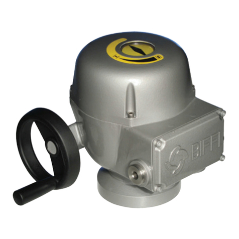
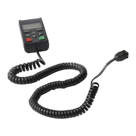
BIFFI ICON3000 Series User manual

Copyright © Biffi. The information in this document is subject to change without notice. Updated data sheets can be obtained from our website www.biffi.it or from your nearest Biffi Center:
Biffi Italia s.r.l. - Strada Biffi 165, 29017 Fiorenzuola d'Arda (PC) – Italy PH: +39 0523 944 411 – [email protected]
Bif ICON3000
Electric Actuator
Service Manual
MDE 252 Rev. 1
December 2021

Revision Details
December 2021
Service Manual
MDE 252 Rev. 1
Revision Details
Revision Details
Rev. Date Description Prepared Approved
1 December 2021 General Update (Migration to new template)
0 May 2018 Initial Release A.B. L.V.

i
Service Manual
MDE 252 Rev. 1
Table of Contents
December 2021
Table of Contents
Table of Contents
Section 1: General Safety Instructions
General Safety Instrctions........................................................................................1
Section 2: Troubleshooting
2.1 Alarms and Warnings ................................................................................... 3
2.2 Alarm Description ......................................................................................... 4
2.2.1 Alarm on Local Display: High Torque in Closing................................... 4
2.2.2 Alarm on Local Display: High Torque in Opening................................. 5
2.2.3 Alarm on Local Display: Jammed Valve in Opening.............................. 6
2.2.4 Alarm on Local Display: Jammed Valve in Closing................................ 7
2.2.5 Alarm on Local Display: Motor Thermostat ......................................... 8
2.2.6 Alarm on Local Display: Internal Temperature..................................... 9
2.2.7 Alarm on Local Display: Position Sensor
(Hardware 11 or Hardware 12) ......................................................... 10
2.2.8 Alarm on Local Display: Speed Sensor............................................... 11
2.2.9 Alarm on Local Display: Mid Travel Alarm in Opening ........................ 12
2.2.10 Alarm on Local Display: Mid Travel Alarm in Closing .......................... 13
2.2.11 Alarm on Local Display: Main Voltage ............................................... 14
2.2.12 Alarm on Local Display: Lost Phase.................................................... 15
2.2.13 Alarm on Local Display: K1 Contactor ............................................... 16
2.2.14 Alarm on Local Display: K2 Contactor ............................................... 17
2.2.15 Alarm on Local Display: Request Signal ............................................. 18
2.2.16 Alarm on Local Display: Low Lithium Battery..................................... 19
2.2.17 Alarm on Local Display: Conguration OBJ n° .................................... 19
2.2.18 Alarm on Local Display: Hardware n°................................................. 20
2.3 Warning Description ................................................................................... 21
2.3.1 Warning on Local Display: High Torque in Closing
(Near to Maximum) .......................................................................... 21
2.3.2 Warning on Local Display: High Torque in Opening
(Near to Maximum) .......................................................................... 21
2.3.3 Warning on Local Display: Internal Temperature
(Near to Maximum) .......................................................................... 21
2.3.4 Warning on Local Display: Main Voltage (Near to Limit).................... 22
2.3.5 Warning on Local Display: Contactor Cycles...................................... 22
2.3.6 Warning on Local Display: Maintenance Request .............................. 22
2.3.7 Warning on Local Display: Wrong Stroke Limit.................................. 22
2.3.8 Warning on Local Display: BUS.......................................................... 22
2.4 The Electronics Does Not Switch on When Powered.................................... 23

ii
Table of Contents
December 2021
Service Manual
MDE 252 Rev. 1
Table of Contents
2.5 DC Output Voltage Not Available at the Actuator Terminals ........................ 23
2.6 The Actuator Does Not Work with Remote Controls.................................... 24
2.7 The Motor is Very Hot and Does Not Start ................................................... 24
2.8 The Motor Runs but the Actuator Does Not Move the Valve ........................ 25
2.9 The Manual Override Cannot Be Engaged.................................................... 26
2.10 The Valve Does Not Seat Correctly .............................................................. 27
2.11 Excessive Torque for Valve Operation .......................................................... 27
2.12 The Actuator Does Not Stop in Fully Open or Fully Closed Position............... 27
2.13 The Numeric Position Display Indicates "---"................................................. 27
2.14 The Electrical Power is off and Numeric Display is Off .................................. 28
2.15 Replacement of the 9 V Lithium Battery ...................................................... 28
2.16 Logic card of ICON3000 .............................................................................. 30
2.17 Instruction to Disconnect C_GRID Connectors............................................ 32

Service Manual
MDE 252 Rev. 1 December 2021
General Safety Instructions 1
Section 1: Introduction
Section 1: General Safety Instructions
This troubleshooting guide is applicable to ICON3000 Multi-turn Electric Actuators, which
are designed to operate any kind of industrial valves for use in heavy industrial, chemical,
petrochemical, food, water, and power generating plants.
Bif will not be liable for any possible damage or physical injury resulting from use in
other than the designated application or by lack of care during installation, operation,
adjustment and maintenance of the machinery. Such risks lie entirely with the user.
Depending on the specic working conditions, additional precautions may be required.
NOTICE
This Manual gives basic information regarding troubleshooting of ICON3000; detailed
information for setting and control of the Electric Actuator part ICON3000 are included on
the VCIOM-08500.
! WARNING
It is assumed that the installation, the setting, the commissioning and the
maintenance and repair works are carried out by qualied personnel and checked by
responsible specialists.
! WARNING
The actuator is non-intrusive. The control compartment was sealed in dry and clean
conditions and contains no site serviceable components. Do not open it unless absolutely
necessary. Unauthorized access will invalidate the warranty.
! WARNING
Since the control and terminal board compartments contain a 9 V and 3.6 V
lithium batteries, only open it in safe area. If the actuator is located in a hazardous
area, a "hot work" permit must be obtained unless the actuator can be moved to a
non-hazardous area.
! WARNING
Do not electrically operate the ICON3000 when the electrical enclosures are removed.
Operating the unit or working on the electronics with the electrical enclosures removed
could cause personal injury.
! WARNING
The actuator is non-intrusive. The control compartments were sealed in dry and clean
conditions and contain no site serviceable components. Do not open it unless absolutely
necessary. Unauthorized access will invalidate the warranty.

December 2021
Service Manual
MDE 252 Rev. 1
Troubleshooting
2
Section 2: Troubleshooting
Section 2: Troubleshooting
The ICON3000 actuator has passed the functional test performed by Bif Quality
Assurance personnel. If the actuator does not work before troubleshooting, make
sure that:
1. The main supply voltage is the same as stated in the nameplate menu.
2. The numeric display indicates the position of actuator in percentage xx %.
3. The local selector is in LOCAL or REMOTE.
4. Move the local selector to OFF and check that the alphanumeric display shows one
of the following messages:
— "NORMAL OFF"
— "ALARM OFF"
— "WARNING OFF"
— "ESD ON OFF"
— "INT OFF"
If the status is ESD ON or INT, an ESD or Interlock command is present. Check the
electrical signals on ESD and Interlock terminals and check the ESD and Interlock
settings (see Installation, Operation and Maintenance Manual, VCIOM-08500 and
electrical diagram).
If the status is ALARM or WARNING use local display to view the type of alarm or warning.
Status Operation
or Position
request R%
Local selector
position
Figure 1
Figure 2
OPEN/YES
STOP
CLOSE/NO

Service Manual
MDE 252 Rev. 1 December 2021
Troubleshooting 3
Section 2: Troubleshooting
2.1 Alarms and Warnings
Warning is the condition that occurs when a variable reaches a critical value and/or when a
maintenance action is required but all actuator functions are still available. The ashing of
the alarm/warning LED indicates a warning condition.
Alarm is the condition that occurs when a variable is outside the acceptable range and
some actuator function is not available. If the alarm/warning LED is on and xed there is an
alarm condition. When the fault condition disappears, the corresponding alarm or warning
also disappears from the list.
A reset routine is provided in the local menu to clear the types of alarms and warnings
that are memorised (over-torque, jammed valve, etc.) (see Installation, Operation and
Maintenance Manual, VCIOM-08500).
View procedure:
1. Move the 3-position selector to either OFF or REMOTE, then press NO to scroll the
list of available variables.
2. Press YES when the display shows message "ALARMS view?" Press YES to scroll the
list of alarms.
3. Press NO when the display shows message "ALARMS view?"
4. Press YES when the display shows message "WARNINGS view?" Press YES to scroll
the list of warnings.
5. Press YES to reset the alarms or warnings with memory.
Figure 3 shows the procedure to view the alarms or warnings detected by the electronics.
XXXXXX XXXXXX
XXXXXX NEXT?
ALARMS VIEW?
ALARM H 1
NEXT?
ALARM H N
NEXT?
RESET OK? RESET OK?
WARNING H N
NEXT?
WARNING H 1
NEXT?
WARNINGS
VIEW?
Display
3-position
selector
LOCAL REMOTE
YES
YES YES
YES
YES
YES
YES
YES
YES
YES
NO
NO
NO
NO
NO
NO
NO
NO
OFF
VIEW
VARIABLES
Figure 3

December 2021
Service Manual
MDE 252 Rev. 1
Troubleshooting
4
Section 2: Troubleshooting
2.2 Alarm Description
2.2.1 Alarm on Local Display: High Torque in Closing
HIGH TORQUE IN CLOSING
Engage the handwheel and verify if the handwheel is completely
blocked in the closing direction.
For extraordinary repairing activity, please contact Bif.
1. The measured torque is greater than the relevant value congured in torque set-up or stroke limits routine.
2. The actuator can operate in opening direction. An electrical command in open direction clears the alarm.
3. Check the valve and the torque needed to move the valve.
4. Check the torque limits in actuator setup, stroke limits and torque setup.
5. Increase the torque limit only if valve stem can accept more torque/thrust/without any damage.
6. Verify if the closing command performs well.
1. Switch off the actuator.
2. Remove the actuator from the valve
by leaving the coupling thrust block
xed onto the valve.
3. Turn the selector in local.
4. Switch on the actuator.
5. Push close button in order to verify
if the actuator moves without
the valve.
6. If the actuator moves well,
please check carefully the
valve or the valve/actuator
mechanical connection.
Please verify (in sequence):
1. Speed sensor (see VCIOM-08500)
2. Cable from speed sensor to
logic board
3. Logic board (if brand new board is
installed, please make sure that the
proper conguration is relevant to
the S/N)
4. Power card
5. Mechanical transmission between
the electric motor and the drive
train (see VCIOM-08500)
Alarm Disappear?
YES
YES
NO
NO
The suggested actions
have solved the problem

Service Manual
MDE 252 Rev. 1 December 2021
Troubleshooting 5
Section 2: Troubleshooting
2.2.2 Alarm on Local Display: High Torque in Opening
HIGH TORQUE IN OPENING
Engage the handwheel and verify if the handwheel is completely
blocked in the opening direction.
For extraordinary repairing activity, please contact Bif.
1. The measured torque is greater than the relevant value congured in torque set-up or stroke limits routine.
2. The actuator can operate in closing direction. An electrical command in close direction clears the alarm.
3. Check the valve and the torque needed to move the valve.
4. Check the torque limits in actuator setup, stroke limits and torque setup.
5. Increase the torque limit only if valve stem can accept more torque/thrust/without any damage .
6. Verify if the opening command performs well.
1. Switch off the actuator.
2. Remove the actuator from the valve
by leaving the coupling thrust block
xed onto the valve.
3. Turn the selector in local.
4. Switch on the actuator.
5. Push open button in order to verify
if the actuator moves without
the valve.
6. If the actuator moves well,
please check carefully the
valve or the valve/actuator
mechanical connection.
Please verify (in sequence):
1. Speed sensor (see VCIOM-08500)
2. Cable from speed sensor to
logic board
3. Logic board (if brand new board is
installed, please make sure that the
proper conguration is relevant to
the S/N)
4. Power card;
5. Mechanical transmission between
the electric motor and the drive
train (see VCIOM-08500)
Alarm Disappear?
YES
YES
NO
NO
The suggested actions
have solved the problem

December 2021
Service Manual
MDE 252 Rev. 1
Troubleshooting
6
Section 2: Troubleshooting
2.2.3 Alarm on Local Display: Jammed Valve in Opening
JAMMED VALVE IN OPENING
Reset the alarm and repeat the open command.
1. If the actuator position % does not change within a preset value dened in the parameter "valve jammed
time" when an opening command is sent, the "Jammed valve in opening" alarm appears.
2. The actuator can operate in closing direction.
3. An electrical command in close direction clears the alarm.
The fault reason may be reconducted to an
external unconventional operation to the
actuator and the stroke limit position need to
be reset.
Please verify (in sequence):
1. Verify all the functionalities of the
manual operation with the manual
engagement of the handwheel,
the proper operation of the
handwheel and the automatic
disengagement in order to verify
any possible damage in the internal
mechanical parts.
2. Verify the mechanical integrity of
the shaft of the position sensor.
Alarm Disappear?
YES NO

Service Manual
MDE 252 Rev. 1 December 2021
Troubleshooting 7
Section 2: Troubleshooting
2.2.4 Alarm on Local Display: Jammed Valve in Closing
JAMMED VALVE IN CLOSING
Reset the alarm and repeat the close command.
1. If the actuator position % does not change within a preset value dened in the parameter "valve jammed
time" when a closing command is sent, the "Jammed valve in closing" alarm appears.
2. The actuator can operate in opening direction.
3. An electrical command in open direction clears the alarm.
The fault reason may be reconducted to an
external unconventional operation to the
actuator and the stroke limit position need to
be reset.
Please verify (in sequence):
1. Verify all the functionalities of
the manual operation with the
manual engagement of the
handweel, the proper operation of
the handwheel and the automatic
disengagement in order to verify
any possible damage in the internal
mechanical parts.
2. Verify the mechanical integrity of
the shaft of the position sensor.
Alarm Disappear?
YES NO

December 2021
Service Manual
MDE 252 Rev. 1
Troubleshooting
8
Section 2: Troubleshooting
2.2.5 Alarm on Local Display: Motor Thermostat
MOTOR THERMOSTAT ALARM
1. The contact of motor thermostat is open for high temperature in the motor windings. Any electrical
command is cleared.
2. Electrical controls of actuator becomes available when motor temperature decreases and contact of the
thermostat closes.
3. Switch off the actuator
4. Open the electric motor cover and verify with a multimeter if the contact between motor terminals TH1
and TH2 is open or closed.
1. The contact is open and the motor
temperature is low.
a. Replace the electric motor.
2. The contact is open and the motor
temperature is high.
a. Check operation duty of motor.
b. Check motor current
c. Check winding resistance of
each phase of stator.
In the above check are correct, replace the
electric motor.
The contact is closed and the motor is ok.
This means that the alarm is false.
In sequence:
1. Verify the cabling between motor
terminals Th1-Th2 and the power
card on connector CN23.
2. Verify the cabling between the
power card (CN22) and logic card
(CN12).
3. If the cabling are ne, replace the
power and/or logic card.
Contact terminals
TH1/TH2?
OPEN CLOSED

Service Manual
MDE 252 Rev. 1 December 2021
Troubleshooting 9
Section 2: Troubleshooting
2.2.6 Alarm on Local Display: Internal Temperature
INTERNAL TEMPERATURE
1. The temperature inside the actuator enclosure is higher than 90 °C or lower than -40 °C . Any electrical
command is cleared.
2. Electrical control of actuator becomes available when temperature is within the range +90 °C, -40 °C.
Check ambient temperature.
Replace the logic card.
1. The actuator is out of the
application range.
2. Please verify with Bif if specic
actuators are available for the
particular climate conditions.
Is ambient temperature
in the range?
YES NO

December 2021
Service Manual
MDE 252 Rev. 1
Troubleshooting
10
Section 2: Troubleshooting
2.2.7 Alarm on Local Display: Position Sensor
(Hardware 11 or Hardware 12)
POSITION SENSOR
The value of the actuator position is not valid in terms of bit, i.e. is not within the set range of bits.
Recongure the stroke limits.
The fault reason may be reconducted to
an external unconventional operation to
the actuator.
Check in sequence:
1. Verify the cabling between the
position sensor and the logic card
(CN14).
2. Replace the position sensor.
3. Replace the logic card.
4. Verify the mechanical integrity of
the shaft of the position sensor.
If the alarm disappears, recalibrate both
stroke limits.
Alarm disappear?
YES NO

Service Manual
MDE 252 Rev. 1 December 2021
Troubleshooting 11
Section 2: Troubleshooting
2.2.8 Alarm on Local Display: Speed Sensor
SPEED SENSOR
The value of the motor speed is not valid in terms of bit, i.e. is not within the set range of bits.
Switch off and then on the actuator.
1. Operate the actuator in open or
close direction.
2. If the alarm reappears, please
refer to the sequence of check on
the right.
Check in sequence:
1. Verify the cabling between the
speed sensor and the logic card
(CN13).
2. Replace the speed sensor.
3. Replace the electric motor.
4. Replace the logic card.
Alarm disappear?
YES NO

December 2021
Service Manual
MDE 252 Rev. 1
Troubleshooting
12
Section 2: Troubleshooting
2.2.9 Alarm on Local Display: Mid Travel Alarm in Opening
MID TRAVEL ALARM IN OPENING
1. The actuator moves in opening direction but during the travel the operation is suddenly stopped.
2. The actuator can operate in closing direction. An electrical command in close direction clears the alarm.
Check in sequence:
1. Increase the parameter "valve jammed time" in the actuator setup, miscellaneous routine
(refer to VCIOM-08500).
2. Verify that the manual override is disengaged.
3. Verify the mechanical integrity of the shaft of the position sensor.
4. Verify the integrity of all the mechanical parts composing the transmission, from the electric motor to
the worm shaft.
5. Check the valve, it could be blocked by an obstacle that obstructs the opening manoeuvre.

Service Manual
MDE 252 Rev. 1 December 2021
Troubleshooting 13
Section 2: Troubleshooting
2.2.10 Alarm on Local Display: Mid Travel Alarm in Closing
MID TRAVEL ALARM IN CLOSING
1. The actuator moves in closing direction but during the travel the operation is suddenly stopped.
2. The actuator can operate in opening direction. An electrical command in open direction clears the alarm.
Check in sequence:
1. Increase the parameter "valve jammed time" in the actuator setup, miscellaneous routine
(refer to VCIOM-08500).
2. Verify that the manual override is disengaged.
3. Verify the mechanical integrity of the shaft of the position sensor.
4. Verify the integrity of all the mechanical parts composing the transmission, from the electric motor to
the worm shaft.
5. Check the valve, it could be blocked by an obstacle that obstructs the closing manoeuvre.

December 2021
Service Manual
MDE 252 Rev. 1
Troubleshooting
14
Section 2: Troubleshooting
2.2.11 Alarm on Local Display: Main Voltage
MAIN VOLTAGE
Check main voltage power supply and frequency on terminals L1, L2 and L3.
Check motor current and check if cable section is correct.
If main voltage, wires and current are correct, recalibrate the voltage sensor; enter the "restricted menu" with the
service password and set the new value of "voltage span" parameter.
Check/replace in sequence:
1. Cable connection between power and logic board.
2. Replace the power board.
3. Replace the logic board.
The failure is not related
to the actuator.
The failure is not related
to the actuator.
Problem solved.
1. Main Voltage power supply is lower than -20% or higher than +20% of the nominal value reported in the
actuator nameplate and nameplate menu.
2. All the electrical commands are cleared. The alarm disappears when main power supply return in the
correct range.
In range?
Is it correct?
Is the problem
still present?
NO
NO
NO
YES
YES
YES

Service Manual
MDE 252 Rev. 1 December 2021
Troubleshooting 15
Section 2: Troubleshooting
2.2.12 Alarm on Local Display: Lost Phase
LOST PHASE
1. The alarm may appear only with 3-phase main power supply.
2. Generally, it is generated in case of fault or lack of one of the 3 phases that supply the actuator.
3. Any electrical command is cleared.
Check main voltage supply and frequency on terminals L1, L2 and L3.
The failure is not in the actuator.
Verify failure causes external to Bif actuator
and possibly in the plant conditions.
Check in sequence:
1. Verify the actuator electric
parameters on the nameplate or in
the technical data and check that
the external wires sections to the
actuator terminals are correct.
2. Verify internal wiring between
terminal board (internal screws
terminals) and power supply board
(connector M2).
3. Verify intern al wiring between
power board (connector CN24) and
logic board (connector CN11).
4. Replace the power supply board.
5. Replace the logic board.
Is power supply ok?
NO YES

December 2021
Service Manual
MDE 252 Rev. 1
Troubleshooting
16
Section 2: Troubleshooting
2.2.13 Alarm on Local Display: K1 Contactor
K1 CONTACTOR
1. When an open or close command is sent (locally or remotely or via bus), the actuator internal automatic
test routine reports a failure of K1 (section K1 of the reversing contactor).
2. The actuator can move only in the direction that not use the contactor K1 and only in the direction which
use K2 (i.e. if, for example, K1 is associated to the opening manoeuvre, only the closing manoeuvre is
available as all the operation linked to K1 are not available. Same logic applied on K2).
Reset the alarm K1:
1. Send an command opposite to that one which has generated the alarm;
2. Or via actuator menu as described on the VCIOM-08500,
Once the alarm is reset, repeat the same command which has generated the alarm.
The failure is removed and the actuator
works but it is important to understand why
the problem occurred and make all those
operations necessary to avoid the problem
to return.
The main reason for the K1 failure is related
to the reversing contactor.
Action to be carried out in sequence:
1. Verify cabling between the power
and the logic board.
2. Replace the power board.
3. Replace the logic board.
The main reason for the K1 failure is related
to the reversing contactor.
Action to be carried out in sequence:
1. Verify cabling between the power
and the logic board.
2. Replace the power board.
3. Replace the logic board.
Is the electric motor
restart running?
NO
YES
Other manuals for ICON3000 Series
10
Table of contents
Other BIFFI Controllers manuals
BIFFI
BIFFI EHO User manual
BIFFI
BIFFI HLRA User manual
BIFFI
BIFFI FCB Series User manual
BIFFI
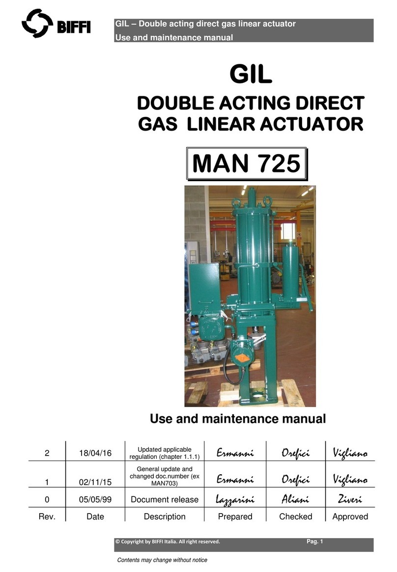
BIFFI GIL MAN 725 User manual

BIFFI
BIFFI ALGA - EAC User manual
BIFFI
BIFFI HLAS-C Series User manual

BIFFI
BIFFI FCB Series Operating instructions
BIFFI
BIFFI TPS Series User manual
BIFFI
BIFFI ALGAS User manual
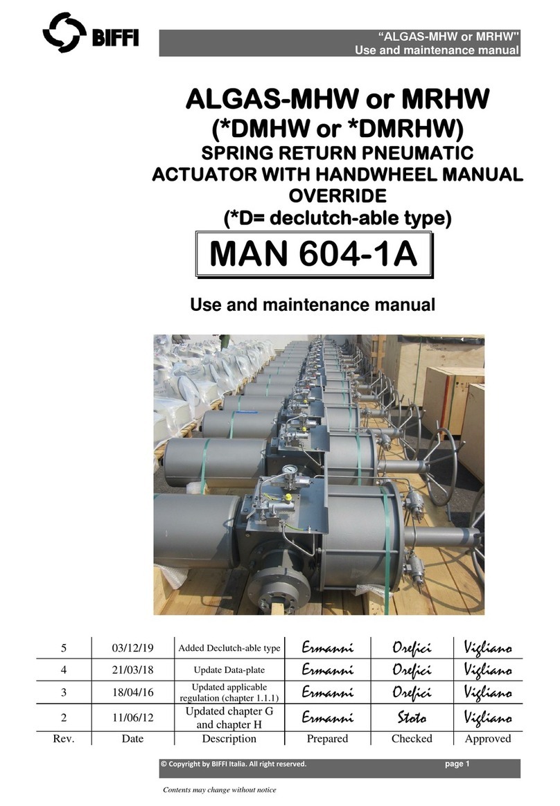
BIFFI
BIFFI ALGAS-MHW User manual
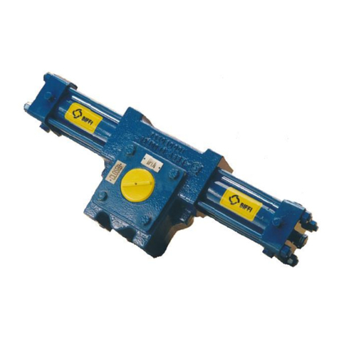
BIFFI
BIFFI RPHD User manual
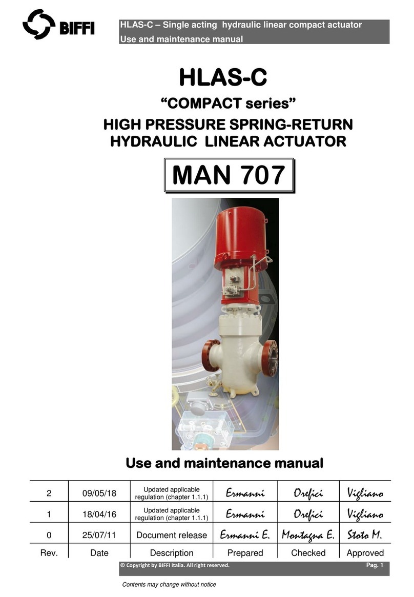
BIFFI
BIFFI COMPACT Series User manual
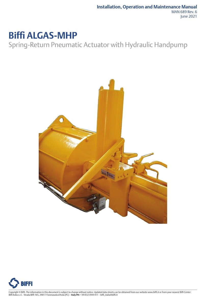
BIFFI
BIFFI ALGAS-MHP User manual
BIFFI
BIFFI OLGA Series User manual
BIFFI
BIFFI ICON3000 Series User manual
BIFFI
BIFFI PLAS Series User manual
BIFFI
BIFFI GILS User manual
BIFFI
BIFFI OLGAS-QA User manual
BIFFI
BIFFI HLAS User manual
BIFFI
BIFFI EFS2000v4 Parts list manual
