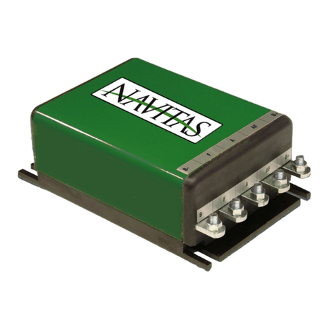
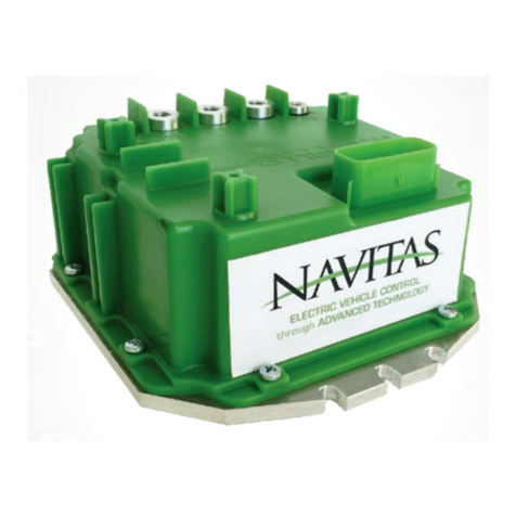
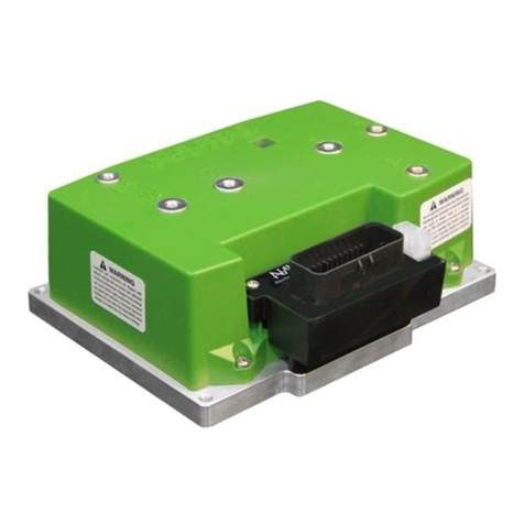
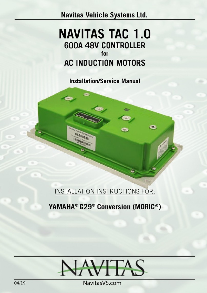
NAVITAS TAC 2 Supplement

Navitas Vehicle Systems Ltd.
INSTALLATION INSTRUCTIONS FOR:
E-Z-GO®RXV® 48V (CURTIS®)
E-Z-GO® RXV® 23 48V (DANAHER®)
E-Z-GO® TXT® 48V Conversion
CLUB CAR® Precedent® Conversion
YAMAHA® YDRE2® TOYOTA®(NEOS®)
YAMAHA
®
G29
®
Conversion (MORIC®)
NAVITAS TAC 2
440A and 600A 48V-72V CONTROLLERS
for
AC INDUCTION MOTORS
Installation/Service Manual
NavitasVS.com
04/19

INSTALLATION/ SERVICE MANUAL
1
Copyright © 2019 Navitas Vehicle Systems Ltd. All Rights Reserved. Patents Pending.
E-Z-GO®, TXT®, and RXV® are registered trademarks of Textron Innovaons, Inc.
(“Textron”). Club Car®, Precedent®, and DS® are registered trademarks of Ingersoll
Rand, Inc., Yamaha®, the tuning fork logo, G-14®, G-19®, G-22®, G-24®, G-29®, and
Drive® are registered trademarks of the Yamaha Golf Car Company (“Yamaha”).
CURTIS is a trademark of Curs Industries, LLC. References to E-Z-GO®, Club Car®,
Yamaha®, or other manufacturers on this manual or any associated electronic or
printed publicaon are solely for purposes of idenfying golf carts.
TABLE OF CONTENTS

INSTALLATION/ SERVICE MANUAL
2
TABLE OF CONTENTS
Contents
Best Practices.............................................................................................3
Introduction TAC 2 (RXV, RXV23, TXT, IQ, YDRE2, G29).................................4
Vehicle Safety Warnings...............................................................................5
Controller Parts List.....................................................................................7
Installation Instructions (Warning/Tools Required)...........................................9
RXV (with Curtis Connection).......................................................................11
RXV23 (with Danaher Connection)...............................................................14
TXT 48 AC Conversion...............................................................................17
Club Car IQ Precedent AC Conversion..........................................................20
YAMAHA YDRE2 - Toyota (with NEOS connection).......................................23
YAMAHA G29 AC Conversion (with MORIC Connection)................................26
Troubleshooting.........................................................................................29
Accessories...............................................................................................34
Appendix A - 4 KW and 5 KW AC Motor Techsheets......................................35
Warranty...................................................................................................39

INSTALLATION/ SERVICE MANUAL
3
Speed Control
• To maximize your vehicle’s driving range only use the speed you need if using the OTF.
• Use the speed knob to control your maximum cruising speed, turn the speed down to the
minimum practical speed necessary for the application. The controller signicantly increases
the operating efciency of the motor as the maximum speed adjustment is reduced.
• Minimize acceleration - hard acceleration demands high in-rush currents from the battery
pack. This increases wear and tear on both the motor and the mechanical systems.
Hill Descent
• Use regenerative braking for hill descent - it puts energy back into the battery and it
increases the life of your brakes. Regenerative Braking can be applied gradually and can
reduce the likelihood of losing traction when going down a hill.
Low Battery Warning
• When the battery discharged warning (1-5 ash) is given by the OTF (if present), the
controller will reduce the amount of power it supplies to the motor to protect the motor.
• Cycling the key will reset full controller power for 1 minute but doing so repeatedly will
adversely affect the life of your motor. Recharge the batteries as soon as possible.
Heavy Duty Usage
• If you notice that your cables or motor are becoming too hot to touch, then your application
is probably too demanding and we recommend that you upgrade the motor to a speed/torque
system, and upgrade the cables to at least 4 AWG.
Warnings
• Always monitor the motor & battery wiring temperatures after changing the programmer
settings (if OTF is present) – particularly when going to higher speeds
• If your battery pack is full, the amount of regenerative braking may be reduced since the
controller has nowhere to put the excess energy.
BEST PRACTICES

INSTALLATION/ SERVICE MANUAL
4
NAVITAS TAC 2 48-72V 440A / 600A Controller
AC INDUCTION MOTOR CONTROLLER
• The owner, and all vehicle operators MUST read and understand all warnings and
instructions in this manual and in the Vehicle Owner/Operator’s Manual. The owner of
this vehicle assumes all liability for accidents, injuries or damages if the warnings and
instructions are not followed.
• Navitas Vehicle Systems Ltd. assumes no responsibility for errors or omissions in this
manual, in regards to liability or damages resulting from the use of information contained in
the manual. If it is lost or damaged please contact your local dealer.
• Navitas Vehicle Systems Ltd. reserves the right to make changes to the controller, parts of
the controller, accessories, labelling or instructions without obligation to make these changes
on units previously sold.
• Product and specications are subject to change without notice or obligation.
ATTENTION:
• BEFORE INSTALLING THIS CONTROLLER PLEASE RECORD THE SERIAL NUMBER LOCATED ON THE
BODY OF THE CONTROLLER.
INTRODUCTION
PART SERIAL #
RXV TAC 2 440A/600A 48-72V
CONTROLLER with BT
10-000878-01/10-000880-01
RXV23 TAC 2 440A/600A 48-72V
CONTROLLER with BT
10-000878-02/10-000880-02
TXT TAC 2 440A/600A 48-72V
CONTROLLER with BT
10-000888-03/10-000890-03
CLUB CAR TAC 2 440A/600A 48-72V
CONTROLLER with BT
10-000888-02/10-000890-02
YAMAHA YDRE2 TAC 2 440A/600A 48-72V
CONTROLLER with BT
10-000888-01/10-000890-01
YAMAHA G29 TAC 2 440A/600A 48-72V
CONTROLLER with BT
10-000888-09/10-000890-09

INSTALLATION/ SERVICE MANUAL
5
• Modifying motor controller parameters may change vehicle acceleration, braking
and top speed behavior. Please verify vehicle performance before the use and obey
federal, county and municipality bylaws and regulations.
• Product use is for golf car and Low Speed Vehicle (LSV) market application and
may operate at speeds Up to 25 MPH. Factory settings on controller have been set
using: 18 inch diameter tires, non-performance motor & up to 25 MPH limit with
vehicle speed sensor installed.
• Operators/Users of Navitas golf car and LSV equipped products must follow
published golf car & LSV federal, state, county & municipal bylaws & regulations
issued for your “use area”. For operation/use beyond golf car & LSV regulations/
guidelines, full liability Is assumed by operators/users.
• Do not leave children or pets unattended in or near the vehicle. Always look behind
you before and while backing up.
• Reduce speed when towing and allow more room for stopping and turning.
• Drive with wheels straight when going up and down hills. Slow down and use
brakes when going down hills.
• Never drive on hills with a slope greater than 15 degrees.
• Do not drive through fast owing water or water above the oor of the vehicle.
• If you must cross shallow water, make sure to stop and inspect the area for sudden
drop-offs, large rocks or slippery surfaces. Always proceed with caution or choose a
safer route.
• When towing this vehicle make sure the key is turned off, the Run/Tow switch is in
Tow, and batteries main power is disconnected.
FAILURE to follow the WARNINGS below can damage
the Vehicle and/or cause SERIOUS INJURY OR DEATH!
DANGER
MAKE SURE TO READ and UNDERSTAND the OWNER’S INSTALLATION and SERVICE MANUAL
and ALL WARNING LABELS with this Controller.
Make sure to also Read, Understand, and follow the Vehicle’s OWNER’S MANUAL and
ALL INSTRUCTIONS and WARNING LABELS.
• Always proceed with caution. Keep speed low and do not drive faster than conditions
permit. Terrain, conditions, and the operator’s skill will determine a safe speed. Avoid
sharp turns and do not accelerate quickly when turning as this can cause the vehicle
to slide sideways or skid out of control. Abrupt manoeuvres or aggressive driving can
cause a rollover even on at open areas.
• This controller will increase torque, but DOES NOT increase the GVWR (Gross Vehicle
Weight Rating), cargo capacity, or towing capacity of the vehicle. Always follow the
vehicle towing and loading specications.
SAFETY WARNINGS

INSTALLATION/ SERVICE MANUAL
6
• Never exceed the towing capacity rating as specied by the vehicle manufacturer.
• Never re-wire, by-pass or change the wires, switches, or controller. Contact your
dealer if vehicle is not operating correctly.
• Keep the controller and the area around it clean and free of debris. Keep electrical
components dry and DO NOT wash with direct stream or power washer
• Driver must be a minimum of 16 years of age with a current driver’s license, or be
accompanied by a parent or legal guardian when operating the car.
• Do not drive vehicles while inuenced by alcohol, medications & drugs as this may/
will impair your safe driving use.
• User to verify that golf car & LSV vehicle mechanical brakes are fully functional
prior to continued operation of vehicle.
• Vehicle & all parts must be serviced by qualied service personnel. For an
authorized service location see your local dealer or visit our web site at www.
NavitasVS.com.
SAFETY WARNINGS, cont’d

INSTALLATION/ SERVICE MANUAL
7
Conrm that all parts listed below are with your kit before starting installation.
If you are missing parts please contact your local dealer.
AC Induction Kit-Curtis 1206AC E-Z-GO RXV 10-000879-01 (440A) / 10-000881-01 (600A)
PART DESCRIPTION PART NUMBER QTY
TAC 2 Controller 440A 10-000878-01 1
TAC 2 Controller 600A 10-000881-01 1
TAC 2 Module 40-000620 1
Cable for-RXV 40-000583 1
AC CONTROLLER PARTS LIST
AC Induction Kit-Danaher E-Z-GO RXV23 10-000879-02 (440A) / 10-000881-02 (600A)
PART DESCRIPTION PART NUMBER QTY
TAC 2 Controller 440A 10-000878-02 1
TAC 2 Controller 600A 10-000881-02 1
TAC 2 Module 40-000623 1
TAC RXV23 Mounting Plate Kit 20-001844 1
Hardware Mounting Kit 10-000843 1
Wiring for RXV23 resistor 40-000582 1
TAC-IQ PRECEDENT 10-000889-02 (440A) / 10-000891-02 (600A)
PART DESCRIPTION PART NUMBER QTY
TAC 2 Controller 440A 10-000888-02 1
TAC 2 Controller 600A 10-000891-02 1
TAC 2 Module 40-000621 1
TAC IQ Mounting Plate Kit 20-001843 1
Hardware Mounting Kit 10-000845 1
AC Motor 4KW (440A) / 5kW (600A) 10-000815 / 10-000823 1
AC Motor Phase Cable 40-000584 1
Cable for TAC-TXT/IQ - Speed Sensor / Motor Temperature 40-000580 1
EZ-GO TXT 10-000889-03 (440A) / 10-000891-03 (600A)
PART DESCRIPTION PART NUMBER QTY
TAC 2 Controller 440A 10-000888-03 1
TAC 2 Controller 600A 10-000891-03 1
TAC 2 Module 40-000622 1
TAC TXT Mounting Plate Kit 20-001843 1
Hardware Mounting Kit 10-000834 1
AC Motor 4KW (440A) / 5kW (600A) 10-000816 / 10-000822 1
AC Motor Phase Cable 40-000584 1
Cable for TAC-TXT/IQ - Speed Sensor / Motor Temperature 40-000580 1
Run/Tow Switch Mounting Plate 20-001603 1

INSTALLATION/ SERVICE MANUAL
8
AC Induction Kit–YAMAHA YDRE2–TOYOTA (NEOS) 10-000889-01 (440A) / 10-000891-01 (600A)
PART DESCRIPTION PART NUMBER QTY
TAC 2 Controller 440A 10-000888-01 1
TAC 2 Controller 600A 10-000891-01 1
TAC 2 Module 40-000627 1
Mounting Plate Kit 20-001843 1
Battery Cable 40-000583 1
Hardware Mounting Kit 10-000833 1
TAC 2 - YAMAHA G29 10-000889-09 (440A) / 10-000891-09 (600A)
PART DESCRIPTION PART NUMBER QTY
TAC 2 Controller 440A 10-000888-09 1
TAC 2 Controller 600A 10-000891-09 1
TAC 2 Module 40-000632 1
Mounting Plate 20-001843 1
AC Motor Phase Cable 40-000584 1
Motor Sensor Cable 40-000580 1
4 KW AC Motor 10-000816 1
Ring Terminal for A2 Cable 40-000536 1
Hardware Mounting Kit 10-000833 1
AC CONTROLLER PARTS LIST cont’d

INSTALLATION/ SERVICE MANUAL
9
INSTALLATION INSTRUCTIONS
ATTENTION:
• Before installing the controller make sure that the golf car’s electrical
system is working properly.
• All components such as the motor, Run/Tow switch, pedal cluster, FWD/
REV switch and all wiring needs to be in good condition and operating to
manufacturer’s standards.
• The batteries must be in good condition and each battery must hold a
charge!
• If the system is not working properly this must be repaired before
installing this controller!
FAILURE to follow the WARNINGS below can damage
the Vehicle and/or cause SERIOUS INJURY OR DEATH!
DANGER
Installation or Servicing of the NAVITAS 440A / 600A 48-72V Controller must be done by a
trained golf car technician. Before installing or servicing of the NAVITAS Controller:
• Disconnect the main (+) positive and (-) negative cable on the vehicle’s battery system.
• Make sure the Run/Tow switch is in the Tow position
• The Key is turned OFF and removed from the ignition
• The parking brake is engaged
• Before testing the controller/vehicle make sure ALL four wheels are off the ground
and supported with jack stands.
• The area around the vehicle must be clear. Keep all people, children and pets away
from the vehicle when installing, servicing or testing the vehicle.
• Read NAVITAS 440A / 600A 48-72V Controller Installation/Service and all warning
labels before servicing or troubleshooting this Vehicle.
• The controller is sealed and cannot be opened for service. To replace the controller
call your local dealer. Opening the controller will void the warranty
• Wear safety glasses and gloves when installing this controller.
• Wear a safety shield when working in or near the vehicle battery compartment.
• Use insulated tools to protect from electric burns.
• Never lay or put down tools in the vehicle battery compartment.
• Remove pre-charge resistor from contactor and discard.

INSTALLATION/ SERVICE MANUAL
10
INSTALLATION INSTRUCTIONS
REQUIRED TOOLS
• #3 Phillips screwdriver
• 10, 11, & 13mm wrench
• Socket driver w/ extension
• Wire cutters
• Assorted socket set
• Safety glasses
• Flashlight (optional)
REQUIRED TOOLS & PARTS
Disconnect all batteries before beginning
installation. If the car has a Run/Tow switch, you
must place the switch in the TOW position rst!
CAUTION
PURCHASED PARTS
• Controller w/ Bluetooth
• Mounting Plate w/ hardware
• On-The-Fly Programmer
ALL 6 mm Bolt 60 in-lbs/ 5 ft-lbs/ 6.8 Nm
Battery 5/16 Thread 90 in-lbs

INSTALLATION/ SERVICE MANUAL
11
INSTALLATION INSTRUCTIONS
1. Power down
• Turn off key, disconnect battery
• Put car on a stand and block wheels
• Use insulated tools
• Never use battery as workbench
2. Remove OEM Controller
• Remove OEM protective cover
• Remove the battery positive bus bar
• Remove resistor wires
• Remove battery negative cable
• Remove resistor cage with solenoid
• Unplug Harness
• Remove motor phase cables.
• Unbolt and remove the controller
3. Install Navitas TAC 2 Controller
• Route motor cables to new controller
around outside of controller mount
• Remove bolts, washer, lock washer from
top of new controller.
• Fasten TAC 2 Controller to existing
mounting bracket using original hardware
(Fig. 2)
PARTS
• AC controller
• B+ cable (for solenoid to controller)
• On-The-Fly programmer
Disconnect all batteries before beginning installation.
If the car has a Run/Tow switch, you must place the
switch in the TOW position rst!
CAUTION
RXV Installation
To view our Installation
video for Golf Cars, visit:
NavitasVS.com/support
Fig. 1
Fig. 2

INSTALLATION/ SERVICE MANUAL
12
INSTALLATION INSTRUCTIONS
4. Connect Navitas TAC 2 Controller (Fig. 3)
• Connect cables using bolts, washers and
lock washers: U to U, V to V, W to W
• Fasten NEW battery positive cable (B+ from
controller to solenoid)
• Re-fasten resistor cage with solenoid
mounted on it.
• Add battery positive cable to solenoid
and add black lead from resistor on top of
battery cable and tighten w/13mm wrench
or socket
• Tighten back positive terminal
• Add wire from the resistor to the “resistor
output” of the controller and tighten
w/10mm wrench or socket
• Connect battery negative cable - Tighten w/10mm wrench or socket.
5. Connect RXV OEM harness (Fig. 3)
• Insert RXV OEM harness into adapter module
• The Programming end of the CURTIS harness will NOT be used
• Re-connect the cover.
6. Install On the Fly Programmer (Optional)
• Unclip the three nuts to remove cup holders
• Feed end of cable through body hole on the dash and leave enough slack to mount the OTF on
the dash
• Mount on On-the-Fly programmer on the dash w/ Velcro strap
• Feed cable back through the channel to the oor and chase back following wiring harness to
the Navitas adaptor module and connect it. Zip tie cable to the factory wiring harness
• Connect OTF programming end into the adaptor module, and connect original controller
harness into adaptor module;
• Zip tie motor phase wires to resistor cage
• Original communication plug from OEM controller not used
• Re-Connect cover
• Mount OTF on the dash
• Re-power the system by Connecting battery connection.
7. Test installation
• Lift drive wheels off ground
• Reconnect battery pack
• Switch to Run mode
• Turn key to Forward
• Press on throttle to activate wheels.
RXV Installation cont’d
Fig. 3

INSTALLATION/ SERVICE MANUAL
13
INSTALLATION INSTRUCTIONS
RXV Installation cont’d
Pinout for Controller
Diagrams and other updates available at:
NavitasVS.com/support
To OEM vehicle harness
P1: Key In
P2: Reverse Buzzer
P3: NA
P4: Brake Light Relay Release
P5: Brake Solenoid Out
P6: Main Solenoid Out
P7: Logic Power GND
P8: Motor Temperature In
P9: Foot Switch In
P10:Tow Switch In
P11:Charger Interlock In
P12:Brake Switch In
P13: NA
P14: NA
P15:+5V PF
P16:Throttle In
P17:Brake In
P18:Anolog GND
To OTF Programmer
PN: 10-000686
P1: +12V PF
P2: OTF Regen
P3: OTF speed
P4: OTF acceleration
P5: +5V PF
P6: OTF Lock
P7: OTF LED
P8: Analog Ground
Navitas TAC2 AC Motor Controller
for EZ-GO RXV
Product Model 10-000878-01
35-POS Ampseal
1-776231-1
8-POS Molex
39-28-1083 P19:NA
P20:NA
P21:NA
P22:Forward In
P23:CAN Positive
P24:NA
P25:+12V Output
P26:+5V PF
P27:NA
P28:NA
P29:NA
P30:SOC Display Out
P31:SPD A In
P32:SPD B In
P33:Reverse In
P34:Analog Ground
P35:CAN Negative
35
1
Module 40-000620
TAC2 for RXV
OTF
Issue Date: 20181219
Navitas TAC2 AC Motor Controller
for RXV
Product Model 10-000880-01 (440A)
10-000880-01 (600A)

INSTALLATION/ SERVICE MANUAL
14
1. Power down
• Turn off key, disconnect battery
• Put car on a stand and block wheels
• Use insulated tools
• Never use battery as workbench
2. Remove OEM Controller
• Remove OEM Protective cover
• Remove solenoid (Fig. 1) - keep wires connected
• Remove resistor cage
• Remove motor phase cables and resistor cable,
B- cable from controller
• Unclip Harness wires
• Remove plate (along with Danaher controller
and black resistor module and wires)
3. Install New Mounting Plate (Fig. 2)
• Install plate in existing location using OEM
hardware.
INSTALLATION INSTRUCTIONS
RXV 23 (Danaher) Installation
Disconnect all batteries before beginning installation.
If the car has a run/tow switch, you must place the
switch in the TOW position rst!
CAUTION
Parts:
• AC Navitas controller with Bluetooth
• On-The-Fly programmer (optional)
• Mounting plate and hardware
• Resistor wire (longer for replacement)
To view our Installation
video for Golf Cars, visit:
NavitasVS.com/support
Fig. 1
Fig. 2

INSTALLATION/ SERVICE MANUAL
15
4. Mount Controller (Fig. 3)
• Use supplied bolts / washers / lock washers
• Bolt plate from back side
• Connect harness at bottom
5. Connect Controller
• Replace existing resistor cable (with NEW
included longer resistor cable) to resistor output
on controller
• Re-fasten resistor cage to the plate
• Re-fasten solenoid to the cage using 2 of the OEM
bolts (Fig. 4)
• Connect battery B- cable from battery pack to
controller
• Connect motor phase cables (U,V,W)
• Connect battery to B+ from solenoid
6. Connect OEM Wire Harness (Fig. 5 & 6)
• Connect OEM wire harness to adaptor module
7. Install On-The-Fly Programmer (optional)
• Install OTF (optional) (see install description in
RXV INSTALL instructions, p12)
• Connect OTF to Navitas adaptor module
• Zip Tie loose cables
8. TESTING INSTALLATION
• Lift drive wheels off ground
• Reconnect battery pack
• Turn Key to Forward Position
• Press on Throttle to activate wheels
INSTALLATION INSTRUCTIONS
RXV 23 (Danaher) Installation cont’d
Fig. 6
Fig. 5
Fig. 4
Fig. 3

INSTALLATION/ SERVICE MANUAL
16
INSTALLATION INSTRUCTIONS
RXV 23 (Danaher) Installation cont’d
Pinout for Controller
Diagrams and other updates available at:
NavitasVS.com/support
P1: Key In
P2: Brake Solenoid Out
P3: +5V PF
P4: AGND
P5: SPD A In
P6: SPD B In
P7: Brake In
P8: NA
P9: Throttle In
P10:Reverse Buzzer Out
P11:SOC Display Out
P12:Forward In
P13:Tow Switch In
P14:NA
P15:NA
P16:Motor Temperature In
P17:Charger Interlock In
P18:MAIN Solenoid Out
P19:Foot Switch In
P20:Reverse In
P21:NA
P22:Brake Light Relay Release
P23:NA
To OEM vehicle harness
To OTF Programmer
PN: 10-000686
P1: +12V PF
P2: OTF Regen
P3: OTF speed
P4: OTF acceleration
P5: +5V PF
P6:OTF Lock
P7: OTF LED
P8: Analog Ground
Navitas TAC2 AC Motor Controller
for EZ-GO RXV Danaher
Product Model 10-000878-02
8-POS Molex
39-28-1083
23-POS Ampseal
776228-1
23
1
Module 40-000623
TAC2 for RXV Danaher
OTF
Issue Date: 20181219
Navitas TAC2 AC Motor Controller
for EZ-GO RXV Danahar
Product Model 10-000880-01 (440A)
10-000880-02 (600A)

INSTALLATION/ SERVICE MANUAL
17
1. Power down
• Turn off key, disconnect battery
• Put car on a stand and block wheels
• Use insulated tools
• Never use battery as workbench
2. Remove OEM Protective Cover
• Remove cables from controller
• Unclip OEM Wire Harness
3. Remove OEM Controller
4. Install TXT Mounting Plate
• Align plate with existing holes (where OEM controller
was fastened) and fasten with screws (Fig. 2)
INSTALLATION INSTRUCTIONS
E-Z-GO DC to AC Conversion
Disconnect all batteries before beginning installation.
If the car has a run/tow switch, you must place the
switch in the TOW position rst!
CAUTION
PARTS INCLUDED
• AC Controller
• AC 4 kW motor
• On-The-Fly programmer
(Optional)
• Mounting plate and
hardware
• Run/Tow switch mount
• Motor phase cable
• Speed sensor/motor
temperature harness
To view our Installation
video for Golf Cars, visit:
NavitasVS.com/support
Fig. 1
Fig. 2

INSTALLATION/ SERVICE MANUAL
18
5. Mount Controller
• Install Navitas AC controller (Fig. 3)
• Attach Run/Tow switch mount and fasten Run/Tow
switch to mount.
• Connect B- from battery, B+ from solenoid and
motor phase cables to U, V, W (use new cable
provided as ‘W’ and re-use the 2 existing motor
phase cables from A1=U, A2=V) to the controller
(Fig. 5)
6. Motor Conversion
• Remove motor phase cables A1, A2 from motor
• Remove and DISCARD eld cables (F1, F2)
• Remove DC motor
• Install Navitas AC motor
• Connect new speed sensor/motor temp harness to
motor (Fig. 4)
• Connect motor phase wires from controller (A1 =U,
A2 = V and new cable = W) (Fig. 6)
• Check cabling to make sure U, V, and W match
exactly from motor to controller (Fig. 6)
7. Connect OEM Harness to Adaptor Module
8. Connect Speed Sensor/Motor Temperature Wire
Harness to Controller (Fig. 5)
9. Install On-The-Fly Programmer (optional)
• Install OTF (optional) (see install description in RXV
INSTALL instructions, p12)
• Connect OTF to Navitas Controller
• Zip Tie loose cables
10. Test Installation
• Lift rear wheels
• Reconnect battery pack
• Put in “RUN” mode
• Turn key on
• Put in “F” for Forward
• Press on throttle to activate wheels
INSTALLATION INSTRUCTIONS
E-Z-GO DC to AC Conversion cont’d
Fig. 3
Fig. 4
Fig. 5
Fig. 6

INSTALLATION/ SERVICE MANUAL
19
INSTALLATION INSTRUCTIONS
Pinout for Controller
E-Z-GO DC to AC Conversion cont’d
Diagrams and other updates available at:
NavitasVS.com/support
P1: ITS Throttle Negative
P2: ITS Throttle Positive
P3: Fused GND
P4: NA
P5: Charger Interlock Input
P6: Foot Switch In
P7: Reverse Buzzer
P8: Forward In
P9: Logic Power In
P10:Key In
P11: NA
P12:Main Solenoid Out
P13: NA
P14: NA
P15: NA
P16:Reverse In
To Navitas AC Motor Adapter
PN: 40-000580
P1: +5V PF
P2: Encoder A In
P3: Encoder B In
P4: Digital GND
P5: NA
P6: Motor Temperature In
P7: Analog GND
P8: NA
P9: Key In
P10: Motor Brake Solenoid Release
To OEM vehicle harness
(Curtis 1206HB)
To OTF Programmer
PN: 10-000686
P1: +12V PF
P2: OTF Regen
P3: OTF speed
P4: OTF acceleration
P5: +5V PF
P6: OTF Lock
P7: OTF LED
P8: Analog GND
Navitas TAC2 AC Motor Controller
for EZ-GO TXT DC-AC Conversion
Product Model 10-000888-03
8-POS Molex
39-28-1083
16-POS Molex
39-28-1163
10-POS Molex
39-28-1103
Navitas AC Motor Adapter
40-000580 To AC Motor
Speed Sensor
Temperature Sensor
2-POS
282080-1
4-POS
282088-1
10-POS Molex
39-01-2100 P1: Motor Temperature In
P2: Analog GND
P1: +5V PF
P2: Encoder B In
P3: Encoder A In
P4: Digital GND
P1: +5V PF
P2: Encoder A In
P3: Encoder B In
P4: Digital GND
P5: NA
P6: Motor Temperature In
P7: Analog GND
P8: NA
P9: NA
P10: NA
Module 40-000622
TAC2 for TXT
OTF
AC Motor
Adapter
Vehicle Harness
Issue Date: 20181219
RES Post may not be installed in conversion model!
Navitas TAC2 AC Motor Controller
for EZ-GO TXT DC-AC Conversion
Product Model 10-000888-03 (440A)
10-000880-03 (600A)
Other manuals for TAC 2
1
Table of contents
Other NAVITAS Controllers manuals
Popular Controllers manuals by other brands

CD Automation
CD Automation REVEX 2PH 120A user manual

SIIG
SIIG Smart Controller for HDMI over IP Series user manual

Siemens
Siemens LMO64 Series manual

FASAR ELETTRONICA
FASAR ELETTRONICA FE230 quick start guide

Mitsubishi Electric
Mitsubishi Electric FX Series Training manual

RKC INSTRUMENT
RKC INSTRUMENT THV-1 instruction manual