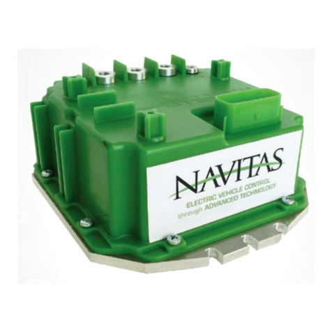
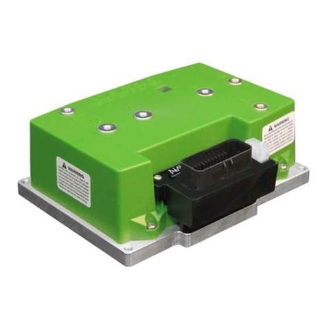
NAVITAS TAC 1.0 Supplement

Navitas Vehicle Systems Ltd.
INSTALLATION INSTRUCTIONS FOR:
YAMAHA
®
G29
®
Conversion (MORIC®)
NAVITAS TAC 1.0
600A 48V CONTROLLER
for
AC INDUCTION MOTORS
Installation/Service Manual
NavitasVS.com
04/19

INSTALLATION/ SERVICE MANUAL
2
INSTALLATION INSTRUCTIONS
ATTENTION:
• Before installing the controller make sure that the golf car’s electrical
system is working properly.
• All components such as the motor, Run/Tow switch, pedal cluster, FWD/
REV switch and all wiring needs to be in good condition and operating to
manufacturer’s standards.
• The batteries must be in good condition and each battery must hold a
charge!
• If the system is not working properly this must be repaired before
installing this controller!
FAILURE to follow the WARNINGS below can damage
the Vehicle and/or cause SERIOUS INJURY OR DEATH!
DANGER
Installation or Servicing of the NAVITAS 440A / 600A 48-72V Controller must be done by a
trained golf car technician. Before installing or servicing of the NAVITAS Controller:
• Disconnect the main (+) positive and (-) negative cable on the vehicle’s battery system.
• Make sure the Run/Tow switch is in the Tow position
• The Key is turned OFF and removed from the ignition
• The parking brake is engaged
• Before testing the controller/vehicle make sure ALL four wheels are off the ground
and supported with jack stands.
• The area around the vehicle must be clear. Keep all people, children and pets away
from the vehicle when installing, servicing or testing the vehicle.
• Read NAVITAS 440A / 600A 48-72V Controller Installation/Service and all warning
labels before servicing or troubleshooting this Vehicle.
• The controller is sealed and cannot be opened for service. To replace the controller
call your local dealer. Opening the controller will void the warranty
• Wear safety glasses and gloves when installing this controller.
• Wear a safety shield when working in or near the vehicle battery compartment.
• Use insulated tools to protect from electric burns.
• Never lay or put down tools in the vehicle battery compartment.
• Remove pre-charge resistor from contactor and discard.

INSTALLATION/ SERVICE MANUAL
3
INSTALLATION INSTRUCTIONS
YAMAHA G29 DC to AC Conversion
Disconnect all batteries before beginning installation.
If the car has a run/tow switch, you must place the
switch in the TOW position rst!
CAUTION
1. Power down
• Turn off key, disconnect battery
• Put car on a stand and block wheels
• Use insulated tools
• Never use battery as workbench
2. Remove OEM Controller / Solenoid & Mounting Plate
• Remove cables from controller
• Unclip OEM Wire Harness
3. Prepare Cables
• Locate the ‘Y’ cable on the vehicle harness (Fig. 1). This
cable consists of 2 cables crimped together into a sigle
ring terminal. One side comes from the Battery Negative.
The other wire is connected to the A2 on the motor. Use side cutters to cut the A2 wire
at the ring terminal (Fig. 2). Then crimp the supplied ring terminal to the A2 wire (Fig. 3).
PARTS INCLUDED
• AC Controller
• Adaptor harness
• AC 4 kW motor
• OTF programmer (optional)
• Mounting plate and
hardware
• Motor phase cable
• Speed sensor/motor
temperature harness
• Ring Terminal
To view our Installation
video for Golf Cars, visit:
NavitasVS.com/support
Fig. 2 Fig. 3 Fig. 4
Fig. 1

INSTALLATION/ SERVICE MANUAL
4
INSTALLATION INSTRUCTIONS
YAMAHA G29 DC to AC Conversion cont’d
4. Install G29 Mounting Plate
• Align plate with existing holes (where OEM controller
was fastened) and fasten with screws (Fig. 5)
5. Mount Controller
• Install Navitas AC controller (Fig. 6).
• Re-install solenoid to plate
• Connect B- from battery, B+ from solenoid and motor
phase cables to U, V, W (use new cable provided as
‘W’ and re-use the 2 existing motor phase cables
from A1=U, A2=V) to the controller (Fig. 6)
6. Motor Conversion
• Remove motor phase cables A1, A2 from motor
• Remove and DISCARD eld cables (F1, F2)
• Remove DC motor
• Install Navitas AC motor
• Connect new speed sensor/motor temp harness to
motor
• Connect motor phase wires from controller (A1 =U,
A2 = V and new cable = W)
• Check cabling to make sure U, V, and W match exactly from motor to controller
7. Connect OEM Harness to Adaptor Harness
8. Install On-The-Fly Programmer (optional)
• Install OTF (optional) (see install description in RXV INSTALL instructions, p12)
• Connect OTF to the adapter module
• Zip Tie loose cables
9. Test Installation
• Lift rear wheels
• Reconnect battery pack
• Put in “RUN” mode
• Turn key on
• Put in “F” for Forward
• Press on throttle to activate wheels
Fig. 5
Fig. 6

INSTALLATION/ SERVICE MANUAL
5
Pinout for Controller
INSTALLATION INSTRUCTIONS
YAMAHA G29 DC to AC Conversion cont’d
Diagrams and other updates available at:
NavitasVS.com/support
To OEM vehicle harness
Yamaha G29
TAC1.0 harness for Yamaha G29
Navitas Part Number: 40-000630
P1: NA
P2: Charger Interlock Signal
P3: (CP20) Line Contactor
P4: (CP19) Rev Buzzer
P5: (CP11) +5V
P6: (CP18) GND Poly
P7: (CP15) Throttle In
P8: (CP8) Key
P9: (CP6) Rev In
P10: (CP7) Fwd In
P11: (CP17) Foot Switch
P12: (CP10) Logic Power
P13: (CP10) Logic Power
P14: (CP4) Speed Sensor
P15: (CP11) +5V
P16: (CP18)GND Poly
P17: NA
P18: NA
P19: NA
P20: NA
P21: NA
P22: NA
P23: NA
P24: (CP18) GND Poly
P25: (CP11) +5V
P26: (CP4) Speed Sensor
Navitas PN: 10-000686
OnTheFly Programmer
P1: +12V PF
P2: OTF Regen
P3: OTF speed
P4: OTF acceleration
P5: +5V PF
P6: OTF Lock
P7: REV BUZ
P8: AGND
26 POS Molex
MX23A26NF1
CP=Controller Pinout
40-POS Molded
TSX Connector
1
1 Digital Ground
2 +5V Output
3 Fused Ground
4 OnTheFly Programmer Regen Brake
5 Throttle Input
6 Analog Brake Input
7 Analog Ground
8 Reverse Switch Input
9 Digital Ground
10 Throttle Start Switch (Foot Switch)
11 OnTheFly Programmer Lock
12 Encoder Input C
13 Factory Programming
14 Serial RX Line
15 Serial TX Line
16 Digital Ground
17 Key Switch Input
18 Charger Interlock Input
19 Tow Switch Input
20 CAN +
21 Digital Ground
22 Logic Power
23 Analog Ground
24 Analog Ground
25OnTheFly Programmer Acceleration
26 OnTheFly Programmer Speed
27 Motor Temperature Input
28 SOC Display Output
29 Analog Ground
30 +12V Output
31 Brake Switch
32 Encoder Input B
33 Encoder Input A
34 Forward Switch Input
35 Digital Ground
36 Reverse Buzzer Ouput
37 Motor Brake Solenoid Release
38 Main Solenoid Output
39 Brake Light
40 CAN-
20
21
40
1
1
W
B+
V
B-
U
Motor W
Motor U
Battery Neg
Motor V
RES
Brake Resistor
Navitas TAC AC Motor Controller
Controller Pinout (CP)
10-POS Molex
39-28-1103
Connect to Navitas
PN: 40-000580
AC Motor Adapter
P1: (CP2) +5V PF
P2: (CP33) Encoder Input A
P3: (CP32) Encoder Input B
P4: DGND
P5: NA
P6: (CP27) Motor Temperature Input
P7: AGND
P8: NA
P9: (CP17) Key Switch Input
P10: (CP37) Motor Brake Solenoid Release
8-POS Molex
39-28-1083
Connect to Navitas PN: 10-000686
OnTheFly Programmer
40-000546 x 30 Wires
12"

INSTALLATION/ SERVICE MANUAL
6
APPENDIX A cont’d
www.navitasvehiclesystems.com
Type of Motor
AC Induction
Rated power
4 KW
Rated Voltage
34 V ( AC )
Rated Current
91 A
Rated Speed
3600 r/min
Rated Frequency
123 Hz
RPM
0-6800 r/min
Splines
19
Insulation class
H
Protection mode
IP44
High Performance AC Golf Car Motor (10-000816)
MAC-A
MOTOR FEATURES
MOTOR DATA
Hi Quality AC Induction motor
External Speed Sensor
Internal temperature sensor
Steel and Aluminum construction
High torque with High speed
Applications
Golf Car
Utility Vehicle
Motorcycle
Personnel Carriers
MAC Performance Motor 10-000816 For EZ-GO, YAMAHA, STAR EV,
and COLUMBIA CAR PAR
navitasvs.com/support
Other manuals for TAC 1.0
1
Table of contents
Other NAVITAS Controllers manuals