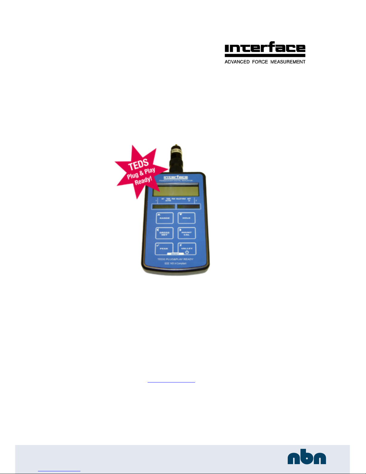
Interface 9320 TEDS Ready Indicator Manual Issue 2.4
6
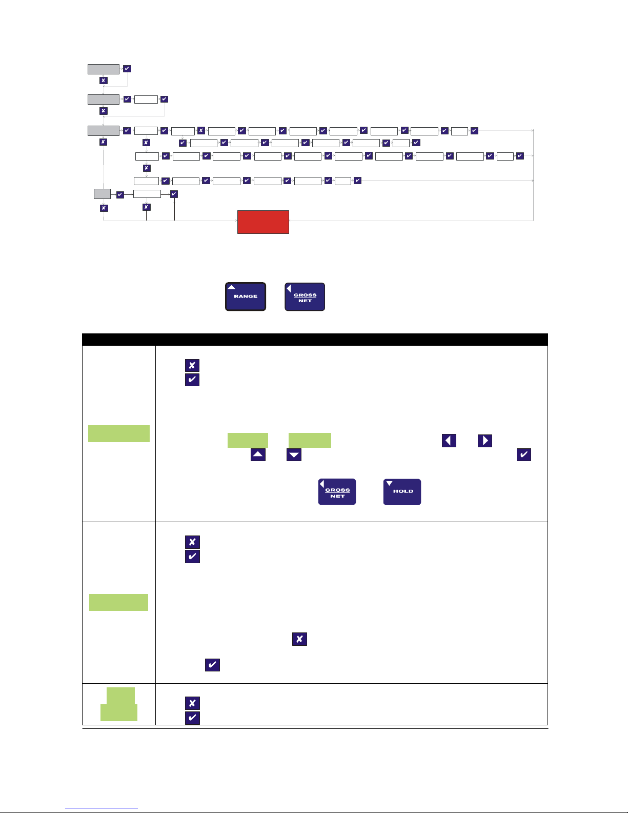
There are six push buttons on the front panel of the 9320, which are available for use in normal operation. Each of
these is described below:
Front Panel Button Function of Button in Normal Operation Mode
To switch the 9320 ON or OFF press and hold the button
The RANGE button allows the user to toggle between two independent
scales. The range that has been selected is highlighted by an annunciator.
The HOLD button allows you to hold/freeze the current display value when
the button is pressed. Pressing the HOLD button again releases the display.
The HOLD annunciator is illuminated when in the HOLD mode, and the
display will flash, to alarm further that the user is not viewing instantaneous
display values.
The GROSS/NET button, when pressed, allows the user to toggle between
displaying the Gross or Net display values. This can be useful in many
applications where it is necessary to display the change in display value from
a certain part of the measurement range. When in NET mode the NET
annunciator is lit. When in GROSS mode, the NET annunciator is not lit.
The SHUNT CAL button allows the user to press this at any point in time.
The standard unit shunts a 100kresistor across the negative excitation and
negative signal connections. If this is performed at the end of the
calibration procedure, then a figure can be noted, so the user can check
calibration accuracy or connection integrity. The button has to be held down
to operate. When held down the SHUNT CAL annunciator is lit and the
display will flash, to alarm further that the user is not viewing instantaneous
display values.
When the PEAK button is pressed the display will show the last Peak
reading. To reset the Peak readings press the PEAK and VALLEY buttons
simultaneously. When in PEAK mode the PEAK annunciator will be lit and
the display will flash, to alarm further that the user is not viewing
instantaneous display values. To turn off Peak mode press the PEAK button.
When the VALLEY button is pressed the display will show the last Valley
reading. To reset the Valley readings press the VALLEY and PEAK buttons
simultaneously. When in VALLEY mode the VALLEY annunciator will be lit
and the display will flash, to alarm further that the user is not viewing
instantaneous display values. To turn off the Valley mode press the VALLEY
button.