NCE UTP User manual

The UTP cab bus panel provides a low cost means of adding
walk around capability to your layout.
A front panel plate and two #6 screws for attaching it to the UTP
printed circuit board are supplied. Note that if you want the LED
at the top of the panel you should install the UTP “upside
down”. This will also keep dust from building on (and inside)
the RJ-12 connectors
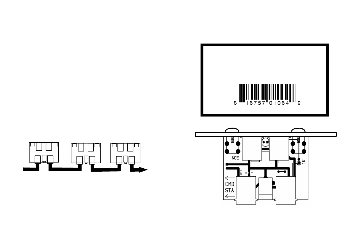
The panel has 4 RJ-12 connectors wired in parallel, two on the
front and two on the rear. Your cab bus can be “daisy chained”
from one panel to the next using the rear connectors. One or
two cabs can then be plugged in to the front connectors. Please
note the “Command Station” side versus the “More UTP
panels” side in the figure below when wiring your panels.
COMMAND
STATION MORE UTP
PANELS
Cab Bus Fascia Panel
Model # UTP
NCE Corporation
82 E Main Street
Webster, NY 14580
Warning: This product contains chemicals known
to the State of California to cause cancer, birth
defects, or other reproductive harm
The UTP cab bus panel provides a low cost means of adding
walk around capability to your layout.
A front panel plate and two #6 screws for attaching it to the UTP
printed circuit board are supplied. Note that if you want the LED
at the top of the panel you should install the UTP “upside
down”. This will also keep dust from building on (and inside)
the RJ-12 connectors
The panel has 4 RJ-12 connectors wired in parallel, two on the
front and two on the rear. Your cab bus can be “daisy chained”
from one panel to the next using the rear connectors. One or
two cabs can then be plugged in to the front connectors.
Please note the “Command Station” side versus the “More
UTP panels” side in the figure below when wiring your
panels.
COMMAND
STATION MORE UTP
PANELS
Cab Bus Fascia Panel
Model # UTP
NCE Corporation
82 E Main Street
Webster, NY 14580
Warning: This product contains chemicals known
to the State of California to cause cancer, birth
defects, or other reproductive harm
INSTALLING AN LED AS A PANEL LOCATOR LIGHT
If you wish an LED can be installed between the two front RJ-12
connectors on the panel to serve as a panel locator light. We
recommend using a T1 sized (.100 inch diameter) LED. Solder
the LED to the bottom of the PC board. Leave enough lead
length to bend the LED over and fit it through the hole in the
front panel. You will also need to solder a 1K ¼ watt resistor in
the two holes marked “1K”.
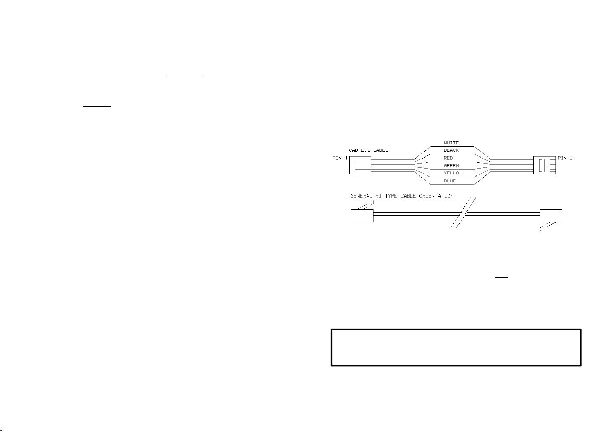
PROPER CAB BUS CABLING
The cables that connect the command station to the UTP and
from UTP to UTP must be wired “straight through” meaning Pin
1 of one connector must be connected to Pin 1 of the other
connector (see figures below). Please note that this is not the
normal telephone cable wiring.The normal wire gauge for RJ-12
cables is #28 or #26. This wire size is sufficient for cab bus
lengths of up to about 30 or 40 feet (10-13 meters).
If your layout requires a cab bus longer than this we suggest
adding extra power to the bus at about 30-40 foot intervals.
This is easily done by plugging a 12-14VDC power supply in to
the 5.5/2.5mm jack on the back of the UTP. The center pin is
positive (+) and the sleeve is negative. We recommend the
NCE P114 (p/n 5240221) or other power supply in the range of
12 to 14 volts DC with a capability of at least ½ to 1 Amp.
IMPORTANT: When adding a power supply to the UTP
you MUST cut the circuit trace marked with an “X” on
top of the circuit board.

INSTALLING AN LED AS A PANEL LOCATOR LIGHT
If you wish an LED can be installed between the two front RJ-12
connectors on the panel to serve as a panel locator light. We
recommend using a T1 sized (.100 inch diameter) LED. Solder
the LED to the bottom of the PC board. Leave enough lead
length to bend the LED over and fit it through the hole in the
front panel. You will also need to solder a 1K ¼ watt resistor in
the two holes marked “1K”.
PROPER CAB BUS CABLING
The cables that connect the command station to the UTP and
from UTP to UTP must be wired “straight through” meaning Pin
1 of one connector must be connected to Pin 1 of the other
connector (see figures below). Please note that this is not the
normal telephone cable wiring.The normal wire gauge for RJ-12
cables is #28 or #26. This wire size is sufficient for cab bus
lengths of up to about 30 or 40 feet (10-13 meters).
If your layout requires a cab bus longer than this we suggest
adding extra power to the bus at about 30-40 foot intervals.
This is easily done by plugging a 12-14VDC power supply in to
the 5.5/2.5mm jack on the back of the UTP. The center pin is
positive (+) and the sleeve is negative. We recommend the
NCE P114 (p/n 5240221) or other power supply in the range of
12 to 14 volts DC with a capability of at least ½ to 1 Amp.
IMPORTANT: When adding a power supply to the UTP
you MUST cut the circuit trace marked with an “X” on
top of the circuit board.


