NCM NCM-1550-EM30 User manual

NCM-1550-EM30 (1550nm Externally
Modulated Optical Transmitter)
Operating Manual

NCM-1550-EM30 (1550nm externally modulated optical transmitter) operating manual
- 1 -
Table of Contents
Table of Contents...................................................................................................... - 1-
Safety Instruction......................................................................................................- 2 -
1. Overview............................................................................................................... - 3 -
1.1 About This Manual ......................................................................................- 3 -
1.2 Product Description ..................................................................................... - 3-
1.3 Product Applications....................................................................................- 4 -
2. Technique Parameters ........................................................................................... - 5-
2.1 Optical Parameters.......................................................................................- 5 -
2.2 Model Test Indicators................................................................................... - 5-
2.3 Test Condition..............................................................................................- 6 -
2.4 Technical Data Sheet.................................................................................... - 6 -
3. Panel Interface and Menu System Description.....................................................- 7 -
3.1 Front Panel...................................................................................................- 7 -
3.1.1 Indicator Description ......................................................................... - 7-
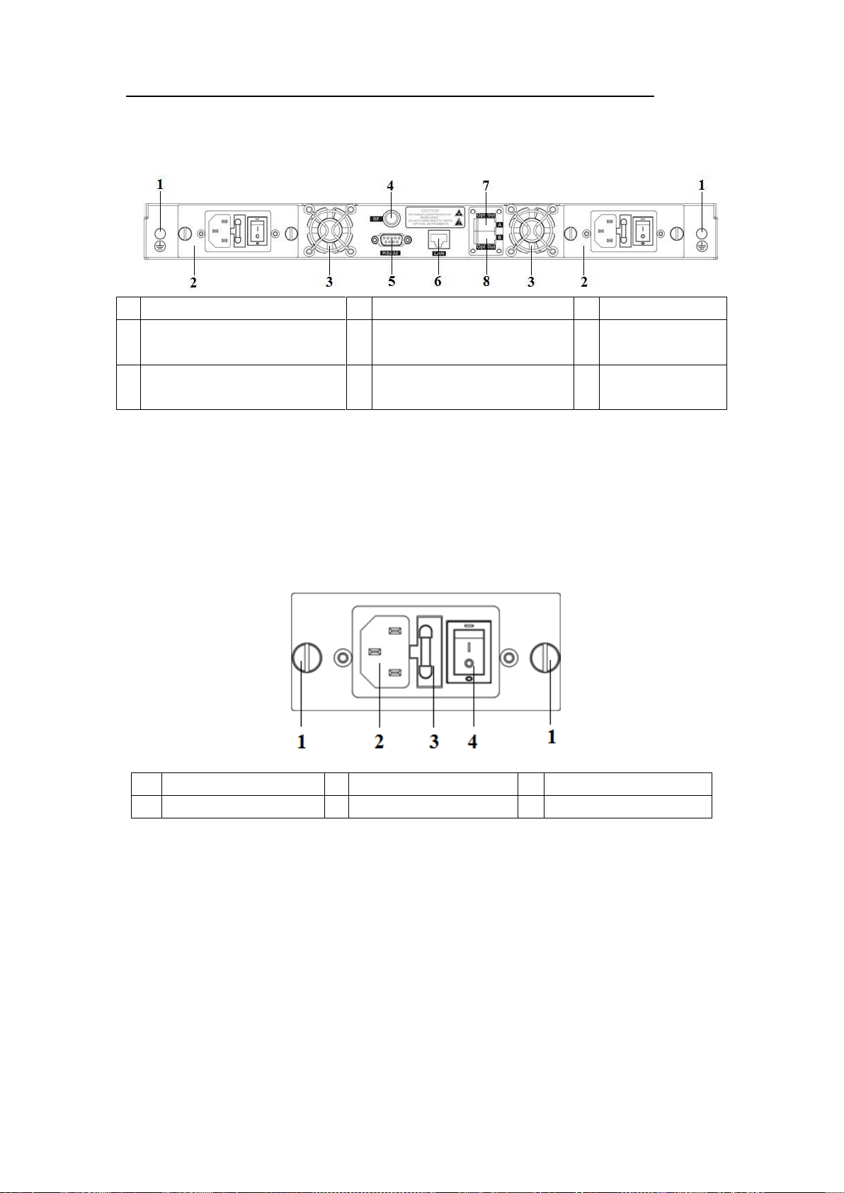
3.2 Rear Panel....................................................................................................- 8 -
3.3 Power Module.............................................................................................. - 8 -
3.3.1 220V Power Module..........................................................................- 8 -
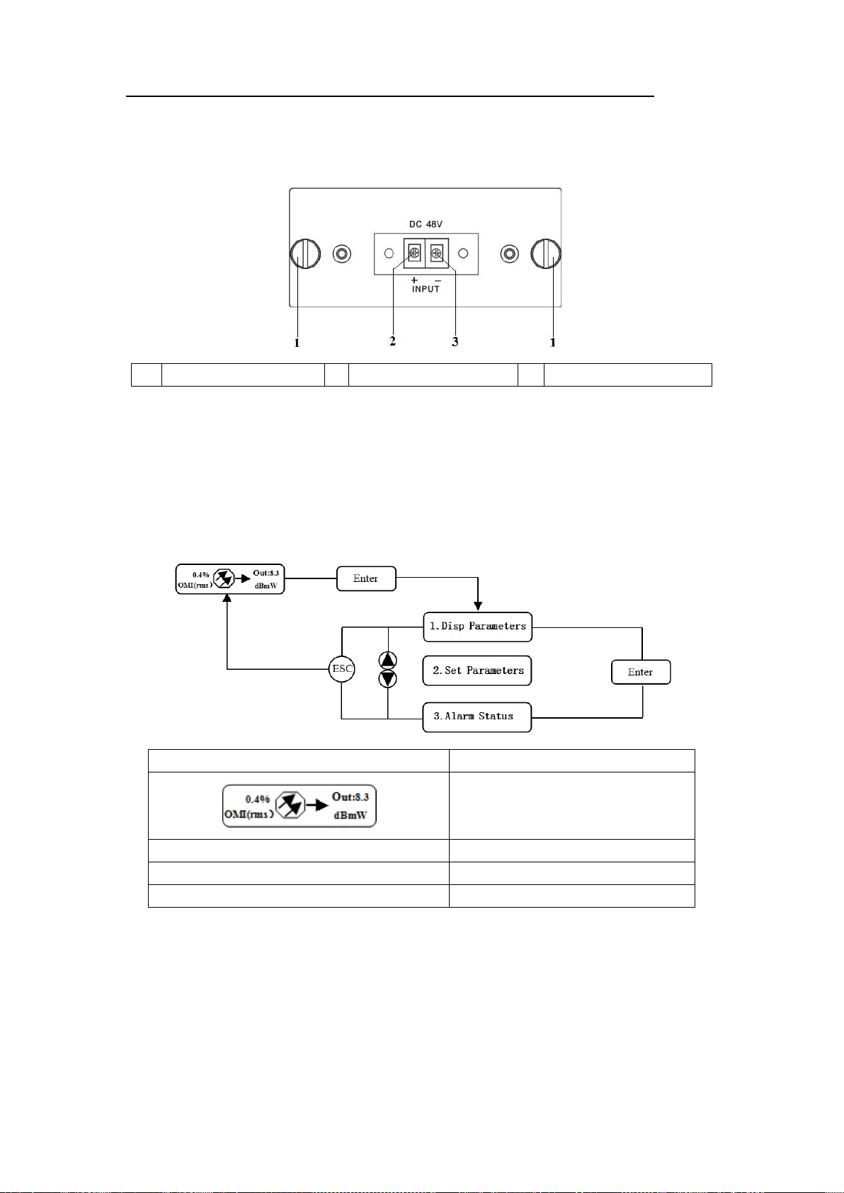
3.3.2 48V Power Module............................................................................- 9 -
3.4 Menu Operation ...........................................................................................- 9 -
3.4.1 Main Menu......................................................................................... - 9 -
3.4.2 Display Menu................................................................................... - 10 -
3.4.3 Set Menu .......................................................................................... - 11-
3.4.4Alarm Menu.....................................................................................- 12 -
3.4.5AGC Mode.......................................................................................- 12 -
3.4.6 MGC Mode......................................................................................- 12 -
3.4.7 FrequencyAdjust ITU in DWDM ...................................................- 13 -
3.4.8 SBS Suppression Adjustment ..........................................................- 13 -
4. Installing the NCM-1550-EM30 Optical Transmitter............................................-
14 - 4.1 Receiving and Inspecting...........................................................................-
14 -
4.2 Precautions.................................................................................................- 14 -
4.3 Mounting NCM-1550-EM30........................................................................- 15 -
4.3.1 Mounting the EM30 in the Rack...................................................... - 15-
4.3.2 Connecting the RF Cables ............................................................... - 15-
4.3.3 Connecting the Optical Fiber Cables...............................................- 15 -
4.3.4 Connecting the Ethernet Cable ........................................................ - 16-
4.3.5 Connecting Power............................................................................- 16 -
5. Communication Setup......................................................................................... - 17-
5.1 RS232 Communication Interface Description...........................................- 17 -
5.2 Set up the Hyper Terminal.........................................................................- 17 -
5.3 Operating Parameters Configuration .........................................................- 19 -
5.4 Remote Monitoring: SNMP....................................................................... - 22 -

NCM-1550-EM30 (1550nm externally modulated optical transmitter) operating manual
- 2 -
5.5 WEB Network Management...................................................................... - 23-
6. Maintenance and Troubleshooting...................................................................... - 25-
6.1 Cleaning Fiber Optic Connectors............................................................... - 25-
6.1.1 Cleaning Patch Cord or Pigtail Fiber Optical Connectors ............... - 25 -
6.2 Troubleshooting ......................................................................................... - 26 -
6.3 After-sales Service Description..................................................................- 27 -
6.4 Disclaimer..................................................................................................- 27 -
Safety Instruction

NCM-1550-EM30 (1550nm externally modulated optical transmitter) operating manual
- 3 -
1.
Overview
1.1
About This Manual
This instruction manual is a complete guide to install and operate the (1RU)
NCM-1550-EM30 series 1550nm externally modulated optical transmitter. Please
read the entire manual before beginning installation.
This manual applies to NCM-1550-EM30 series externally modulated optical
transmitter.
•
Chapter 1 gives general information about the NCM-1550-EM30 series 1550nm
externally modulated optical transmitter.
•
Chapter 2 describes the complete technical specifications of NCM-1550-EM30.
•
Chapter 3 describes the front/rear panel interfaces and menu system.
•
Chapter 4 tells you how to install NCM-1550-EM30 series externally modulated
optical transmitter.
•
Chapter 5 tells you the communication setting of NCM-1550-EM30.
•
Chapter 6 describes maintenance and what to do in the event of problems.
1.2
Product Description
NCM-1550-EM30 series optical transmitter is a 1550nm DFB laser externally
modulated transmitter. It is specially developed for the CATV signal that satisfies
HFC network, and the long-distance transmission of cable phone and cable data.
Working principle
NCM-1550-EM30 series transmitter has 7 function modules: RF control, DFB
laser, optical modulator, SBS control, CSO control, communication/display control
and power supply.
Automatic gain control circuit (AGC) or manual gain control circuit (MGC)
amplifies the RF signal. AGC or MGC control makes the optical modulator maintain a
suitable input level. Use the detected RF root-meansquare(RMS)-total power to
calculate the optical modulation index(OMI).
In general we recommend using the AGC function, and special users can use the
MGC function to adjust the CNR/CSO/CTB performance indexes.
The core of transmitter is the optical modulator. The 1550nm signal input the
optical modulator, make the laser intensity changed follow the external RF signal
voltage, and then generate the AM optical signal.

NCM-1550-EM30 (1550nm externally modulated optical transmitter) operating manual
- 4 -
Stimulated Brillouin Scattering (SBS) occurs, when the optical input power is
greater than a certain threshold value. SBS generate the lower frequency
backscattered light which will attenuate the transmission light and return to the laser
while destroying its performance. Causing optical power fluctuation, generates large
noise, and seriously deteriorates the system carrier to noise ratio (CNR). To improve
the SBS threshold, NCM-1550-EM30 series optical transmitter adopts SBS control
technology which is independent researched and developed by ourselves. The
threshold value can be set up to 19dBm.
The optical modulator has a two-way optical signal output. Parts of that signal
are routed to an InGaAs photodiode. This detection of the optical signal has two
functions:
1)
Detect whether the laser is normal working. Once the output optical power is
2dB lower than standard power, alarm will be set off.
2)
Detect CSO distortion to optimize the bias point of the optical modulator. For
working normal the detector circuit needs at least two carrier signal inputs with an
interval of 24MHz. There is a CSO initialization program in the boot process. If the
CSO install failed, the RF indicator will flash red, see details in 6.2Troubleshooting.
Block Diagram
1.3
Product Applications
•High-performance long-distance transmission
•High-power distribution network
•Redundancy loop architecture
•FTTx network
•RFOG application
•DWDM network

NCM-1550-EM30 (1550nm externally modulated optical transmitter) operating manual
- 5 -
2.
Technique Parameters
2.1
Optical Parameters
Item
Unit
Value
Optical Wavelength
nm
1545~1560 (or specified by the user)
Side-mode Suppression ratio
dB
>30
Relative Intensity Noise
dB/Hz
<-160
Wavelength Adjustment
Range
GHz
+/-50GHz
Optical Power
dBm
2*7, 2*8, 2*9, 2*10
SBS Threshold Value
dBm
+13~+19 (Continuously adjustable)
Laser Linewidth
MHz
0.3
2.2
Model Test Indicators
Test Model
C42
D59
D84
D84
Channel Plan
CENELEC42
PAL D59
PAL D84
PAL D
Channel Number
TV/FM/QAM64
42/0/0
59/0/0
84/0/0
30/0/48
Bandwidth Noise
5
5
5
5
CNR Tx/Rx
55.5
54.0
52.5
54.5
CNR Link 1
55.0
53.5
52.0
54.0
CNR Link 2
53.0
52.5
50.5
52.5
CNR Link 3
50.5
50.5
49.0
51.0
CSO Tx/Rx and Link 1
64
65
65
70
CSO Link 2
63
65
65
70
CSO Link 3
62
64
63
65
CTB
65
65
65
68

NCM-1550-EM30 (1550nm externally modulated optical transmitter) operating manual
- 6 -
2.3
Test Condition
First stage
EDFA
First
paragraph
fiber length
Second
stage
EDFA
Second
paragraph
fiber length
RX
SBS
(dBm)
Tx/Rx
No
No
No
no
0dBm
13.5
Link 1
No
35km
no
no
0dBm
13.5
Link 2
16dBm
65km
no
no
0dBm
16
Link 3
13dBm
50km
13dBm
50km
0dBm
13.5
Rx with 8 pA/ÖHz input noise current density; EDFA with 5dB noise figure; RF input level at 80
dBμV / TV channel;
2.4
Technical Data Sheet
Item
Unit
Technical Parameters
RF range
MHz
47~1003
RF flatness
dB
+/-0.75
RF return loss
dB
>16
RF input impedance
Ω
75
RF input connector type
F type
Rated input level
dBµV
80
Input level range
dBµV
78~96 (AGC mode, modulating signal)
AGC control range
dB
+3~-3
MGC adjustable range
dB
0~15
Optical connector
SC/APC, FC/APC
Operating temperature
°C
-5~45
Storage temperature
°C
-30~+70
Power Source
Specification
V
90~265VAC
36~72VDC
Consumption
W
≤60
Dimension
mm
483(L) × 455(W) × 44(H)
Total Weight
kg
5.5

NCM-1550-EM30 (1550nm externally modulated optical transmitter) operating manual
- 7 -
3.
Panel Interface and Menu System Description
3.1
Front Panel
1
Power indicator
2
AGC indicator
3
RF modulation degree
indicator
4
Laser indicator
5
LCD
6
ESC key
7
UP key
8
DOWN key
9
Enter key
10
-20dB RF input test port
11
RF input port (or on the
rear panel, optional)
12
Optical output interface A (or
on the rear panel, optional)
13
Optical output interface B (or
on the rear panel, optional)
3.1.1 Indicator Description
Power indicator
One power supply
LED yellow
Two power supplies
LED green
AGC indicator
AGC mode
LED green
MGC mode
LED off
RF modulation degree
indicator
Normal
LED green
Abnormal
LED flash red
Laser indicator
Bias current, cooling current and
output power are all normal
LED green
At least one of bias current,
cooling current and output power
is abnormal
LED flash red

NCM-1550-EM30 (1550nm externally modulated optical transmitter) operating manual
- 8 -
3.2
Rear Panel
1
Ground stud
2
Power module
3
Fan
4
RF input port (or on the front
panel, optional)
5
RS232 interface
6
LAN interface
7
Optical output interface A (or
on the front panel, optional)
8
Optical output interface B (or
on the front panel, optional)
3.3
Power Module
3.3.1 220V Power Module
1
Mounting screws
2
220V power outlet
3
Fuse
4
Power switch

NCM-1550-EM30 (1550nm externally modulated optical transmitter) operating manual
- 9 -
3.3.2 48V Power Module
1
Mounting screws
2
+ Positive terminal block
3
- Negative terminal block
3.4
Menu Operation
3.4.1 Main Menu
Displayed parameters
Comments
Boot display
1.Disp Parameters
Menu one: Display parameters
2.Set Parameters
Menu two: Set parameters
3.Alarm Status
Menu three: Alarm status

NCM-1550-EM30 (1550nm externally modulated optical transmitter) operating manual
- 10 -
3.4.2 Display Menu
Displayed
parameters
Comments
Displayed
parameters
Comments
Laser Output
Output optical power
+24V Read:
+24V monitor voltage
Laser Bias
Laser current
+12V Read:
+12V monitor voltage
RF CSO
CSO monitor voltage
-12V Read:
-12V monitor voltage
RF Source
The current RF signal source
LASER:
Laser status
Laser Cooling
Cooling current
SBS Module
Temp:
SBS module temperature
OMI(rms)
Total modulation degree
BOX Temp:
Overall temperature
RF Mode
RF control mode
MCU Temp:
MCU temperature
AGC
Adjusted value with AGC mode
S/N:
Serial number
MGC
Adjusted value with MGC mode
Version:
Version number
+5V Read:
+5V monitor voltage
Work Time:
Work time
-5V Read:
-5V monitor voltage

NCM-1550-EM30 (1550nm externally modulated optical transmitter) operating manual
- 11 -
3.4.3 Set Menu
Displayed parameters
Comments
Remarks
Select RF input signal source
Select RF input signal
Analong&digital full analog signal or analog
and digital mixed signal
Digital full digital signal
Set RF MODE
Set RF control mode
MGC and AGC two modes selectable
Set AGC
Set MGC
Set RF adjusted value
Adjustable range 0~15dB with MGC mode
Adjustable range -3~+3dB with AGCmode
Set SBS Suppression
Set SBS value
Range 13~19dBm, 0.5dB stepping
Set ITU
Set optical wavelength
Range ±50GHz
Set Channel Distance
Set channel distance
6MHz, 7MHz, 8MHz
Set LASER
Set laser status
ON/OFF
Set IP Address
Set IP address
Set Mask
Set subnet mask
Set Gateway
Set gateway
Set Trap1 Address
Set trap1 address
Set Trap2 Address
Set trap2 address
Set Buzzer Alarm
Set buzzer alarm
ON/OFF
Restore Factory Cfg
Restore factory
settings

NCM-1550-EM30 (1550nm externally modulated optical transmitter) operating manual
- 12 -
3.4.4 Alarm Menu
The displayed alarm content
Comment
RF IN Status
HIGH(LOW)
The RF input signal is high (low)
Laser Bias
HIGH(LOW)
The laser bias current is high (low)
Laser TEC
HIGH
The laser cooling current is high
Output Power Status
HIGH(LOW)
The output optical power is high (low)
-5V Status
HIGH(LOW)
The -5V voltage is high (low)
+5V Status
HIGH(LOW)
The +5V voltage is high (low)
+12V Status
HIGH(LOW)
The +12V voltage is high (low)
-12V Status
HIGH(LOW)
The -12V voltage is high (low)
+24V Status
HIGH(LOW)
The +24V voltage is high (low)
Laser
OFF
The laser is off
CSO Initialization failed
The CSO initialization is failed
Power invalid
LEFT(RIGHT )
The left (right) power is invalid
3.4.5 AGC Mode
This mode is the recommended mode and also the standard operation.
The optical transmitter will automatically adjust to the optimal gain while the input
level is in the working range (see the technical data sheet). And the specified OMI
(rms) modulation index will be automatic gain control.
3.4.6 MGC Mode
Special users, who need to adjust system CNR/CSO/CTB performance indexes to
satisfy the specified requirements, can use this mode. The amplification gain
attenuation range 0-15dB.
(Not recommend).

NCM-1550-EM30 (1550nm externally modulated optical transmitter) operating manual
- 13 -
3.4.7 Frequency Adjust ITU inDWDM
To help DWDM applications, NCM-1550-EM30 can adjust optical wavelength. The
adjustable range is ±100GHz, 50GHz stepping. The button on the front panel or the
Ethernet interface will complete the adjustment.
λ=c/f, c is the speed of light. It is the constant value.
c=299792458m/s, f is the frequency, its unit is Hz; eg frequency 193400GHZ, the
corresponding wavelength is 1550.12nm.
In the 1545-1560nm band, the frequency distance and the wavelength distance is very
similar to linear relationship.
50GHz frequency distance reflects to wavelength is very approximate to 0.4nm width;
As the same, 100GHz frequency distance reflects to wavelength is very approximate
to 0.8nm width.
3.4.8 SBS SuppressionAdjustment
SBS value is very important in 1550nm long-distance transmission system. Stable
continuous coherent light source, add +6 dBm optical power in the standard single
mode fiber may occur SBS phenomenon. Ultrahigh SBS threshold will reduce CNR
and CSO low-frequency indicators.
High SBS threshold will also influence self phase modulation (SPM) and reduce
high-frequency CSO indicator.
When meet the conditions, as far as possible to use a low threshold SBS.

NCM-1550-EM30 (1550nm externally modulated optical transmitter) operating manual
- 14 -
4.
Installing the NCM-1550-EM30 Optical Transmitter
4.1
Receiving and Inspecting
As you unpack your unit, inspect the shipping container and equipment for damage.
Save the shipping material for future use. If the container or the equipment is
damaged, notify both the freight carrier and us.
4.2
Precautions
Heed the following precautions when working with the NCM-1550-EM30.
Warning
Read the installation instructions before connecting the system to
the power source.
Attention
Avant de brancher le système sur la source
d'alimentation,consulter les directives d'installation.
Warnung
Vor dem Anschließen des Systems an die Stromquelle die
Installationsanweisungen lesen.
Warning
The plug-socket combination must be accessible at all times,
because it serves as the main disconnecting device.
Attention
La combinaison de prise de courant doit être accessible à tout
moment parce qu'elle fait office de système principal de
déc onnexion.
Warnung
Mit Wechselstrom betriebenes Modell: Der Netzstecker muss
jederzeit leicht zugänglich sein.
CAUTION: To protect yourself from potential injury and to protect the
equipment from further damage, do not perform any
operational tests if the equipment appears to be damaged.

NCM-1550-EM30 (1550nm externally modulated optical transmitter) operating manual
- 15 -
4.3
Mounting NCM-1550-EM30
4.3.1 Mounting the EM30 in theRack
Mounting the EM30 in the standard 19 inch equipment rack:
1.
Place the equipment in the rack.
2.
Use four screws fixed the mounting lug on the NCM-1550-EM30 front panel to
the rack.
3.
Reliably ground the equipment. The ground terminal is on the rear panel.
4.
Visually inspect each key (button) on the front panel to ensure that it is nottrapped
under the edge of its hole. If a key is trapped, tap the key to enable it to move freely.
4.3.2 Connecting the RF Cables
Verify the RF input F connector type according to the ordering information, then
screw on the matched RF cable.
4.3.3 Connecting the Optical Fiber Cables
NCM-1550-EM30 has two output optical connectors.
1.
Verify the matched NCM-1550-EM30 fiber cable connector type according to the
ordering information.
2.
Verify that the fiber cable connector has been cleaned properly. If the fiber cable
connector needs to be cleaned, follow the cleaning procedure outlined in “Cleaning
Patch Cord or Pigtail Fiber Optical Connectors”.
3.
Verify that the NCM-1550-EM30 optical connector has not been exposed to any
contamination.
NOTE: Any contamination of optical connector can significantly degrade
optical link performance. This degradation will most likely
manifest itself as poor signal-to-noise (SNR) performance.
4.
Note to butt the nick of the connectors and align them accordingly.
DANGER: The fiber carries invisible laser radiation. AVOID DIRECT
EXPOSURE TO BEAM. Never operate the unit with a
broken fiber or with a fiber connector disconnected.

NCM-1550-EM30 (1550nm externally modulated optical transmitter) operating manual
- 16 -
4.3.4 Connecting the Ethernet Cable
You can connect the NCM-1550-EM30 to your TCP/IP network in order to monitor
and control the transmitter remotely. After you complete the installation procedures
described in this chapter, you can use a network management system (NMS) to
monitor and control the NCM-1550-EM30.
To connect the NCM-1550-EM30, you must use a shielded and grounded Category 5
Ethernet cable.
To connect the Ethernet cable:
1.
Connect an Ethernet cable to the transmitter’s RJ-45 Ethernet port and to your
TCP/IP network. The Ethernet port is on the built-in transponder of thetransmitter.
2.
Verify that the green Link LED is illuminated, indicating that there is a connection.
The Link LED is above the Ethernet port on the rear panel.
4.3.5 Connecting Power
The NCM-1550-EM30 is available in an AC power model or DC power model. After
mounting the NCM-1550-EM30 in a rack, follow the power connection procedure
below for the model that you are installing.
The AC-powered NCM-1550-EM30 has two optional power supplies 110V and 220V:
110V power supply has two 110 VAC(50/60 Hz) input connector that requires input
voltage from 90 to 130 VAC, at 50 to 60 Hz single phase. The AC power plug is
located on the rear panel.
220V power supply has two 220 VAC (50/60 Hz) input connector that requires input
voltage from 150 to 265 VAC, at 50 to 60 Hz single phase. The AC power plug is
located on the rear panel.
The DC-powered NCM-1550-EM30 has two -48 VDC input connectors that require
input voltage from -36 to -72 VDC. The DC input connectors are located on the rear
panel.
Turn on the power source. It takes about 60 seconds for all systems to operate. When
connect one power supply, the power indicator is yellow; when connect two power
supplies, the power indicator is green.

NCM-1550-EM30 (1550nm externally modulated optical transmitter) operating manual
- 17 -
5.
Communication Setup
5.1
RS232 Communication Interface Description
Adopt DB9 standard connector, the pin definitions as follow:
1: No Connect
2: TX
3: RX
4: No Connect
5: GND
6: No Connect
7: No Connect
8: No Connect
9: No Connect
The serial communication uses the standard NRZ form, 1 starts bit, 8 data bits, 1
stop bit and the baud rate is 38400.
5.2
Set up the Hyper Terminal
If you have not setup the Hyper Terminal in your Windows system, follow the steps:
Click “start menu →program→accessory→communication→Hyper Terminal”:
This results in the following screen:

NCM-1550-EM30 (1550nm externally modulated optical transmitter) operating manual
- 18 -
Then you input your connection name, such as “SNMP38400”,and choose the serial
port to connect with your equipment. As follows:
Press the “OK” button shows the configuration page of serial port. As follows:
Change the serial port configuration to 38400-baud rate, 8 data bits, no parity bit, 1
stop bit, no data flow control, press the “OK” button, you have set up the Windows
serial port Hyper Terminal.
You can click “file→save” menu to save this configuration of Hyper Terminal for
later using.

NCM-1550-EM30 (1550nm externally modulated optical transmitter) operating manual
- 19 -
5.3
Operating Parameters Configuration
Under the condition of power off, use the serial port lines to connect the RS232 port
with the computer port. Open the Windows Hyper Terminal which you have set up.
Then turn on the power, you will see the page as follows. Enter the password to enter
the configuration interface.
Enter the password, display the following screen:
You can input your command in this page, and then configure the operating parameter
of the application program.
Table of contents
Popular Transmitter manuals by other brands

Williams AV
Williams AV PPA T46 quick start guide

DMP Electronics
DMP Electronics SecuraHub Series Installation and programming guide

F&F
F&F FW-WSO4 quick start guide

MuxLab
MuxLab 500763-TX Quick installation guide

HK Instruments
HK Instruments SIRO Series installation instructions

Baker Hughes
Baker Hughes Panametrics HygroPro user manual