NDX UNIPICK+ User manual

Cell and Tissue Acquisition/Deposition
System with Universal Straddle
Attachment
User Manual
UNIPICK+
Get a Hold of Your Cell
2020
7

Contents
1Introduction 1
2Safety 2
3Components and Accessories 3
4Initial Set Up 4
5Using UnipicK+™7
6UnipicK+™Software –Main Controls 11
7UnipicK+™Software –Automation 16
8Basic Operations 20
9Sample Protocols 30
10 Troubleshooting 40
11 Technical Specifications 41
12 System Performance 42
13 Warranty and Liability 43
14 Contact 43

1
1Introduction
UnipicK+TM, a capillary-based cell and tissue acquisition system, is the key to reliable, precise,
cell and tissue sample acquisition prerequisite for a range of in vitro studies, including cell and
region-specific tissue experimentation and single cell analysis.
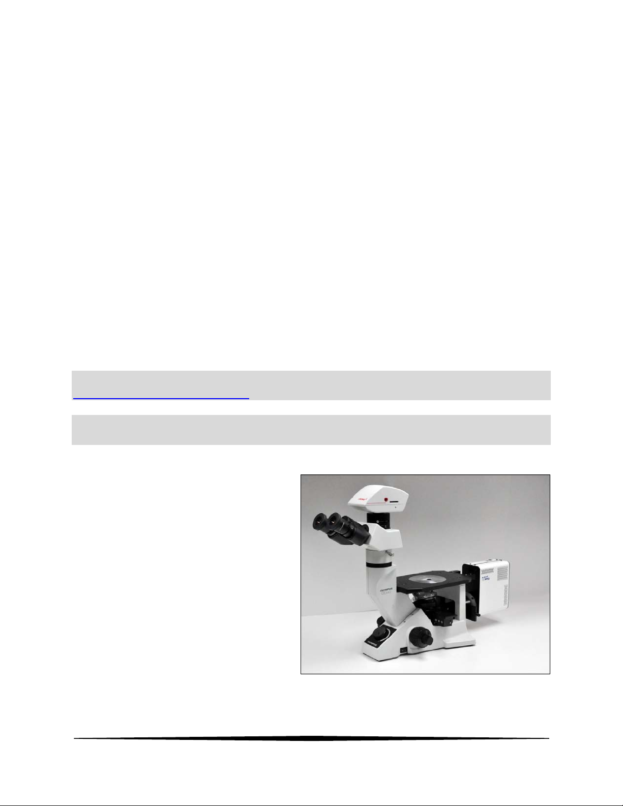
This vacuum-assisted capillary based system is compatible with most inverted microscopes and
allows for rapid and efficient acquisition and deposition of specific cells from adherent cell
cultures based on their morphology, location or fluorescent label. It can also collect single cells
from suspension cell cultures and individual multicellular spheres from three-dimensional (3D)
cell cultures. UnipicK+TM collects cells without compromising cell viability, thus enabling primary
culturing or recultivation of the collected cells.
In addition to the collection of individual cells from culture dishes, UnipicK+TM performs
isolation of single cells and subanatomical regions from various brain tissue samples prepared
by different methods, such as fresh frozen tissue, sucrose treated tissue, and fresh live tissues,
with minimal contamination of surrounding components, while leaving the intracellular
structure and molecules intact. Moreover, it can work with thicker tissue sections up to 500 µm,
suitable for analyses that require large amounts of sample material, such as proteomics.
UnipicK+™may also be used for the collection of micrometric regions of interest from fixed (e.g.
PFA-fixed) and archival tissue specimen, such as formalin fixed paraffin embedded (FFPE) tissue
samples.
Samples collected using UnipicK+TM may be used for a wide range of downstream applications
and techniques used in modern molecular biology, targeting both protein and nucleic acids,
including, but not limited to, quantitative RT-PCR, global gene expression, Next Generation
Sequencing (NGS), epigenetic, and proteomics studies.

2
2Safety
1. Handle glass capillaries with care. Capillaries have sharp tips and can break on or under
skin surface upon contact. It is strongly recommended to always wear goggles and
gloves during handling.
2. Install UnipicK+TM over an inverted microscope, level surface and allow at least 5 inches
of space all around UnipicK+TM.
3. Always use the power supply and cord provided with the unit. If a proper power supply
and cord are not used, product safety performance cannot be warranted.
4. When installing UnipicK+TM, route the power cord away from the microscope frame and
UnipicK+TM unit.
5. Always ensure that the grounding terminal of the UnipicK+TM unit and that of the wall
outlet are properly connected. If the unit is not grounded, NeuroInDx cannot warrant
electrical safety.
6. Never allow any objects to penetrate any openings on the UnipicK+TM unit as this could
result in user injury and damage to the instrument.
7. Do not insert objects into the capillary holder other than filters and disposable capillary
units (DCUs).
8. When UnipicK+TM is not in operation, be sure to turn the power off and disconnect the
power cord from the connector socket of the UnipicK+TM unit or from the wall power
outlet.
9. Dispose used capillaries (DCUs) into a biohazard glass waste container according to
regulations.
Caution: UnipicK+TM components contain hazardous materials. UnipicK+TM should be
disposed according to local regulations.

3
3Components and Accessories
UnipicK+TM (Figure 1) comes equipped with a Universal Straddle that may be fitted over most
inverted microscopes, UnipicK+TM unit (Sampler Head at top with adjustable LED ring light,
Vacuum Line and Electric Cables, and Control Box with vacuum and pressure module), and a
power supply with cord. Ready-to-use Disposable Capillary Units (DCUs) for cell collection and
tissue dissection and filter attachments are sold separately.
Figure 1: Major components of UnipicK+TM:(1) UnipicK+TM Sample Collection Assembly; (2)
Vacuum and pressure Line and Electrical Cables; (3) Slider with micromanipulators; (4)
Universal Microscope Straddle; (5) Front panel of UnipicK+TM Control Box with a touch screen;
(6) Side panel of UnipicK+TM Control Box with a Homing button (top), Sample button (bottom)
and a calibration wheel (green).

4
4Initial Set Up
All necessary components are included in the packing. Make sure that the following items have
been received upon opening the package.
1. UnipicK+TM unit (Head and Control Box) (1)
2. System Alignment Tool (1)
3. Universal Straddle Stand with a bullseye level, a pair of gussets, and short and long
horizontal bars (1)
4. Hex wrenches (2, 2.5, 3, 4, & 5 mm)
5. Power supply and cord (one of each)
Proper installation of all parts is required for UnipicK+TM to work properly. Make sure the
following steps are completed before attempting to use the system. Refer to your microscope
manual for operation specific to the microscope. It is recommended that a crosshair reticle be
placed in the eyepiece before using UnipicK+TM.
NOTE: Instructional video is also available on our YouTube channel:
http://www.youtube.com/NDXInc
NOTE: The following installation of Universal Straddle is shown with UnipicK™model. The
same sequence is used for UnipicK+™instrument.
1. Before placing UnipicK+TM over the
inverted microscope the phase light
must be removed from the
microscope. Refer to the
microscope manual or contact the
microscope manufacturer for
assistance.

5
2. Assemble the Universal Straddle by
attaching a bridge (short or long) to
the curved legs with a pair of
gussets and screws provided with
the unit. DO NOT TIGHTEN THE
SCREWS AT THIS TIME. There are
two possible vertical positions
where the bridge can be attached.
Choose the appropriate height
depending on your microscope.
3. Using a bullseye level (provided)
locate a level surface where the
instrument will be installed. Place
the Universal Straddle on the
surface and level by placing the
bullseye level on the bridge.
Tighten the screws for the gussets
and the sides of the curved legs to
secure all parts in the leveled
position.
4. Loosen the screw on the slider and
place it on the center of the bridge
with the wingnut facing back.
Tighten the screw to secure the
slider on the bridge.
5. Attach the System Alignment Tool
to the slider and place the Universal
Straddle with the Alignment Tool
attached over the microscope. If
necessary, move the mechanical
stage on the microscope to allow
the System Alignment Tool to rest
directly on the microscope stage.
6. Use one hand to hold the System
Alignment Tool in place (red arrow).
Using the other hand, loosen the

6
screws with wingnuts and slide each of the legs down until they all rest on the benchtop.
Once the legs are down on both sides, tighten the screws to secure the legs in place.
7. Looking down onto the System
Alignment Tool, visually align the
center opening on the Tool to the
microscope objective lens (red
arrow).
8. Remove the System Alignment Tool
and carefully attach the UnipicK+™
Head to the slider and secure by
tightening the screws.
NOTE: Current assembly is shown with UnipicK™, the same sequence is used for UnipicK+™.
Power supply and cord
Connect the power supply and the cord. Plug the female cord plug into the power jack located
in the rear wall of the UnipicK+TM side chassis and plug the power cable into the outlet. Use
only the supplied power supply and cord.

7
5Using UnipicK+™
5.1 Terminology
Starting position: Highest vertical position for the DCU; the initial position when the
unit is first turned on and capillary has been mounted or after it is
reset.
Home position: Calibration of Collecting/Dissecting or Dispensing position of the
DCU tip determined by the user. Homing is performed prior to
every collection/dissection and dispensing procedure.
Standby position: 1 mm above the Home position for Acquisition mode. DCU will
be lifted to Standby position after each single acquisition or
dispensing event. DCU returns to Standby position after each
sampling until the Home position (Acquisition plane or Dispensing
plane) or the system has been reset.
5.2 Power
To turn power on, turn the black switch on the back panel of the Control Box. At this point the
screen and a green indicator light will turn on (Figure 2). To turn off the unit, press the switch
again.

8
5.3 Filter and DCU attachment
Turn the UnipicK+TM head 90˚ counterclockwise to expose the male luer connector (Figure 3).
Holding the outer rim of the filter, connect the female luer lock connector of the filter to the
male luer connector on the UnipicK+TM Head. Do not overtighten the filter, as this will damage
its female luer lock. Next, attach a DCU to the filter.
Caution: DCU consists of two parts, the hub base with a female luer lock connector
and a glass capillary component. Always handle a DCU by the hub base to avoid
injury and damage to the capillary.
5.4 X-Y control
To center the tip of the DCU in the field of view, use the manual dials (Figure 3) on the linear
stages/micromanipulators at the base of the UnipicK+TM head where it mounts to the Universal
Straddle.
5.5 Positioning
To position the tip of the DCU along the z-axis, use the green calibration wheel (Figure 2-5) to
move DCU up and down. A single click will move the DCU by 1.5 µm. When the wheel is moved
fast, the DCU will move at a faster rate (default set at 150 µm/sec) specified in the Settings
window of the UnipicK+™software (please, see Section: UnipicK+TM Software).
5.6 Home for the Acquisition and Dispensing planes
Use the green Calibration wheel (Figure 2-5) to set the Home position for Acquisition plane or
Dispensing plane, i.e. the desired position of the DCU’s tip on the z-axis for sample acquisition
or dispensing. When the capillary tip comes in contact with the tissue surface or cells or
desired dispensing plane (e.g. surface of the liquid in a sample tube), press the green calibration
wheel (Figure 2-5). When the Home position for the acquisition mode is designated, the
Acquisition plane icon will turn green and DCU will move 1 mm above that position on the z-axis
to the Standby position. For the dispensing mode, the Dispensing plane icon will turn green and
DCU will move to the Starting position.

9
5.7 Vacuum level and duration control
The vacuum or pressure levels may be controlled from 0 to maximum of 70 kPa and the impulse
duration may be set from 100 ms to maximum of 1 s (see UnipicK+ Software section).
Depending on the sample and the desired result, various vacuum/pressure levels and impulse
duration may be used. We recommend testing these parameters prior to any
collection/dispensing procedure.
5.8 Sample
After the Home positions have been set, pressing the lower Sample button (Figure 2-4) will
initiate sample collection or deposition by bringing the DCU down to the Home position and
activating the vacuum or pressure impulse at the selected strength and duration.
Figure 2: UnipicK+TM control box includes: (1) Touch screen with controls; (2) Power
indicator (green logo button); (3) Retract (upper blue button) to automatically moves the
capillary above the plate to allow collection from different wells without recalibration procedure.
Subsequent pressing of the Retract button brings the DCU back to a previously calibrated
Standby position in acquisition mode; (4) Sample (lower green button): for cell/tissue collection
and deposition; (5) DCU Positioning and Calibration (green wheel): to bring the DCU up or down
towards the stage and set up Acquisition and/or Deposition planes.

10
Figure 3: UnipicK+TM sample collection Head (1). The following components are shown: (2)
Shield covering green horizontal calibration light used for DCU tip identification during
calibration procedure; (3) Vacuum line and electrical cable. The Head should be turned full 90˚
for disposable capillary (DCU) attachment/removal. The x-y position of the DCU is controlled by
the knobs on the linear stages/micromanipulators (4 and 5). The knob for micromanipulator on
the front of the stage control the front to back movement of the DCU (4), and the one on the left
side of the bottom stage control the side to side movement.

11
6UnipicK+™Software - Main Controls
UnpicK+™software operates the instrument via the touch screen. It offers controls for
calibration sequences, sample collection, dispensing, fixed tissue microdissection and single cell
adhesion force measurements. The following section describes the main menus, operations,
icons and their function. For further instructions on how to use these controls in a specific
application, advance to “Initial Training Exercises with UnipicK+™.”
6.1 Startup
Main menu is represented by six
icons/options: Calibration –controls for
setting stand by positions for both
Acquisition and Deposition modes;
Acquisition and Dispensing –controls for
collection and sample deposition
parameters, respectively; Fixed tissues –
controls for working with fixed tissue
specimen; and Settings –general controls
of the UnipicK+™;
6.2 Calibration
Left side of the menu has two sliding bars
for the control of the main (left) and
calibration (right) light intensities. Next to
the sliding bars are controls for DCU’s
vertical movement (along z-axis). Single
arrows apply slower motion (1000 µm/sec)
and triple arrows move DCU in a fast mode
(2,500 µm/sec). Internal diameter of DCU
(from 10 to 100 µm) may be selected using
the icons in the middle of the screen.
NOTE: Internal diameter of DCU must be selected if adhesion measurements are performed
or the value of applied force is desired.

12
The following controls/icons are present on the right side of the Calibration window:
-Acquisition plane icon sets the plane where sample collection is to take place;
-Dispensing plane icon sets the plane where collected sample(s) will be
deposited;
-The Retract feature remembers the most recent Home (Acquisition or
Dispensing plane) position. It lifts the DCU to the Starting position and 15mm
below the starting position in the Calibration Window. In Acquisition and
Dispensing Windows, it will allow the user to move between Acquisition or
Dispensing plane, Standby, and the initial Starting positions.
The icons on the right side of the window are found on all function windows to allow easy
movement from one window to another. The icon of a window that is currently in use appears
in grey.
-Home icon returns to the Main menu
6.3 Acquisition
The window offers controls for sample
collection, including vacuum strength and
impulse duration. It also keeps track of
how many acquisitions were performed
since the most recent calibration, time
used, and force applied for each sample
collection. Left side of the menu has the
same sliding bars for light intensity control.
The following controls/icons are present on the right side of the Acquisition window:
-Collect icon is specific for the Acquisition window. It activates a single sample
acquisition sequence.
-Green Calibration icon indicates that Calibration procedure (identification of
Acquisition plane) was already performed

13
-Auto-dispensing icon takes you to the plate set up and auto-dispensing menu
(Available for instruments equipped with a motorized stage. Please contact
NeuroInDx representative for details.)
-When activated (turned green) this icon indicates that auto-dispensing process
is ON (Available for instruments equipped with a motorized stage. Please
contact NeuroInDx representative for details.)
NOTE: Acquisition plane may be changed by bringing the DCU to the desired location using
the Green calibration wheel (Figure 2-5) then pressing the wheel. Same adjustments for the
Dispensing plane may be performed directly within Dispensing window
6.4 Dispensing
The window offers controls for sample
deposition including pressure strength,
and impulse duration. Like Acquisition
window, it keeps track of the number of
dispensing events that were performed
and the elapsed time since the most recent
calibration. It also displays the force
applied for each sample deposition. Left
side of the menu has the same sliding bars
for light intensity control, and the right
side contains the main controls.
NOTE: We recommend using low pressure for dispensing starting from 2 kPa and longer
duration time starting from 100 to 200 msec. Excessive pressure will result in a rapid sample
dispensing spurting the DCU contents. If not sufficient, pressure and time duration may be
adjusted for optimal sample deposition.
The following controls/icons are present on the right side of the Dispensing window:
-Dispense icon is specific for the Dispensing window. It activates a single sample
dispensing sequence.

14
6.5 Fixed Tissues
This window provides manual and
automatic pulse modes for acquisition of
ROIs from fixed tissues such as formalin
fixed paraffin embedded or PFA fixed
tissue specimen. Pulse is an application of
vacuum impulse with predefined duration
and strength without lifting of the DCU tip
from the tissue surface, which allows
mixing the digestion liquid inside the
capillary barrel.
The following controls/icons are present on the right side of the Fixed Tissues window:
-Manual pulse mode. Manual procedure initiates the collection sequence at any
given time with possible incorporation of individual pulses as desired during
the incubation (digestion) process.
-Automatic pulse mode. For automatic process, incubation time and specific
number of pulses during incubation period could be preset prior to initiation of
a digestion procedure. At the end of digestion, the software initiates a
standard acquisition sequence using predefined vacuum strength and impulse
duration.
Collection procedure can be repeated for the next ROI using the same DCU or collected sample
could be deposited in the desired sample tube using UnipicK+ deposition mode.
6.6 Adhesion Strength
This function allows for the comparative
estimation of single cell adhesion strength,
e.g. how much force is required to lift a cell
from the surface. Two output
measurements are provided for the
comparative analysis - “TOTAL FORCE” and
“FINAL FORCE”. Both values are based on
the algorithm of the RAMP function. TOTAL
FORCE is defined as a sum of all forces
corresponding to the total number of
executed pulses. FINAL FORCE represents

15
the force used for the last and the highest vacuum pulse in the ramp process. APPLIED PULSES
is the total number of pulses executed.
The following controls/icons are present on the right side of the Adhesion window:
-Ramp function represents a specific number (NUM PULSES) of vacuum
impulses starting with a predefined initial vacuum strength (VACUUM, kPa)
raised by a predefined interval (INTERVAL, kPa) for each subsequent pulse.
-STOP icon may interrupt the RAMP process at any time. Current values for
executed pulses (APPLIED PULSES), TOTAL FORCE and FINAL FORCE will be
given.
6.7 Settings
Left half of the screen allows for the
selection (from left to right) of main light,
calibration light, NDX logo light, and screen
light intensities. Three icons on the top
right permit selection of DCU vertical
movement speed for the fast mode of the
calibration wheel.
Two icons on the lower right part of the
screen offer a choice of the main
calibration wheel direction to move DCU down: counterclockwise (CCW) and clockwise (CW)
directions. The default distance for standby position during acquisition is 1mm from the
acquisition plane; however, this can be changed to a shorter distance on this page.
The following controls/icons are present on the right side of the Settings window:
-CCW and CW icons permit selection of the main calibration wheel
direction for moving DCU up or down
-Icons to select DCU movement speed

16
7UnipicK+™Software –Automation (optional)
Auto-collection and auto-dispense features allow the user to automatically collect and dispense
multiple samples into PCR tubes. These features require a motorized stage (please contact
NeuroInDx representatives for specifications). The process entails Plate setup (7.1), Dispensing
parameters selection (7.2), and Target selection (7.3).
7.1 Plate set up
After initiating the auto dispensing icon
(6.3), a plate set up and auto-dispensing
window will appear. The left side of the
window represents 48 well sample holder.
To set up a plate, move the automated
stage to position the farthest back left well
on the sample holder to align the center of
the well with your DCU tip position on the
x-y plane using the motorized stage. The
top left corner well position on the
window will be blinking. Tap the blinking
top corner well position. The circle will
stop blinking and turns dark blue when the
stage position is calibrated.
Now move the stage to position the front
most right well on the sample holder to
align with your DCU position on the x-y
plane. Tap the blinking bottom right well.
The circle will stop blinking and change
color to dark blue. Tap the OFF icon to ON.
Plate calibration is complete (dark blue).
The collected samples will now be
deposited from top left well to the bottom
right well in a consecutive order.
Entire columns and rows may be
deselected if necessary, by tapping on the
corresponding triangle. For example, the
image on the right shows that first four
columns and a bottom row were

17
deselected, and only dark blue wells are remaining for depositing samples.
NOTE: Similarly, individual wells may be deselected (tapped once) or prioritized (tapped
twice) for the deposition process.
NOTE: Before using the auto dispensing function, make sure to set the pressure on the
Dispensing window at a minimum of 2kPa. However, the pressure applied for the deposition
will be the value set on the Plate Set up/auto-dispensing window.
In addition to the plate set up, this menu offers options for capillary rinsing while depositing a
sample. It permits multiple rounds of collection and dispensing within the same tube to ensure
that DCU contents do not remain in the capillary. The number of such washing cycles is defined
by tapping arrows above or below the blue dispensing icon on the top right of the window.
Each tap corresponds to one wash cycle. The total number of cycles is shown in the lower left
corner of the wash icon. Vacuum and pressure together with duration for washing cycle is set
using the arrows in corresponding parameters.
The following controls/icons are present on the right side of the Plate set up window:
-Auto-collect screen icon. Tapping on this icon opens an Auto-collect window
-Return to Dispensing window
-Return to Acquisition window
7.2 Auto-dispensing
Dispensing maybe directly initiated from
the Plate Set up/auto-dispensing window
using a Dispense icon. Alternatively,
dispensing will occur automatically into
designated location after each acquisition
step if auto-dispensing droplet icon is
activated. Note that AUTODISP icon is
green indicating that the plate set up has
been performed.

18
The progress of deposition will be shown
in the auto-dispensing window that may
be accessed any time by tapping the green
AUTODISP icon. Wells where collected
samples were deposited will be indicated
with green. For example, the image on the
right shows that already four samples
were deposited in the first four wells. Four
washing cycles were used for dispensing.
7.3 Auto-collection
Auto-collect screen icon opens the Auto-
collection window, where up to eight
targets may be preselected for automatic
collection and deposition into designated
locations (specified in the Auto-deposition
window, 7.1). Acquisition parameters for
selected targets are specified in the
Acquisition window (6.3). Tapping on the
AUTODISP icon would then open the Plate
set up/auto-dispensing window with an
Auto-collect icon.
Select either POOL or SINGLE for pooling collections into a single tube or singly collect and
dispense (used for single cell collection). Move the stage to position the target in alignment
with the DCU tip position on the x-y plane. Tap PRESELECT, and the position will populate the
list under POSITION.
Tap the AUTODISP icon to go back to the Auto-dispense window. Tap the OFF icon on the right
of the window to set to ON. Now the Auto-dispense function has been enabled and will turn
green. Tap the red arrow icon on the window, which will take you to the Acquisition window.
The Plate icon should appear in green. Tap the Eye drop icon next to it to activate the auto-
dispense function. To start collection, tap the Collect icon. The system will begin its cycle and
will collect eight preselected targets depositing them into designated locations with the wash
cycle specific in the plate set up/auto-dispense window.
Make sure that the system has completed the full cycle and come to a complete stop (the stage
should have returned to the last collection position). Tapping the ALL Red circle (icon) on the
Auto-collection window will clear the previously selected positions.
Table of contents
Popular Laboratory Equipment manuals by other brands

ROMANOFF
ROMANOFF Vac-U-Vest 12 product manual

Hach
Hach AS950 AWRS Basic Installation and Maintenance

Agilent Technologies
Agilent Technologies 979 Replacement manual

Sartorius
Sartorius Cubis MCE Series operating instructions

Zadro Health Soultions
Zadro Health Soultions NANO-UV DUAL SCANNER user manual

Leica
Leica DFC500 Operating Notes