NEO IP/GSM Technical Handbook
Document number: NE41 09002-02 v2.0
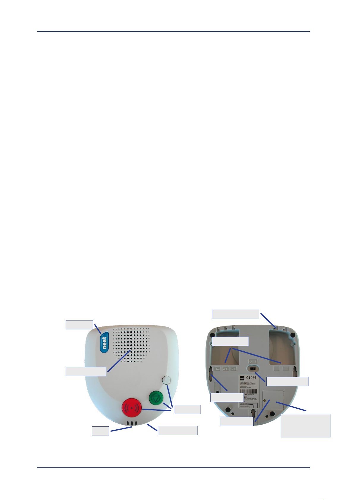
Theemblemdiersonthethetwomodels
• Blue emblem - NEO IP or NEO IP with GSM backup.
• Black emblem - NEO GSM.
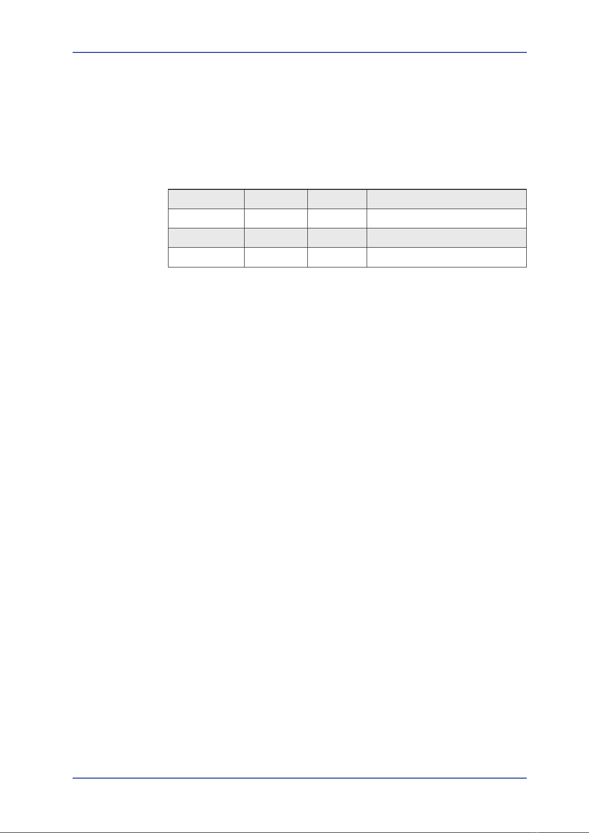
1.3.2 Connectors
Thereare4connectorslocatedintwowellsattheboomside.Allconnectors
are of modular (western) type.
Connector Type Marking Funcon
Power RJ22 AC AC adaptor or NPU
Line RJ11 LINE Firmware upgrade
Internet RJ45 IP Ethernet
External input RJ45 AUX External inputs
Table 1. Connectors on the NEO IP/GSM
1.3.3 Powerswitch
BypungtheswitchintheboomoftheunitinposionI, the unit is turned
ON.Whenturnedon,theunitstartsup,iniatesandgoesintonormalmode,i.e.
it is ready to receive and transmit alarms. The startup lasts about 10 seconds and
isnishedwhentheredAlarmbuonislitsteadily.
Pleasenotethatitisn’tenoughtotaketheACplugout,toshutotheunit.The
unitwillthenusethebackupbaeryaspowersource.Toturnosettheswitch
to 0.
1.3.4 Cable channels
Attheboomsidetherearevesmallcablechannelstoxthecables.Usethese
foraniceanddyinstallaon.
1.3.5 Key holes
Therearethreekeyholesforwallmounngoftheunit.Therearethreepossibili-
estomounttheunit.
• Usethetwoholesatthesidesandhangtheunitwiththebuonsdown
• Usethetwoholesatthesidesandhangtheunitwiththebuonsup
• Let the unit hang in the middle hole and use the others for steering. The but-
tons have to be upwards.
The holes are designed to be used together with screws heads with a diameter of
7-8mm.Thescrewheadshallbeapproximately4mmoutofthewallforbestt.
Introducon
8 of 56