Vers le
transmetteur
Câble de téléchargement sériel
Vers le port
sériel de
l'ordinateur
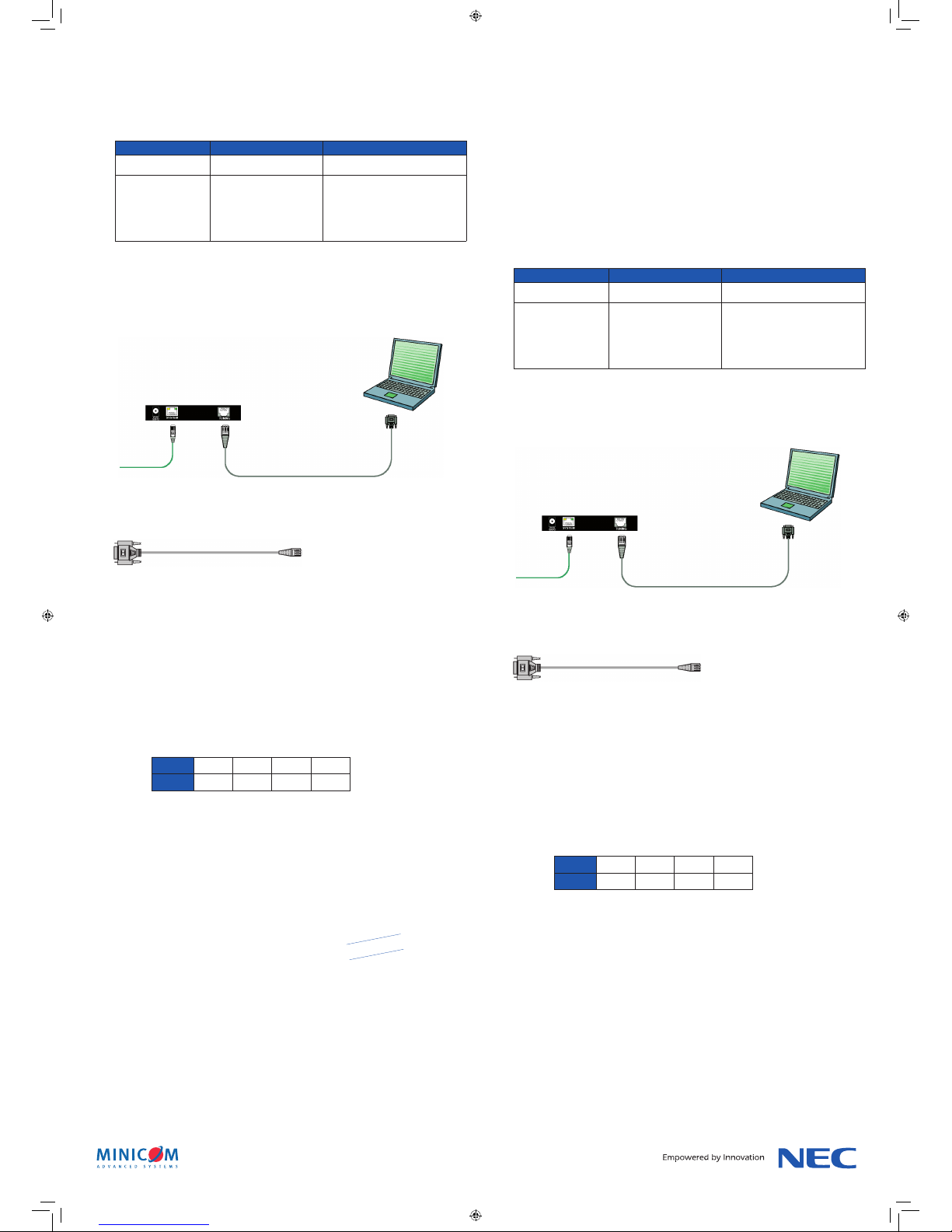
Fig. 1 Liaison entre le câble de téléchargement sériel et le récepteur Long
Fig. 2 Câble
Câble de téléchargement sériel
Zum
Transmitter
Serielles Download-Kabel
Zum
seriellen
Computer-
Abb. 1 Verbinden des seriellen Download-Kabels mit dem Receiver Long
Appareil Voyant Fonction
Transmetteur / émetteur Façade - Vert Indicateur de fonctionnement
Récepteur / Récepteur
Long
Dos – prise système RJ45.
Vert / jaune
Vert – indicateur Marche.
Lumière jaune continue – l’appareil est
relié au système.
Lumière clignotante jaune – l’appareil
communique avec l’unité émettrice.
NEC Display Solutions Europe GmbH
Landshuter Allee 12-14 · D-80637 Munich · P.O. Box 190665 · D-80606 Munich
Phone +49 (0) 89 99 699 – 0 · Fax +49 (0) 89 99 699 – 500
see more: www.nec-display-solutions.com
All hardware and software names are brand names and/or registered trademarks of the respective manufacturers.
All rights reserved. All specifications are subject to change without notice. October 2007.
5) Assurez-vous que le récepteur est introduit dans le bon sens. Le port Tuning doit se trouver sur le
dessus et l’étiquetage du connecteur ne doit pas être tourné vers le bas.
Introduisez délicatement le récepteur dans le logement jusqu’à ce que vous sentiez un déclic. N’usez
pas de la force !
6) Utilisez pour fixer le récepteur les vis qui maintenaient le cache.
7) Fixez à nouveau la poignée en veillant à ce que les vis soient bien serrées (moment de 1,39 – 1,89 Nm).
8) Reliez le câble CATx avec les prises correspondantes du système émetteur et des récepteurs/récepteurs
Long.
CONSIGNES DE SERVICE ET D’ENTRETIEN
1) Voyants
Voyants et fonctions des composants du système :
2) Tuning (réglage)
Le système doit être réglé de manière à obtenir une qualité d’image optimale.
Vous pouvez procéder au réglage du récepteur/des récepteurs Long à l’aide de l’utilitaire depuis
l’emplacement de l’émetteur ou des récepteurs. Si vous procédez directement au tuning depuis les
récepteurs, cela vous permet de suivre parallèlement l’opération à l’écran.
Vous trouverez dans le mode d’emploi DS Vision des informations relatives au tuning depuis
l’emplacement de l’émetteur.
Pour procéder au tuning depuis les récepteurs, procédez comme suit :
Reliez le câble de téléchargement sériel à la prise de tuning correspon-
dante sur le récepteur et à la prise sérielle de l’ordinateur sur lequel
l’utilitaire est installé. Voir l’illustration ci-dessous.
Vous trouverez ci-dessous une illustration du câble de téléchargement sériel DS Vision (fourni avec
l’émetteur).
Vous trouverez des informations détaillées concernant le tuning et la configuration du système
dans le mode d’emploi correspondant DS Vision fourni avec l’émetteur/le transmetteur.
EN CAS D’ERREUR
1) Le voyant vert est éteint.
a. Le récepteur a-t-il été correctement inséré dans le logement ? Les vis sont-elles bien serrées ?
b. Le moniteur est-il en marche ?
2) Le voyant est allumé, mais il n’y a pas d’image.
a. Avez-vous sélectionné l’entrée « Option » ?
b. Bien que ce soit peu probable, vérifiez que les interrupteurs DIP se trouvent dans la bonne position
au dos de l’appareil derrière le connecteur noir 60 broches.
Les interrupteurs DIP sur les platines RCU-NEC DS Vision 3000 doivent être réglés comme suit :
3) Image floue
a. La résolution est-elle bien réglée ?
- NEC MultiSync®LCD4020, LCD4620: 1360 x 768
- NEC M40, M46 et MultiSync®LCD6520: 1920 x 1080
b. Le moniteur a peut-être été réglé sur une autre taille d’écran. Appuyez sur la touche « Size » de la
télécommande jusqu’à ce que la mention « Standard » apparaisse en haut à droite de l’image.
c. Le tuning de l’appareil a-t-il été effectué correctement ? (Voir à ce propos « Consignes de service
et d’entretien / Tuning ».)
BETRIEBS- UND WARTUNGSHINWEISE
1) LED-Anzeigen
LED-Anzeigen und Funktionen der im Gesamtsystem enthaltenen Geräte:
2) Tuning
Zur Erzielung der bestmöglichen Bildqualität muss das System getunt werden.
Sie können den Receiver bzw. die Receiver Long mit Hilfe der entsprechenden Service Utility von der
Broadcaster-Position oder von den Receivern selbst aus tunen. Wenn Sie das Tuning direkt von den
Receivern aus vornehmen, hat dies den Vorteil, dass Sie den Vorgang parallel am Bildschirm verfolgen
können. Informationen über das Tuning von der Broadcaster-Position aus finden Sie in der DS Vision-
Bedienungsanleitung.
Verfahren Sie beim Tuning von der Receiver-Position aus wie folgt:
Verbinden Sie das serielle Download-Kabel mit dem Tuning-Anschluss des
Receivers und dem seriellen Anschluss eines Computers, auf dem die
Service Utility installiert ist. Siehe folgende Abbildung.
Nachfolgend eine Illustration des seriellen DS Vision Download-Kabels (im Lieferumfang des Broadcasters
enthalten):
Einzelheiten zum Tuning und zum Einrichten des Systems finden Sie in der DS Vision-
Bedienungsanleitung, die sich im Lieferumfang des Broadcasters / Transmitters befindet.
FEHLERBEHEBUNG
1) Die grüne LED leuchtet nicht.
a. Wurde der Receiver korrekt in den Einschubschacht eingeführt?
Sind die Schrauben richtig angezogen?
b. Ist das Display in Betrieb?
2) Die LED leuchtet, aber es wird kein Bild angezeigt.
a. Haben Sie als Eingang “Option” ausgewählt?
b. Obwohl sehr unwahrscheinlich, überprüfen Sie bitte auch, ob sich die DIP-Schalter auf der
Geräterückseite hinter dem schwarzen 60 PIN-Connector in der richtigen Position befinden.
Die auf den DS Vision 3000 RCU-NEC-Boards enthaltenen DIP-Schalter müssen wie folgt eingestellt
sein:
3) Unscharfes Bild
a. Wurde die richtige Auflösung eingestellt?
- NEC MultiSync®LCD4020, LCD4620: 1360 x 768
- NEC M40, M46 und MultiSync®LCD6520: 1920 x 1080
b. Das Display ist möglicherweise für eine andere Bildgröße eingestellt. Drücken Sie auf Ihrer
Fernbedienung so oft die Taste “Size”, bis oben rechts im Bild die Anzeige “Standard”
eingeblendet wird.
c. Wurde die Geräteeinheit ordnungsgemäß getunt (siehe hierzu den Punkt “Betriebs- und
Wartungshinweise / Tuning”)?
DS Vision 3000 récepteur intégré Short, VGA only, NEC
DS Vision 3000 récepteur intégré Long, VGA only, NEC
CONSIGNES D’INSTALLATION
1) Éteignez complètement le moniteur en actionnant l’interrupteur ou bien débranchez complètement
l’appareil du courant.
2) Le récepteur doit être inséré dans le logement prévu à cet effet. Celui-ci se trouve sur la gauche du
moniteur près de la poignée.
3) Retirez la poignée en défaisant les deux vis à empreinte cruciforme.
4) Retirez le cache qui recouvre le logement en défaisant les deux vis à empreinte cruciforme.
français
Position 1 2 3 4
Status Off Off On On
Position 1 2 3 4
Statut Off Off On On
Geräteeinheit LED Function
Transmitter / Broadcaster Frontseite - Grün Betriebsanzeige
Receiver / Receiver Long Rückseite - RJ45
Systemanschluss.
Grün / Gelb
Grün – in Betrieb.
Leuchtet konstant gelb – Gerät ist mit
dem System verbunden.
Gelbes Blinklicht –
Gerät kommuniziert mit Sendereinheit.
Abbildung 2 Kabel
Serial Download-Kabel