NEC CHIEF K3F220 User manual

CHIEF Stand
K3F220/K3G220 (2x2)
K3G320 (3x2)
EX241UN / -H Multi-Screen
Installation Manual

CHIEF STAND INSTALLATION MANUAL | USER’S GUIDE
Contents
General Information and Cautions. . . . . . . . . . . . . . . . . . . 3
Chapter 1 Removing the Bezel 4
Purpose . . . . . . . . . . . . . . . . . . . . . . . . . . . . . 4
How to Remove the Bezel . . . . . . . . . . . . . . . . . . . . . . 5
Chapter 2 2 x 2 Multi-Monitor Installation (K3F220/K3G220) 6
Model K3F220 (Self-Standing) . . . . . . . . . . . . . . . . . .6
Model K3G220 (Desk Mounted) . . . . . . . . . . . . . . . . . . 7
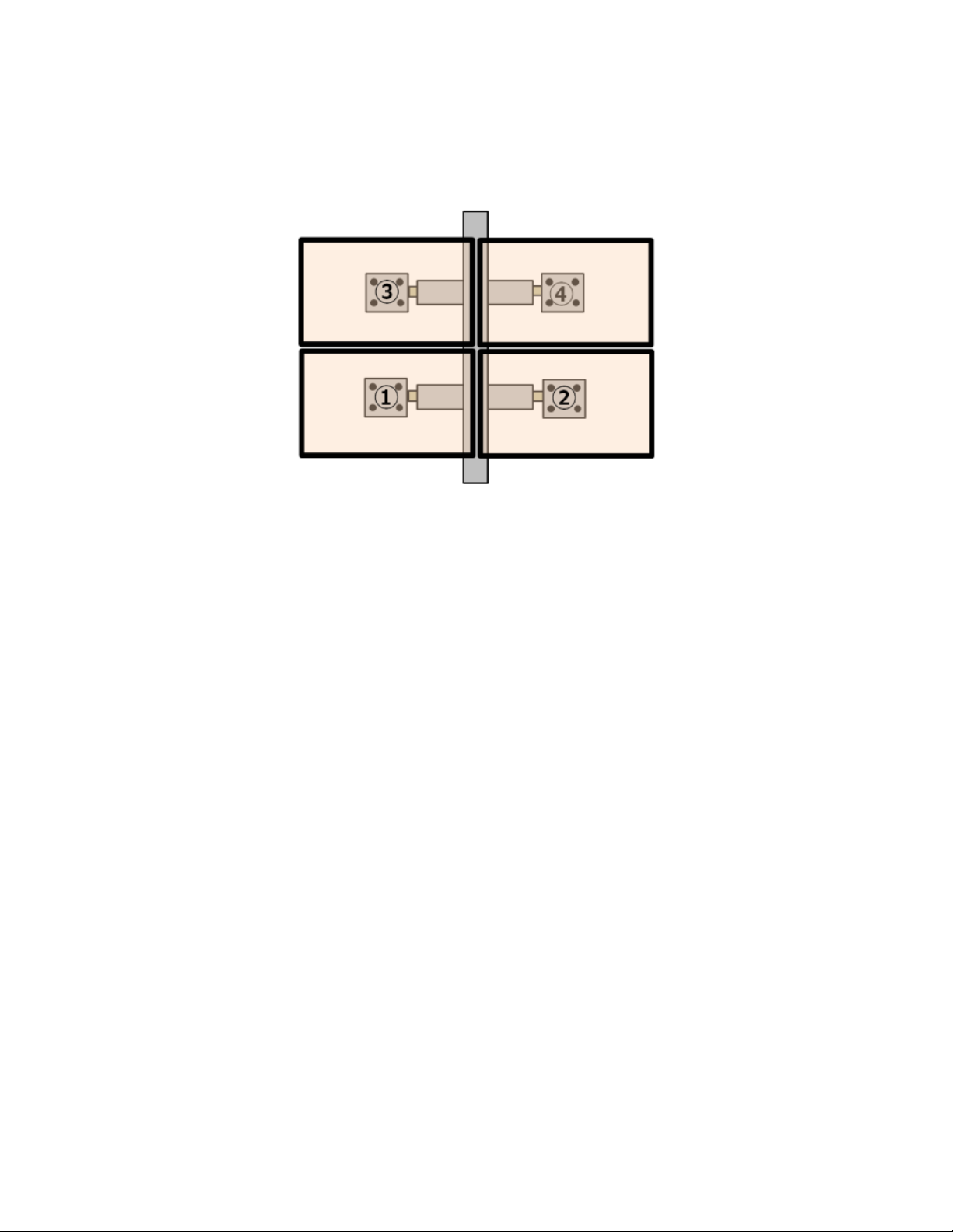
Overview . . . . . . . . . . . . . . . . . . . . . . . . . . . 8
Installing the Lower Left and Lower Right Monitors . . . . . . . . . . . . 9
Set the Vertical Arm Position . . . . . . . . . . . . . . . . . . . 9
Attach the Monitors . . . . . . . . . . . . . . . . . . . . . . 10
Set the Horizontal Position . . . . . . . . . . . . . . . . . . . 11
Installing the Upper Left and Upper Right Monitors . . . . . . . . . . . 13
Adjust Tilt / Swivel / Pivot . . . . . . . . . . . . . . . . . . . . . 16
Tilt the Upper Monitors . . . . . . . . . . . . . . . . . . . . 16
Face the Monitors Inside. . . . . . . . . . . . . . . . . . . . 17
Cable Connection Example . . . . . . . . . . . . . . . . . . . . 18
Cable Management. . . . . . . . . . . . . . . . . . . . . . 18
Chapter 3 3 x 2 Multi-Monitor Installation (K3G320) 19
Model K3G320 (Desk Mounted) . . . . . . . . . . . . . . . . . 19
Overview . . . . . . . . . . . . . . . . . . . . . . . . . . 20
Installing the Center Monitors . . . . . . . . . . . . . . . . . . . 21
Set the Center VESA Plates Position . . . . . . . . . . . . . . . 21
Attach the Lower Center Monitor . . . . . . . . . . . . . . . . 24
Attach the Upper Center Monitor . . . . . . . . . . . . . . . . 25
Installing the Lower Left and Lower Right Monitors . . . . . . . . . . . 27
Set the Vertical Arm Position . . . . . . . . . . . . . . . . . . 27
Attach the Lower Left and Lower Right Monitors . . . . . . . . . . 29
Set the Lower Left and Lower Right Horizontal Position. . . . . . . . 30
Installing the Upper Left and Upper Right Monitors . . . . . . . . . . . 31
Completed Setup . . . . . . . . . . . . . . . . . . . . . . 32
Adjust Tilt / Swivel / Pivot . . . . . . . . . . . . . . . . . . . . . 33
Facing the Monitors Towards Center . . . . . . . . . . . . . . . 33
Tilt Down the Upper-Center Monitor (Not Recommended) . . . . . . . 34
Cable Connection Example . . . . . . . . . . . . . . . . . . . . 35
Cable Management. . . . . . . . . . . . . . . . . . . . . . 36
Chapter 4 Unifying Multi-Picture Quality 37
Copyright © 2017 NEC Display Solutions, Ltd.
The content of this manual is furnished for informational use only, is subject to change without notice, and should not be
construed as a commitment by NEC Display Solutions. NEC Display Solutions assumes no responsibility or liability for
any errors or inaccuracies that may appear in this manual.
Document revision: February 2017
CHIEF® is a registered trademark of Milestone AV Technologies.

General Information and Cautions
¾Installation experience is necessary.
• The CHIEF stands have exibility in connecting parts with monitor sets. Installation experience is necessary
for achieving proper alignment and setup.
• At least 2 people are needed to properly install the monitors to the CHIEF stand. One person to hold the
monitors after attaching them while adjustments are made to the arms and VESA plates.
¾For information about the EX241UN and EX241UN-H refer to the monitor's user manual.
• Safety and cautions for handling the monitors are in their appropriate usage manuals.
• Mounting and usage is the customer's and installation specialist's responsibility, failure to comply with the
safety and handling instructions in the user's manual could result in voiding the warranty.
| 3
CHIEF STAND INSTALLATION MANUAL | USER’S GUIDE

Chapter
CHIEF STAND INSTALLATION MANUAL | USER’S GUIDE
Purpose
Removing the monitor's bezel provides a more seamless wall image in multi-monitor installations.
Inactive Area: Single Unit
With Bezel Without Bezel Dierence
Top / L / R 5.38mm 3.93mm
1.45mm
Bottom 8.02mm 6.57mm
Inactive Area: Adjacent 2 Units (2 x Single Unit)
With Bezel Without Bezel Dierence
Top / L / R 10.76mm 7.86mm
2.90mm
Bottom 16.04mm 13.14mm
1 Removing the Bezel

REMOVING THE BEZEL | 5
CHIEF STAND INSTALLATION MANUAL | USER’S GUIDE
How to Remove the Bezel
Caution:
• Use extreme care when performing the steps to remove the bezel from the monitor.
• Use a desk or table with a at even surface larger than the size of the monitor screen.
• Place a soft cloth on the surface to protect the glass from scratches and provide padding, and then place the
monitor face down on the soft cloth.
1. Remove the 8 screws holding the bezel in place.
Be careful not to apply pressure when removing the
screws so as not to stress the LCD panel.
2. Insert a spatula (or similar at object) between the
back cover and the bezel.
Separate the hooks starting from the top-left and
proceed clockwise.
3. Remove the bezel and store it.
The bezel needs to be reattached when repacking
the monitor to store or move it. Do not discard the
bezel in trash or recycling.
Note:Removing the bezel from the monitor leaves the edges of the glass unprotected; be careful when moving
and installing the monitors. Do not let the edges of the monitors touch surrounding monitors. Pressure against the
unprotected sides could chip or crack the glass.

Chapter
CHIEF STAND INSTALLATION MANUAL | USER’S GUIDE
Model K3F220 (Self-Standing)
Model: K3F220
Supported Monitor Size: Up to 27 inches
Maximum Weight: 6.8kg x 4 monitors
VESA Hole Pitches: 100x100mm & 75x75mm
Adjustment directions: Up/Down/L/R & Front/Behind (See the illustration below or the CHIEF manual)
35.98
913.8
MAX. MONITOR CENTER
HEIGHT FROM SURFACE
14.66
372.4
MAX DISTANCE
BETWEEN MONITORS
VESA
100 X 100
75 X 75
COMPATIBLE
INTERFACE
TILT ADJUSTMENT
+/-12
22.68
576.0
2.43
COLUMN WIDTH
61.6
0.31
7.9
BASE THICKNESS
39.06
992.2
393.6
15.50
81.0
2.27
COLUMN DEPTH
57.7
3.19
1.21
30.6
15°
34.02
MAX ANGLE
864.1
1.60
40.6
K3F220
DIMENSIONS: INCHES
[M ILLIMETERS]
2 2 x 2 Multi-Monitor Installation (K3F220/
K3G220)

2 X 2 MULTIMONITOR INSTALLATION K3F220/K3G220 | 7
CHIEF STAND INSTALLATION MANUAL | USER’S GUIDE
Model K3G220 (Desk Mounted)
Model: K3G220
Supported Monitor Size: Up to 27 inches
Maximum Weight: 6.8kg x 4 monitors
VESA Hole Pitches: 100x100mm & 75x75mm
Adjustment directions: Up/Down/L/R & Front/Behind (See the illustration below or the CHIEF manual)
36.04
915.3
MAX. MONITOR CENTER
HEIGHT FROM SURF ACE
14.66
372.4
MAX DISTANCE
BETWEEN MONITORS
VESA
100 X 100
75 X 75
COMPATIBLE
INTERFACE
TILT ADJUSTMENT
+/-12
6.4
0.25
BASE THICKNESS
COLUMN WIDTH
61.6
2.43
7.55
191.8
2.28
57.9
2.27
COLUMN DEPTH
57.7
30.6
1.21
985.8
38.81
7.03
178.5
15°
34.02
MAX ANGLE
864.1
1.60
40.6
K3G220
DIMENSIONS: INCHES
[M ILLIMETERS]
(Reference) For K3G220, please attach the stand to the desk following the CHIEF’s “Installation Instructions”.

2 X 2 MULTIMONITOR INSTALLATION K3F220/K3G220 | 8
CHIEF STAND INSTALLATION MANUAL | USER’S GUIDE
Overview
1. Attach the lower left ①and lower right ②monitors.
2. Attach the upper left ③and upper right ④monitors.

2 X 2 MULTIMONITOR INSTALLATION K3F220/K3G220 | 9
CHIEF STAND INSTALLATION MANUAL | USER’S GUIDE
Installing the Lower Left and Lower Right Monitors
Set the Vertical Arm Position
1. Loosen the 4 hex screws Ⓐ/Ⓑfor height
adjustment.
2. Adjust the height of the arms until the left and right
are at the desired height.
3. Tighten the hex screws to x the arms in place.
Make sure the arms are at the same height before
tightening the hex screws.
4. Loosen the hex screw Ⓒand knob Ⓓ of the lower
left and right VESA plates so they can be adjusted
by hand.
ⓘLoosen the hex screw, do not remove it. Ⓒ
Ⓐ
Ⓑ
Ⓐ
Ⓑ
Ⓓ

2 X 2 MULTIMONITOR INSTALLATION K3F220/K3G220 | 10
CHIEF STAND INSTALLATION MANUAL | USER’S GUIDE
5. Adjust the tilt-angle of the VESA plate parallel to the
arm surface. Do not rotate the plate.
6. Tighten the hex screw Ⓒ and knob Ⓓwhen
nished setting the position of the VESA plate.
Attach the Monitors
Two people will be needed to attach the monitors to the stand.
1. EX241UN-H (no stand) – Remove the lower 2
screws from the back of the monitor. Loosen the
upper 2 screws to have some space between the
screw-head and back casing.
EX241UN (with stand) – Have 4 VESA M4 standard
screws available, then set the lower 2 screws with
some space between the screw-head and back
casing.
2. With one person holding the monitor from the front
and one person holding the monitor from the back,
carefully hang the monitor on the VESA plate of the
arm.
Repeat this for the second monitor.
Ⓓ
Ⓒ

2 X 2 MULTIMONITOR INSTALLATION K3F220/K3G220 | 11
CHIEF STAND INSTALLATION MANUAL | USER’S GUIDE
Set the Horizontal Position
1. Loosen the knob Ⓔon the back of the arm for the
left monitor.
2. Move the left monitor so that the edge of the monitor
lines up with the center of the pole.
3. Tighten the knob Ⓔ on the back of the arm to x the
horizontal position.
4. Make sure the monitor does not tilt forward. It should
be completely vertical when viewed from the side.
If necessary, loosen knob Ⓓ and ne tune the
adjustment.
Note:The instructions in this section are for the
monitors to be set up as a at surface. Instructions for
tilting the monitors are under "Adjust Tilt / Swivel /
Pivot" on page 16.
Ⓔ
Ⓓ

2 X 2 MULTIMONITOR INSTALLATION K3F220/K3G220 | 12
CHIEF STAND INSTALLATION MANUAL | USER’S GUIDE
5. Set a spacer (included in the EX241UN box) against
the edge of the lower left monitor.
6. Repeat steps 1-4for the lower right monitor.
Important: One person should hold the spacer while
the other person adjusts the right monitor into position.
A small gap between the monitors is necessary to prevent
damage to the screen, which can expand due to heat.

2 X 2 MULTIMONITOR INSTALLATION K3F220/K3G220 | 13
CHIEF STAND INSTALLATION MANUAL | USER’S GUIDE
Installing the Upper Left and Upper Right Monitors
yFollow the instructions in "Set the Vertical Arm Position" on page 9 for the upper arms.
Make sure to set the upper arms set to a preliminary height with enough room to attach the monitors.
Note:For narrower inactive borders between the upper and lower monitors, install the upper monitors rotated by 180
degrees.
yFollow the instructions for steps 1 and 2 in "Attach the Monitors" on page 10 for placing the upper left and right
monitors.
After the monitors are attached, the upper monitors can be lowered into place following the instructions below.
1. Loosen the 2 hex screws Ⓐ/Ⓑ, for the upper left
arm height adjustment.
One person should hold the monitor to prevent it from
moving while loosening the hex screws.
Ⓐ
Ⓑ

2 X 2 MULTIMONITOR INSTALLATION K3F220/K3G220 | 14
CHIEF STAND INSTALLATION MANUAL | USER’S GUIDE
2. Place a spacer on the top of the lower left monitor.
3. Carefully lower the upper left monitor.
4. After the upper monitor height is in the desired
position, tighten the hex screws to x the arm in
place.
5. Loosen the knob Ⓔon the back of the arm for the
left monitor.
6. Move the upper left monitor towards the center pole
so that the edge lines up with the lower left monitor.
7. Tighten the knob Ⓔ on the back of the arm to x the
horizontal position.
Ⓔ

2 X 2 MULTIMONITOR INSTALLATION K3F220/K3G220 | 15
CHIEF STAND INSTALLATION MANUAL | USER’S GUIDE
8. Loosen the 2 hex screws Ⓐ/Ⓑ, for the upper right
arm height adjustment.
One person should hold the monitor to prevent it from
moving while loosening the hex screws.
9. Place a spacer on the top of the lower right monitor
and on the side of the upper left monitor.
10. Carefully lower the upper right monitor.
11. After the upper monitor height is in the desired
position, tighten the hex screws to x the arm in
place.
12. Follow steps 5and 6above to move the upper right
monitor into position towards the center pole.
Keep the spacers in place while positioning the upper
right monitor.
13. Tighten the knob Ⓔ on the back of the arm to x the
horizontal position.
Ⓐ
Ⓑ

2 X 2 MULTIMONITOR INSTALLATION K3F220/K3G220 | 16
CHIEF STAND INSTALLATION MANUAL | USER’S GUIDE
Adjust Tilt / Swivel / Pivot
Tilt the Upper Monitors
Important: Always have spacers between all of the monitors before adjusting them to prevent the edges of the screens
from touching.
1. Follow the instructions for "Set the Vertical Arm
Position" on page 9 and "Attach the Monitors" on
page 10.
2. After attaching the monitors to the VESA plates,
loosen the knob Ⓓand then tilt the monitor 5~7
degrees to the front.
Do not let the edges of monitors touch. Keep a spacer
between the monitors while adjusting the tilt.
3. Tighten the knob slightly to hold the tilt position while
continuing with the setup.
Ⓓ

2 X 2 MULTIMONITOR INSTALLATION K3F220/K3G220 | 17
CHIEF STAND INSTALLATION MANUAL | USER’S GUIDE
4. Adjust the horizontal position of the VESA plates and
arm angles to align the bottom edge of the upper
monitor with the top edge of the lower monitors.
5. Tighten knobs to x the position of the monitors.
Face the Monitors Inside
Important: Always have spacers between all of the monitors before adjusting them to prevent the edges of the screens
from touching.
1. Follow the instructions for "Set the Vertical Arm
Position" on page 9 for the lower arms.
2. Loosen hex screws Ⓕfor adjusting the swivel of the
lower arms.
3. Adjust the swivel angle between 0~15 degrees
towards the center. Tighten the hex screws Ⓕfully.
4. Follow the instructions for "Attach the Monitors" on
page 10.
5. Follow the instructions for "Set the Vertical Arm
Position" on page 9 to set a temporary position
upper arms.
6. Repeat steps 2-4of these instructions for the upper
monitors.
7. Follow the instructions for "Installing the Upper Left and Upper Right Monitors" on page 13 to nalize the
position of the upper monitors.
ⒻⒻ

2 X 2 MULTIMONITOR INSTALLATION K3F220/K3G220 | 18
CHIEF STAND INSTALLATION MANUAL | USER’S GUIDE
Cable Connection Example
2x2 Monitor
Cable Management
As shown in the picture below, cover the cables using the covers included with the CHIEF stand.

Chapter
CHIEF STAND INSTALLATION MANUAL | USER’S GUIDE
Model K3G320 (Desk Mounted)
Model: K3G320
Supported Monitor Size: Up to 27 inches
Maximum Weight: 6.8kg x 6 monitors
VESA Hole Pitches: 100x100mm & 75x75mm
Adjustment directions: Up/Down/L/R & Front/Behind (See the illustration below or the CHIEF manual)
1.77
15°
MAX ANGLE
17.71
MIN DISTANCE
BETWEEN MONITORS
25.62
MAX. DISTANCE
BETWEEN MONITORS
2.43
COLUMN
7.74 5.00
.96
VESA
100 X 100
75 X 75
COMPATIBLE
INTERFACES
OUTSIDE INTERFACES
CENTER INTERFACES
TILT ADJUSTMENT
+/-10
36.00
MAX MONITOR CENTER
HEIGHT FROM SURFACE
1.21
2.27
COLUMN DEPTH
2.28
7.11
K3G320
DIMENSIONS: INCHES
[M ILLIMETERS]
3 3 x 2 Multi-Monitor Installation (K3G320)

3 X 2 MULTIMONITOR INSTALLATION K3G320 | 20
CHIEF STAND INSTALLATION MANUAL | USER’S GUIDE
(Reference) For K3G220, please attach the stand to the desk following the CHIEF’s “Installation Instructions”.
Overview
1. Set the height of the center VESA plate ①, then VESA plate ②at a measured distance from ①.
2. Attach monitors ①and ②.
3. Set the set the upper and lower arms at temporary heights.
4. Attach monitors in order of ③, ④, ⑤, then ⑥.
5. Fix the arm height, move the monitors to the center, ne tune adjust tilt/swivel/pivot simultaneously.
This manual suits for next models
2
Table of contents
Other NEC TV Mount manuals
Popular TV Mount manuals by other brands

Chamberlain
Chamberlain 041A5281-1 quick start guide

PEERLESS
PEERLESS SLWS410/BK Installation and assembly

Alphason
Alphason Alpha Series manual

peerless-AV
peerless-AV KIL740 instructions

Shakespeare Electronic
Shakespeare Electronic 484 installation instructions

Deltaco Gaming
Deltaco Gaming GAM-101 instruction manual