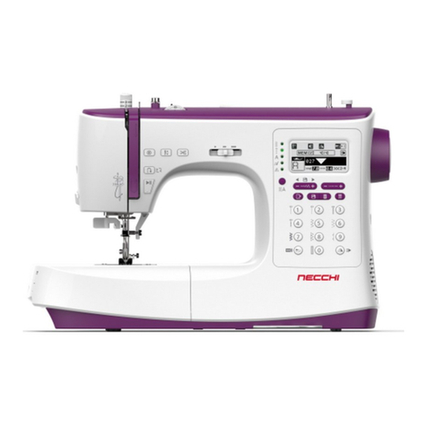
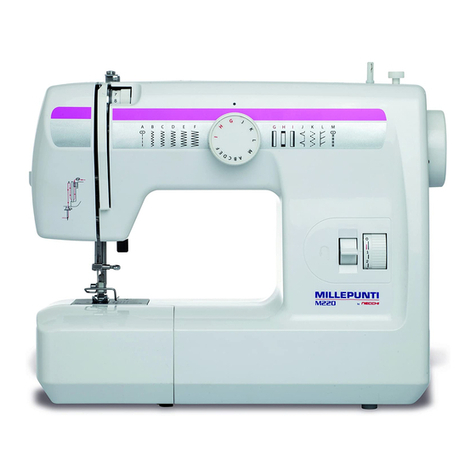
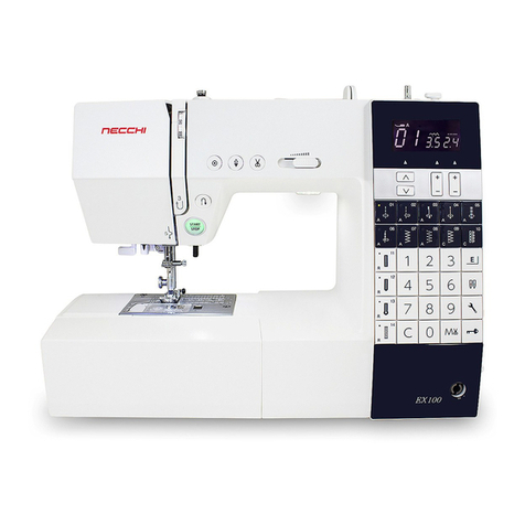
Necchi Automatic Supernova Ultra Mark 2 User manual

I
..
@
NECCHI Societa
per
A:z:ioni
• P1vi1 ( :t1ll1 )
• Simb. 9961270/
GB
ind
.
11
NECCHI
,
automatic
supernova
ultra
mark
2
Instructions
for
the
use
and
maintenance

.
LIST
OF
CONTENTS
Chapter 1
GENERAL
INSTRUCTIONS
1.
To
insure
perfect
functioning
of
machine
. . . . . . .
2.
Recommended
needle a n d
thread
sizes . .
3.
J:o
insert
needle
4.
To
thread
machine
. . .
5.
To
thread
needle
with
threader
6.
To
wind
empty
bobbin
7.
"To
remove
bobbin
case
8.
To
insert
.
bobbin
into
bobbin
case . . . . .
9.
To
insert
bobbin
case
to.
To
adjust
tension
11.
To
regulate
stitch
length
· .
12
.
To
start
sewing
13.
To
drop
feed
dog
14.
To
remove
work
from ma-
chine . .
...
.
15
.
To
change
the
position
of
multiple
needle
plate
16.
To
connect
machine
to
local
electricity
supply
.
17.
To
.
run
machine
18.
Lighting
. . . .
19.
To
replace
light
bulb
20.
Maintenance
of
machine
a)
Oiling
..
. .
b)
To
remove
and
.replace
the
shuttle
. . .
c) "
To
clean feed
dog
_
and
needle
plate
seat . . .
d)
To
disassemble
and
reassem-
ble
upper
thread
tension
21. Causes
of
minor
difficulties
Chapter 2
page
3
»" 4
» 4
» 5
» 5
» 6
» 6
» 7
» 7
» 8
» 9
))
9
» 10
))
10
))
ll
l)
12
» 12
))
13
))
13 .
)}
14
)}
14
)}
15
)}
15
)}
16
)}
17
SEWING WITHOUT AUTOMATIC
MECHANISM
22
.
Straight
sewing
23.
Tacking
24.
Basting
25. Zig-zag
sewing
26. Zig-zag
embroidery
27
.'
Twin
needle
28.
Circular
sewing
29
.
Hemming
a)
Straight
stitch
hem
)}
19
)}
19
)}
19
)}
20
)}
20
)}
22
» 23
» 24
»
i4
_,
·
b)
Narrow
rolled
edges
c)
Shell
stitch
hem
.
d)
Hemming
and
sewing
on
laces . . . .
30.
Flat
felled
seams
31.
Overlockstitch
.
32
.
Hemstitching
',
with
d.r
awn
threads
. .
33.
Picot
hem
. . .
34.
Applique
work
a)
Applique
with
picot
stitch
b)
Cut-out
work
. . .
c) Lace
edging
· . .
d)
Raised
stitch
applique
.
. e)·
Contrast
work
applique
• .
35
,
Adjustable
stitching
guide
36.
Darning
37.
Quilting
38.
Embroidery
and
monogram
with
hoop
39.
Sewing
on
buttons
a)"
Two-hole
buttons
b)
Four-hole
buttons
with
pa
-
rallel. stitching . .
c)
Four-hole
buttons
with
cross-stitching .
40.
Hand-operated
buttonholes
a)
Raised
buttonholes .
b)
Flat-stitched
buttonholes
4
1.
Blindstitching
Chapter 3
SEWIN.G WITH AUTOMATIC
MECHANISM
42.
To
;repare
the
cams
a)
Three-cam
groups
b)
Loose cams . .
43.
To
insert
cams
into
machine
44.
To
remove
cams from
machine
45.
To
stop
motion
of
automatic
mechanism
...
46.
Use
of
the selector device
47.
Foot
for
raised scallops
48.
Automatic
buttonholes .
a)
To
make
buttonhole
b)
Flat-stitched
buttonholes
49.
Automatic
blindstitching
50. Smock-
stitch
. .
51.
Lever
for
micrometric adjust-
ment
of
design . .
Charts
of
automatic
embroidery
designs
.
page
24
» 24
))
25
»
25
.
))
25
» M
»
~
» M
» M
· » v
» v
» v
» v
» a
))
~
))
~
»
29
»
30
))
30
»
30
»
30
»
31
»
31
»
31
»
32
))
33
))
33
»
33
))
34
»
34
» 34
»
35
))
35
»
36
))
36
»
37
))
37
))
38
))
38
»
39
1

Chapter
1
GENERAL INSTRUCTIONS
NOTE: minor innovations to the sewing machine mechanisms against the
description given
in
this book, may depend
on
continuous improvements
in
the production
cycles.
1.
TO
INSURE
PERFECT
FUNCTIONING
OF
MACHINE
Always
bear
in
mind
the
following
rules:
-
Balance
wheed
must
always
be
turned
toward
the
operator;
-Do
not
try
to
help
feeding
by
pulling
fabric,
since
this
action
would
bend
needle.
The
machine
automatically
feeds
the
fabric
without
assistance;
-Do
not
operate
machine
with
presser
foot
resting
on
feed
dog
unless
there
is
cloth
in
between;
-
Keep
a
small
piece of
cloth
underneath
presser
foot
whenever
machine
is
not
in
use.
This
will
prevent
damage to
feed
dog
and
presser
foot;
-
Always
bring
presser
bar
lever
to
its
lowest
position before
starting
to
sew.
3

2. RECOMMENDED
NEEDLE
AND
THREAD
SIZES
Types
of
Fabrics
and
Uasaes
of
Work
Very thin fabrics
like
muslin, chiffon, batiste,
line
linen
cambrics.
For
lingerie, infants'
wear
and
delicate lace
work.
Shirtings, sheetings, calicoes,
silk
and cotton,
light
weight
woollens.
For
general
household
sewing
and
all classes
of
general
work.
l lcavy rnlirncs and
silk,
light
weight
woollens,
heavy cretonnes, muslin, brocades
and
quilts.
For
men's
work
shirts, smocks
and
aprons,
quilting
and fabric furnishing.
Bed tickings, upholstery
and
awning material,
slip
cover
fabric, woollen goods, heavy woven
coating, light weight canvas.
For
trousers, boys'
clothing,
work
uniforms,
awning
and slip
covers.
Heavy tickings and woollens, heavy woven
suiting
and coating, canvas and sacking. For
heavy
clothing
in general, such as heavy uni-
forms, coats, trousers,
bedding
supplies, bags
etc.
NE
CC
HI machines use
Syst
.
1
S x 1 or Syst.
705
need
les
Sizes
of
ThretJd
Sizes
of
Needles
Mercerized
Cotton
Silk
Syst.
15xl
Sys
t.
705
80
to
150
60
to
80
40
to
60
30
to
40
24
to
30
0
and
000
Twist
A&B
Twist
c
Twist
D
Twist
I
T!ist
I
10
70
14
90
I
16
100
18
110
19 120
~~
3. TO INSERT
NEEDLE
-
Bring
needle
clamp
to
its
highest
position
by
turning
balance
wheel
towards
you:
Fig
. 4
4
-
Push
button
" P " (Fig. 4);
Push
needle
up
into
needle-clamp
as
far
as
it
will go and
release
button
"P
";
IMPORTANT:
flat side of
needle
shank
must
be
turned
toward
the
ri?ht.
4.
TO
THREAD MACHINE
l?as~
thread
through
points
shown
in
Fig.
5.
After
hav-
ing
passed
thread
between
tension discs
housing
• C ",
hold
thread
between
the
two
thread
guides " A "
in
the
same
time slightly
pulling
thread
towards
the
right
so
that
it
pulls
up
sprir;ig·
i<:M,,
and
places
itself
astride
of
pook
" D
".
The
.
threading
. of
spring
." M "
is
-automati.cally
per-
forilied
on
the
conditiqn
that
tension
regulating
knob
be
at
least
on " 4 ".•
Pass
thread
through
needle
eye
from
left
-
to
right
leav-
ing
about
4 inches
hanging
free. ·
· Fig. 6
..
(~'
. ••
...._r.·
"'
··.
.•
•
•
•
•
•
;/
- F
~
~
Fig.
5
5.
TO
.THREAD
NEEDLE
. WITH .
:rHREADER
..
-
Bring
rie"
edle
t~
its ·
highest
p6sition
and
thread
take-up
lever
u E "
in
correspond-
ence
~ith
mark
Ilne • N "
on
front
plate
(Fig. 5); .
-
Bring
levers
" B "
and
« C " (Fig. 1) to
the
left
and
remove
cams;
-
Rotate
button
" R " (Fig. 6);
hook
« S "
will pass
through
needle eye;
-
Pas~
thread
·
on
hook
·•·S » ·
.and
.·
draw
.
threader
away
from
needle
in
"tlte direc-.
tiori of
the
!irrow,
rotating
button
. " R ".
NOTE:
Th~
·
magn.ifyi~g
glass
((
L"
can
'
he
lowered
and
·
turned,
to see whetl:ier
thread
has
been
proper]"
ca~ght
by
ho
.
ok
« S
!'.
~
5
.·•
.
~~~.
..
• • •l'fl
I
·.
Q
Open
cover " F » (Fig. 8),
bring
lever
" G
11
down
and
insert
bobbin,
with
its
flange
provided
with
holes
towards
the
left,
on
spindle u E
».
Push
spindle
• E »
towards
the
right
and
cover
• F »
will
remain
open.
-
Hold
with
the
left
and
the
end
of
the
thread
·
hanging
from
the
hole
and
run
machine:
after
a
few
turns
the
thread,
held
by
the
hand,
will
be
automatically
cut.
When
bobbin
is
full,
the
bobbin
winder
automatically
stops
and
cover
« F »
snaps
back
into place.
-
Open
cover
u F
»,
press
on
lever
« G »
and
remove
filled bobbin.
Fig. 9
6
6.
TO
WIND
EM
PTY
BOBBIN
-
Disconnect
balance
wheel
u P »
by
turning
knob
u Q »
in
the
direction
of
the
arrow
(Fig. 7).
-
Pass
thread
through
points
indicated
in
illustration
and
insert
it
from
the
inside
to
the
outside
into
one of
the
two
holes of
the
bobbin
flange,
leaving
about
4
inches
of
thread
hanging
free.
Fig. 8
1.
TO
REMOVE
BOBBIN
CASE
-
Bring
needle
to
its
highest
position
and
move
slide
plate
to
the
left.
-
Remove
bobbin
case
by
lift-
ing
latch
« H »
and
pulling
it
to
the
left.
NOTE:
The
bobbin
will
drop
out
when
latch
is released.
8.
TO
INSERT
BOBBIN
INTO
BOBBIN
CASE
-
Insert
bobbin
into
bobbin
case;
thread
must
be
wound
around
bobbin
as
indicat-
ed in Fig. lOa.
-
The
bobbin
flange
provided
with
holes
must
be
turned
toward
the
outside
of
the
bobbin
case,
in
order
that
the
right
direction of
rotation
should
be
insured.
-
Insert
thread
into
groove of
bobbin
case.
Lift
latch
u H » so
that
bobbin
is blocked
and
draw
thread
under
tension
spring
as
indicated
by
Fig. lOb.
Let
about
4 inches of
thread
hanging
out.
H
.(b
Fig. 10
9.
TO
INSERT
BOBBIN
CASE
-
Bring
needle
to its
highest
position
and
move
slide
plate
to
the
left;
-
Insert
bobbin
case
by
latch
"H
» (Fig.
9)
and
place
it
on
center
stud
of
shuttle.
Finger
" M »
must
go
into
notch of
shuttle
ring;
-Release
latch
u H »
and
press
on
bobbin case
until
a click is
heard;
-
Let
about
4 inches of
thread
hanging
out.
7

T
Fig
.
11
G Fig.
12
Fig
. 13
Fig. 14
Fig
.
15
8
10. TO ADJUST TENSIONS
-
To
loosen
the
upper
thread
tension,
turn
button
"T,,
(Fig
. 11)
in
the
direc
-
tion of
the
arrow
.
By
turning
button
"T
•
in
the
opposite
direction
the
tension will
be i
ncreased
.
NOTE
:
the
normal
value
of
th
e
upper
thread
tension
is indicated
on
the
knob
by
a small
red
disc.
-
The
lower
tension is
increased
by
tighten-
ing
screw
«
G,,
(Fig. 12);
it
is decreas-
ed
by
loosening
same
.
a)
The
upper
and
lower
threads
must
lock
in
the
centre
of
the
fabric
(Fig. 13),
that
is,
their
tensions
must
be
even.
In
this
condition, two
faults
may
occur:
1)
Even
tensions, too loose.
The
stitches
are
loose.
It
is
then
necessary
to
in-
crease
both
tensions.
2)
Even
tensions, too tight.
The
fabric
ruffles
or
the
thread
break
s.
It
is
necessary
to
loosen
both
tensions.
b)
If
the
upper
tension
is
tighter
than
the
lower,
the
upper
thread
will
lie
flat
on
top
of fabric
and
the
lower
thread
will
be
pulled
to
the
upper
surface
(Fig. 14)
and
be
visi
ble
there
in
small
knots.
Ad-
just
tensions
by
tightening
the
lower
tension
and
loosening
the
upper
one.
c)
If
the
lower
tension
is
too
tight,
the
lower
thread
will
lie
flat
on
the
underside
of
the
fabric
(Fig. 15);
therefore
tighten
the
upper
tension
and
loosen
the
lower.
NOTE:
When
sewing
on
hard
or
thick
fabr
ics,
it
is advisable
to
loosen
screw
• E •
(Fig. 11)
and
slightly
move
small
plate
« P »
in
the
direction
opposite
to
that
of
the
arrow.
11.
TO
REGULATE
STITCH
LENGTH
-
Turn
button
« D
,,
(Fig. 16);
the
stitch
length
expressed
in
mm.
is visible
through
small
window
« F
,,
The
normal
stitch
length
is
no
. 2.
The
stitch
length
normally
required
for
satin
stitch
(see
Para.
26) is
indicated
by
a
red
square
mark.
To
reverse
direction
of
sewing
Fig. 16
-
Push
button
« R
,,
completely
(Fig. 16);
the
machine
will
sew
in
reverse
with
the
stitch
length
regulated
by
button
« D
,,
.
-
The
machine
resume
s s
ewing
forward
as soon as
button
•
R"
is
left
free.
12.
TO
START
SEWING
-
Holding
the
thread
hanging
out
of
the
needle
eye
,
turn
balance
wheel
to
bring
needle
to
its
highest
posi-
tion.
-
Draw
the
upper
thread;
the
lo
wer
thread
will
be
pulled
up
through
the
hole of
needle
plate
.
-
Place
both
threads
behind
presser
foot.
Start
s
ewing
slowly,
holding
t
he
threads
for
the
first
4-5
stitches. Fig. 17
9

13. TO DROP
FEED
DOG
The
feed
dog
must
be
dropped
for
hoop
embroidery,
darning
and
sewing
on
buttons.
-
Turn
button
« P "
so
that
one
of
its
prongs
faces
the
square
mark
« Q »
(Fig. 18).
-
Push
button
u P
,.
down;
it
will
remain
in
this
position.
To
raise
feed dog,
turn
button
«
P,,
so
that
one
of its
prongs
faces
the
opposite
mark
" S
,.
(Fig. 19).
NOTE
:
The
feed
dog c
an
be
dropped
from
time
to
time
,
by
leaving
one of
the
prongs
of
button
" P u facing
alignment
mark
" S
,,
.
. I
QP~~
~1'.
~j)···o
Fig.
18
p--~_/
~~/'s
~-·o
~
Fig.
19
Fig.
20
14. TO REMOVE
WORK
FROM MACHINE
H-+~
....
'"~"
10
-
Bring
needle
and
thread
take-up
lever
to
their
highest
position
and
raise
presser
foot.
-
Draw
fabric
away
from
presser
foot
and
draw
threads,
keeping
them
taut,
through
thread-cutter
"H
» (Fig. 20).
-
Cut
threads
and
remove
fabric.
The
ends
of
both
threads
will
be
held
by
the
thread
cutter
and
the
machine
will
be
ready
to
perform
another
seam
without
requirin&
that
the
threads
be
held
by
the
operator
during
the
first 4
or
5 stitches.
15. TO CHANGE
THE
POSITION OF
MULTIPLE
NEEDLE
PLATE
The
needle
plate
can
be
fitted
in
3
different
positions
(Fig. 21)
which
are
used
as
follows:
U -
for
straight
and
zig-zag
sewing
.
Fig.
21
W -
for
straight
stitch
on
light
fabrics (nylon,
silk)
with
the
needle
position
1ever
(Fig. 1)
in
left
n
otch
and
the
presser
foot
for
straight
stitch.
Z -
for
twin
needle
sewing.
To fit
ne
e
dle
plate
in
each
one
of
the
3 pos
itions:
-
Dr
op feed dog (see
para.
13),
bring
needle
to
its
highest
position
and
move
slide
plate
to
the
left.
-
Press
lever
" E »
and
the
needle
plate
will
lift
itself.
-
Turn
the
needle
plate
around
until
the
desired
position is
under
needle.
Locating
pin
" F » will
enter
the
corresponding
hole
in
the
plate.
-
Press
central
pin
" G ».
The
plate
will
block
itself automatically.
-Raise feed dog.
NOTE:
The
needle
plate
can
be
removed
by
pressing
lever
" E » completely.
11

16. TO CONNECT MACHINE
TO LOCAL
ELECTRICITY
SUPPLY
Before
inserting
machine
plug
in
the
supply
current
outlet,
check
that
machine
is
provid-
ed
with
a
voltage
tap-changer
as
indicated
in
Fig
. 22.
Make
certain
that
the
small
bridge
" A » is
inserted
in
the
position
corresponding
to
local
voltage.
If
it
is not,
proceed
as
follows:
B Fig.
22
-
Remove
screw
« B "
and
transparent
cover
plate.
-
Remove
screw
" C
,,
and
loosen
screw
" D ".
-
Turn
s
mall
bridge
« A "
round
so
that
its
extremity
faces
the
hole
corres-
ponding
to
the
local
voltage.
- Ti
ghten
screws
« C "
and
« D
,,
and
replace
transparent
cover
plate
by
means
of
screw
" B
».
17. TO
RUN
MACHINE
-
Connect
machine
to
the
electric
line
.
-
Push
switch
"Z
" (Fig. 23)
in
position
" L
,,
.
The
red
signal
light
« R " (Fig. 24)
will
light
up
.
-
Start
machine
by
pressing
on
foot
con-
trol.
If
you
wish
to
sew
with
the
maximum
speed,
push
switch
" M
,,
in
position «
MAX
". To
reduce
speed,
push
it
in
position
«
MIN
"·
NOTE:
The
machines
for
treadle
operation
only
are
not
provided
with
switch
« M ".
12
__/
z M
(;}-~'$
(Q
Fig.
23
18. LIGHTING
uagu11111
0-R
In
the
motor
operated
machines,
the
light
can
be
cut
out
by
turning
shade
• S » (Fig.
24).
The
red
signal
light
« R »
however
will
con-
tinue
to glow.
In
the
treadle
operated
machines,
just
push
switch
" Z
,,
(Fig
. 23)
in
position «
O•
.
Fig. 24
19.
TO
REPLACE
LIGHT
BULB
-
Open
ftont
plate.
-
Remove
light
bulb
" P »
together
with
its
shade
from
lamp
holder
« V • (Fig.
25).
-
Remove
light
bulb
from
shade
into
which
it
is
inserted
by
pressure.
-
Insert
riew
bulb
into
shade
and
insert
it
into
lamp
holder,
by
pressing
slightly
against
wall
portion
" Q »
to
insure
elec-
tric
contact.
Use
only
NECCHI
bulbs.
Fig.
25
13
'I
1:!

20.
MAINTENANCE OF
MACHINE
a)
Oiling
\~~il\
~
To
insure
easy
and
trouble-
free
running,
the
machine
requires
oiling.
If
used
continuously,
it
should
be
oiled
every
two
days
.
~
Fig.
27
Use Necchioil
or
some
good-qua-
lity
light
sewing
machine
oil.
14
Fig. 26
The
oiling points
are
indicated
in Figs. 26,
27
& 28.
Let
fall
about
ten
drops
of oil
in
hole • A •
(Fig. 26).
From
time
to time also oil
shuttle
rim
and
shuttle
race
(see
para.
20b).
·Fig. 28
b)
To
remove
and
replace
the
shuttle
If
machine
runs
hard
or
jams
slightly, this
may
be
due
to a
piece
of
thread
which
has
been
caught
in
shuttle
race. · ·
To
correct
this
condition,
pro-
ceed
as
follows:
-
Bring
needle
to
its
highest
position.
-
Tilt
machine
back
on
its
hinges
and
extract
bobbin
case.
-
Push
spring
" Z " sideway.s
.-
with
thumb
of ·
right
band
(fig. 29): .
~-
-
-
Turn
race
plate
" T "
around
its hinge.
-
Extract
shuttle
. " R ".
T R
Fig.
29
-
Carefully
clean
with
<1
small
brush
and
put
a
drop
of oil
in
the
shuttle
race
. Also oil
the
rim
of
the
shuttle.
-
Replace
shuttle.
-
Fit
race
plate
onto
the
two
short
studs
on
the
shuttle
race
and
press
it
·
until
spring
blocks
it
in
its housing.
-
Replace
bobbin
case
and
lower
machine to
wo~king
Position.
c)
·
To
clean
feed
dog
and
needle
plate
seat
-
Remove
needle
plate
(see note, para. 15).
-
Clean
feed
dog
teeth
and
needle
plate
with
a
small
brush.
15
A,
.:.

d)
To
disassemble and reassemble upper
thread tension
To
disassemble
tension:
-
Place
button
cc
An
(Fig. 30)
on
0.
-
Pull
it
out
so
that
hook
cc
B"
comes
out
of hole
"C
».
-
Turn
it
anticlockwise,
unscrewing
it
from
machine.
-Disassemble
parts
as
in
Fig.
31.
----@®~@
Fig.
31
Fig. 30
Carefully
clean
all
the
sur-
faces of
parts.
-
Assemble
parts
exactly
as
shown
in
Fig.
31
and
in
such
a
way
that
the
• 0 n
mark
will
be
visible
on
button
cc
A ".
-
Screw
the
device
onto
the
machine
(press
slightly
and
tum
it
anticlock-
wise;
when
a click is
heard,
turn
it
in
the
opposite direction).
-
When
small
hook
" B " comes
into
contact
with
chrome
plated
plate,
draw
button
toward
you
and
tum
it
again,
bringing
small
hook
into
hole
« C
».
16
21.
CAUSES
OF
MINOR
DIFFICULTIES
Needle thread breaks
-
Needle
is
inserted
incorrectly
-
Upper
tension
is too
strong
-
Machine
is
improperly
threaded
-
Thread
is
not
suitable
for
fabric
-
Thread
has
knots
-
Needle
eye is
rough
or
sharp
-
Needle
is too fine
-
Needle
point
is
damaged,
bent
or
blunt
-
Needle
plate
hole is
damaged
-
Machine
is
started
at
full
speed
-
Sewing
is
started
with
thread
take-up
lever
not
in
its
highest
position
-
Bobbin
case is damaged,
due
to
being
hit
by
needle
-
Shuttle
race
is
damaged
Needle breaks
-
Fabric
is
pulled
by
hand
in
such
a
manner
that
needle
hits
needle
plate
-
Needle
is
bent
or
blunt
Lower thread breaks
-
Lower
thread
tension
is
too
tight
-
Bobb
'n
not
evenly
filled
-
Bobbin
is too full
and
does
not
rotate
into bobbir,
case
-
Dirt
or
lint
in
bobbin
case
Skip
stitches
-
Needle
is
inserted
incorrectly
-
Needle
is
bent
or
blunt
-
Thread
is too
heavy
for
the
size
of
needle
-
Needle
is
of
wrong
size for
thread
in
use
Uneven
stitches
-
Presser
foot does
not
rest
fully
on
fabric
-
Pressure
of
presser
foot
is unsuf-
ficient
~
Feed
dog is
set
too
low
-
Fabric
is pulled
by
hand
-
Stitch
is too
short
-
Needle
is too fine
for
thread
in
use.
Machine
does
not sew straight
stitch
-
The
cams
have
not
been
remov-
ed
Heavy turning or jamming
of
machine
- A loose piece of
thread
has
been
caught
in
shuttle
race
-
Motor
belt
is too
tight
(adjust
it
by
loosening
the
motor
fasten-
ing
screws)
-
Machine
is
not
lubricated
-
Needle
has
blunt
point
In
case
you
cannot
adjust
the
trouble,
call for a
mechanic
at
your
local
NECCHI
Dealer
17

Light
does
not
go
on
-
Line
has
no
current
(check fuses
and
master
switch)
-
Plug
is
not
well
inserted
in
its
receptacle
-
Filament
of
bulb
is
broken
-Voltage
tap-changer
and/or
four-
way
plug
are
not
well
inserted
Light
is
too
bright
or
too
dim
-
Control
the
position of
the
volt-
age
tap-changer
Although light is
on,
motor
fails
to
turn.
-
The
four-way
plug
is
not
well
inserted
in
its
receptacle
-
See
the
reasons
mentioned
under
para.:
«
Heavy
turning
or
jam-
ming
of
machine
».
In
case
you
cannot
find
or
adjust
the
trouble,
call
for
a mechanic
at
your
local
NECCHI
dealer.
Motor
turns
too
rapidly
-
Check
whether
voltage
tap-chan
-
ger
is
correctly
set
Motor
turns
too
slowly
- A piece
of
thread
is
caught
in
shuttle
race
-
Motor
belt
is
too
tight
-Machine is
not
lubricated
-
Check
whether
voltage tap-chan-
ger
is
correctly
set
Overheating
of
motor, foot-control
and/or
bed
plate
All
electrical
equipments
heat
up
when
running
without
causing
da-
mage. Excessive
heating
can
only
be
due
to
overloading
or
heavy
turning
of machine.
It
can
be
eliminated
by
running
machine
more
easily.
IMPORTANT:
It
is possible
that,
after
considerable
use,
the
mechanical
parts
of
the
machine
will
require
adjustment.
If,
by
referring
to
the
afore-
mentioned
causes
of trouble,
you
cannot
bring
your
machine
into good
condition, call
for
your
NECCHI
dealer
.
He
will
put
the
machine
into
perfect
working
order.
18
Chapter
2
SEWING
WITHOUT
THE
AUTOMATIC
MECHANISM
NOTE:
To
execute
the
sewing
works
described in this chapter, it is necessary
to
remove
cams·from machine
and
stop
the
automatic mechanism
(see
para.
44
&
45)
. .
· . 22:
STRAIGHT
"
SEWING
Zig-zag
stitch
lever
« C
,,
(Fig
.
1):
in
left
notch.
Stitch
length
knob « D » :
set
for
desired
stitch
length.
Normal
length
is
on no.
2.
NOTE:
for
straight
seams
on
light
fabrics,
see
para.
15.
23. TACKING .
After
you
have
finished sewing,
rei~force
the
seam
by
pressing
button
• R »
(Fig. 16)
thus
making
a
few
stitches
in
reverse.
24.
BASTING
Proceed
as
for
normal
sewing,
but
set
knob
« D » (Fig. 1)
for
the
maximum
stitch
length
and
loosen
upper
thread
tension
« T » (Fig. 11).
This
makes
it
possible
to
effect long
and
loose stitches
which
can
be
easily
unraveled.
19

c Fig.
32
25. ZIG-ZAG SEWING
Needle plate:
on
position
"U,,
(see
para.
15).
Presser foot:
use
hinged
foot
for
zig-zag
stitch
or
transparent
foot
for
em-
broidery.
Needle position
lever
"B
":
set
it
according
to
the
desired
position
of
the
sewing
line
(left,
centre,
right).
Zig-zag
width
lever
" C
,,
:
set
for
desired
zig-zag
width.
NOTE:
the
small
plates
"E"
and
"F"
(Fig. 32)
which
make
it
possible
to
limit
the
displacement
of
the
zig-zag
width
lever,
can
be
shifted
by
loosening
and
displacing
the
two
buttons
" G "
and
" H
,,
.
26. ZIG-ZAG
EMBROIDERY
Fig
. 33 shows a
few
motives
of zig-zag
embroidering,
but
you
can
vary
them
at
will.
Set
machine
as follows:
Presser foot:
transparent
foot
for
embroidery.
Tension:
upper
tension
rather
loose
and
lower
rather
tight.
The
upper
thread
must
be
visible
on
the
lower
side
of fabric.
Stitch
length
knob
" D " (Fig.
1):
near
the
red
square
mark
so
that
the
fabric
is fed
just
enough
to
keep
stitches
close
but
not
piled
up:
20
Fig.
33
~
~
.....
~
..
~
~
~/"'>.r
~~'
"*'A
't...~~.;4-...
~~
~.
4J.~
..
~
~~h
~,,,~
b
~~~
i-AV~
~
C
~~~
t/~
~.
d
e :
a
a)
(SATIN STITCH)
Use
embroidery
thread
no.
50.
The
length
of
the
designs b,
c,
d, e
naturally
depends
on
the
speed
at
which
the
levers
are
operated.
Lever
• C " (Fig. 32):
set
for
desired zig-zag
width.
b)
Lever
• B » :
in
centre
notch
.
Slowly
tnove
lever
« C
,,
from
1
to
5
and
flip
it
back
quickly
to 1
(set
plate
"E"
on
1). ·
c)
Lever
" C " :
on
2.
5.
Press
d6wn
lever
"B
"
and
move
it
from
left
to
right
and
viceversa
without
stopping
in
the
centre
notch.
d)
Lever
"C
":
on 1.5.
Move
lever
« B »
rapidly
from
left
notch
to
centre
notch,
then
to
right
notch
and
viceversa.
e)
Lever
" B " :
in
centre
notch.
Move
lever
" C »
rapidly
between
1
and
4
and
viceversa.
21

27. TWIN
NEEDLE
The
twin
needle
makes
.it possible
to
sew
with
two
threads
of
the
same
colour
or
of
different
colours.
The
twin
needle
is
to
be
inserted
in
the
same
manner
as
the
normal
one, (Fig. 34)
with
the
flat side of
its
shank
toward
the
right.
Presser
foot:
for
twin
needle.
Needle
plate: in
position
« Z n
(para.
15).
Lower
thread:
it
must
pass
by
the
hole
indicated
in Fig. 35.
Its
tension
should
be
rather
loose.
Fig.
315
22
~
Fig. 34
~
~
Fig. 35
Thread
must
pass
by
points
indicated
in
Fig.
36.
The
tension
device
has
double
cams
between
which
threads
pass
separately.
Fig. 37a, b,
c,
shows
some
of
the
decorative
stitches
which
can
be
made
with
the
twin
needle.
,)
)
a)
Lever
"B
n (Fig.
1):
in
centre
notch.
Lever
" C n : on
5.
Knob
"D
n:
on
3.5.
b)
Lever
" C
,,
(Fig. 1):
on
2.5.
Knob
"D
n: on
red
square
mark.
Move
lever
" B
,,
rhythmically
back
and
forth
between
right
and
left
notches.
c)
Lever
" C n (Fig.
1):
on
1.
Knob
" D n : on
red
square
mark
.
Move
lever
" B »
regularly
from
left
to
right
and
vice-
versa.
Fig. 38
H
-i:t:-,
-1
S
........
,
__
....
L..-1"
;...-.
-.
·+
~
..
-
..
-r-t-1-
·
t--n,
,,
...
,~.a
'
~h
'Y~b
.,
"b,,,c
Fig.
37
28. CIRCULAR SEWING
-
Insert
small
rubber
stopper
• B • (Fig.
38)
in
one
of
the
holes " H n of
slide
plate
«Au.
Fix
centre
uf
fabric
on
rubber
stopper
" B "
by
means
of
pin
" C
n.
-
Keep
a
finger
on
pin so
that
the
fabric
revolving
around
the
centre
.
point
of
desigri
does
not
slip
or
become
detached.
By
moving
slide
plate
« A
n,
circles of
various
sizes
can
be
obtained.
Circular
sewing
should
be
done
only
with
materials
possessing a
certain
consistency.
With
lighter
materials,
use
an
embroidery
hoop
or
place
a piece of
tissue
paper
under
fabric.
23

29. HEMMING
-
Fold
over
edge
of fabric
about
1/8"
and
insert
the
fold
from
.
benea
th
into
the
scroll of
presser
foot.
-Move
fabric
back
and
forth
until
hem
forms itself
into
the
scroll.
-
Lower
presser
foot
and
commence sewing, guiding
fabric
by
hand
in
order
to
help
its
introduction
in
the
scroll.
.Fig. 39
b)
NARROW
ROLLED
EDGES
(Fig.
40)
Lever
" E
,,
(Fig,
1):
in
centre
notch.
Lever
" C
,,
:
between
2
and
3.
Knob. 1iD,,
between
1
and
2.
Upper tension:
normal.
Presser foot: zig-zag
hemming
foot.
Fig.
41
24
a)
STRAIGHT
STITCH
HE
M (Fig. 39
~
Lever
« B
,,
(Fig. 1):
in
ce
ntre
notch.
Lever
" C
,,
:
on
the
left.
Knob
"D,,:
b
etween
3
and
4.
Upper tension: normal.
Presser foot:
straight
stitch
hem-
ming foot.
Fig. 40
c)
SHELL
STITCH
HEM
(Fig.
41
)
Lever
"B" (Fig. 1):
in
centre
notch.
Lever
"C":
between
2
and
3.
·
Knob
"D,,:
between
1
and
2.
Upper tension:
rather
tight.
Presser foot: zig-zag
hemming
foot.
This type of
hem
is
best
done
on
sheer
materials
such
as
nylon
or
silk.
d)
HEMMING AND SEWING ON
LACES
(Fig.
42)
Set
m
achin
e as
for
narrow
rolled
edges.
Af
t
er
ha
v
in
g
ma
de
the
first
stitche
s,
raise
he
mmin
g foot
and
insert
end
of la
ce
int
o s
lot
of
hemming
foot.
Nee
dle
mu
st
always
stitch
both
th
ro
ugh
lace
and
hem
.
Fi
g.
43
31
.
OVERLOCKSTITCH
Leve
r "B" (Fig.
1):
in
centre
notch
.
Lever
"C
":
s
et
for
desired
zig-zag
widt
h.
Kno
b "D" :
set
for
desired
stitch
leng
th.
Upper tension:
normal.
Presser foot:
use
foot
for
zig-zag
sewing.
Needle
must s
tit
ch
into
the
fabric
and
out
of its e
dg
e
alternately
(Fig.
45>.
77
~
~1~
\:\
..
:--
..
•:& -
~
l
.
~
30.
FLAT
FELLED
SEAMS
Fig.
42
Set
machine
as
for
straight
stitch
hem.
-
Place
a
piece
of
fabric
on
top
of
the
other
so
that
their
right
sides face
each
other
.
Right
edge
of
bottom
piece
should
protrude
about
1/ 2"
beyond
right
edge
of
top piece (Fig. 43).
- Sew
both
pi
eces
of
fabric
toge-
ther, using
the
edge
of
hemming
foot s
cr
o
ll
as a
guide.
-
Open
fabrics
with
their
edges
sta
nding
up
.
-
In
se
rt
edges
in
hemming
foot
scroll
and
sew
as
for
normal
s
tr
a
ight
s
titch
hem
(Fig. 44).
Fig.
45
~
/~
"~
·
'
----
J
25

Fig. 46
33. PICOT HEM
N
eedLe
plate:
in
position • Z » (see
para. 15).
Lever
"B»
(Fig.
1):
in
centre
notch.
Lever
"C»:
between
1
and
2.
Knoo
"D»:
between
0.5
and
1.5.
· · V pper. tensio"!-: normal.
NeedLe:
no
21 (syst 15 x 1)
or
no.
120
(syst. 705).
Make
first
row
of stitches
at
about
12 mm. from edge of fabric.
Make
second row
in
sucth a
way
that
needle stitches .into ·
the
outer
holes
of first
row
of stitches (Fig. 47).
With
sharp
scissors,
cut
right
in
the
middle of
the
two
rows.
NOTE: This
kind
of
work
is
best
done on organdy.
34. APPLIQUE WORK
a)
APPLIQUE WITH PICOT
STITCH
32. HEMSTITCHING WITH DRAWN
THREADS
Lever
"B»
(Fig.
1):
in
centre
notch.
Lever
"C»:
between
1
and
2.
Knob "D»:
between
1
and
2.
Upper tension: normal.
Draw
desired
number
of
threads
from
the
fabric
to
be
hemstitched
and
commence sewing,
making
sure
that
the needle bites
alternately
close
to
the
edge
into
the
undrawn
side
of fabric
and
then
into
the
space
where
the
threads
have
been
drawn
(Fig. 46).
After
stitching on one side
of
the
drawn
space
has
been finish-
ed,
repeat
same
procedure
· on
the
other
side.
Fig. 47
Set
machine as
for
picot hem.
Put
first piece of fabric
under
presser
foot
and
second piece
on
which design
is
sketched
on
top
of
the
first.
Make
first
row
of stitches following
the
outline of design
and
then
cut
away
surplus
material
of applique
very
clqse to
the
zig-zag stitches.
Start
second
row
of stitches so
that
needle stitches into
outer
holes of first
row.
26
b)
CUT-OUT WORK
Set
machine as for
satin
stitch
(para. 26a).
Baste
fabric on
which
design (flower etc.)
is
sketched
to
fabric
to
which
it
will
be
sewn.
Start
sewing, following
the
outline of design
and
cut
away
surplus
material,
as
close
as
possible
to
the
outline of design.
c)
LACE
EDGING
Lever
« B » (Fig.
1):
in
cen
tr
e notch.
Lever
• C » :
set
for
desired
zig-zag
width
.
Knob
• D
•:
set
for
desired
stitch length.
Upp><r
tension: normal.
Place
lace
edging to
the
hem
of
the
fabric
on
which
it
is
to
be
sewn.
Commence sewing
making
sure
that
needle, while zig-zagging, stitches
through
both
fabric
and
lace.
d)
RAISED
STITCH
APPLIQUE
Lever
• B » (Fig.
1):
in
centre
not-ch.
Lever
" C »: according
to
thickness of co
rd
being
used.
Knob " D »: on
red
square
mark.
Upper tension:
rather
loose.
Presser foot: zig-zag
stitch
cording
foot.
Insert
cord
into
the
hole
of cording
foot;
then
guide
it
from
front
to
back
underneath
presser
foot. Com-
mence
sewing
and
follow
the
design
carefully.
e)
CONTRAST WORK APPLIQUE
Fig.
48
Proceed
as
for
raised
stitch
applique,
with
the
exception of
stitch
length
knob
"D
» (Fig. 1)
which
can
be
regulated
at
will so
that
the
zig-zag stitches
are
spaced wide
apart
so as to
let
cord
appear
in
between.
To
obtain
the
desired
contrast,
the
colour
of
the
cord
must
be
different
from
the
colour of
needle
thread.
27

35.
ADJUSTABLE
STITCHING GUIDE
This
guide
makes
it
possible
to
keep
the
stitches
at
a
uniform
distance
from
the
edge of fabric.
It
is fitted
on
machine
at
the
desired
distance
from
needle
(see Fig. 49).
Fig. 49
36. DARNING
Lever
«B»
,(Fig.
1):
in
c~ntre
notch.
Lever
«C»
:
on
the
left.
Upper tension:
normal.
Feed
dog:
to
be
dropped
(see
para.
13).
Presser foot:
darning
foot.
The
hole
which
.is on
the
front
of
presser
foot
can
be
used
to
pass
a
reinforcement
11
thread.
Fig. 50
Commence
darning,
starting
at
the
left
upper
edge
of hole,
in
the
following
manner:
-Move
fabric
forward
and
backward
until
hole
is
filled
with
parallel
lines
of
stit-
ches (Fig. 51),
-
Turn
fabric
at
-a
right
angle
and
repeat
operation
until
hole
is
fully
darned
(Fig. 52).
NOTE:
If
large
tears
or
very
large
thread
bare
areas
are
to
be
darned,
it
is
advisable
to
clamp
the
fabric
in
an
embroidery
hoop
which
can
be
purchased
at
your
local
NEC-
CHI
Dealer.
28
Fig.
51
I
Fig. 52
37.
QUILTING
Lever
" C " (Fig.
1):
on
the
left.
Knob
"D
":
set
for
desired
stitch
length.
Upper tension;
normal.
Presser foot:
use
zig-zag
stitch
hing-
ed foot
and
attach
it
to
machine
together
with
adjustable
quilting
guide
(Fig. 53).
Needle Plate:
in
position
« U n (see
para.
15).
Regulate
position of qu
ilting
guide
in
accordance
with
the
desired
distance
Setween
two
parallel
line
s of stitches.
Sew
first
left
line,
then
mo
be
fabric
toward
the
right
so
that
guide
bar
is
directly
over
first line.
38.
EMBROIDERY
AND
MONOGRAM
WITH HOOP
For
this
type
of
work,
use
nylon
or
silk
thread
or
mercerized
embroidery
thread.
Lever « B " (Fig.
1):
in
centre
notch.
Lever
" C »:
set
for
de
s
ired
zig-zag
width.
Knob
" D » :
on
red
square
mark.
Upper tension:
rather
loose.
Feed
dog: to
be
dropped
(see
para.
13).
Remove
presser
foot
and
clamp
fabric
in
hoop.
-
Slightly
pulling
upper
thread,
turn
balance
wheel
so
that
lower
thread
is
pulled
up
to
upper
sur-
face of fabric.
-
Move
hoop
slowly,
but
only
when
needle
is
out
of
fabric
and
hold-
ing
both
threads
for
the
first
stitches
(Fig. 54). Fig. 54
29

39. SEWING
ON
BUTTONS
Lever
« B • (Fig.
1);
in
left
notch.
Lever
• C • :
between
4
and
5
ac-
cording to
distance
between
holes
of
button.
Feed
dog:
to
be
dropped
(see
para.
13).
Presser foot:
button
sewing foot. ·
a)
TWO-HOLE BUTTONS
~
:
---\'''
~}'~
=
.:.-::::
',
.,
'
--~
~---
o.
: "
'""
;
.•
~
.
-7?~
·
.
Fig.
55
-
Turn
balance
wheel
slowly;·
cheoking
t4at
needle goe:;
through
left
hole,
then
through
right
hole of
button;
if
needle
does
not
clear
button,
change
the
position of
lever
• C " (Fig. 1),
-
Run
machine
at
medium
speed
making
about
5 stitches,
-
Bring
lever
« C " to
the
left
and
make
a few
straight
stitches
in
the
same
hole
to
tie
up
zig-zag stitches.
b)
FOUR-HOLE BUTTONS WITH PARALLEL
STITCHING
Proceed
as
for
two-hole
buttons.
After
stitching
between
first
two
holes,
raise
button
sewing
foot slightly
and
line
up
the
remaining
two
holes
with
needle
(Fig. 56).
c)
·FOUR-HOLE BUTTONS WITH
CROSS-STITCHING
Proceed
as
for
two-hole
buttons.
' "
After
stitching
first
two
holes,
raise
button
sewing foot
and
turn
fabric
at
a
right
angle
so
that
the
remaining
two holes
are
in
proper
l?osition
under
needle
(Fig. 57).
30
Fig. 56
Fig.
57
40. HAND
OPERATED
BUTTONHOLES
I Ii
a)
RAISED BUTTONHOLES
Lever
• B " (Fig.
1):
in
left
notch
.
Le
ver
« C " : its
movement
must
be
limited
be
tween
1.5
and
3 (see
note
on
bottom
of
para. 25). i
7~
ill
1Y
y_
Knob
« D
":
on
red
square
mark;
check
rig
ht
position
by
trying
out
on
a piece of
fa
bric
s
imilar
to
that
used
to
make
button-
ho
le
.
Presser foot:
transparent
buttonhole
foot
prov
ided
with
guide.
Regulate
position
of
guide according to
desired
length
of
button-
hole. 1uI
Fig. 58
Upper tension:
rather
tight;
use
mercerized
cotton
no.
40.
Lower
tension:
rather
loose;
use
mercerized
cotton
no. 50.
-
Bring
lever
" C " (Fig. 1)
on
1.5
and
make
first
row
of
stitches
(Fig. 58,
Operation
I) going
as
far
as to
reach
the
limit
marked
by
the
guide.
Leave
needle
in
fabric.
-
Raise
presser
foot
and
turn
fabric
half
a
turn
around
needle
(Fig. 58,
Operatio~
II).
Lower
presser
foot.
-
Raise
needle
from
fabric
and
bring
lever
" C "
on
3.
-
Make
first
bar
tack
with
3
or
4
stitches
(F
i
g.
58,
Operation
III)
and
stop
sewing
with
needle
out
of fabric.
-
Bring
lever
" C "
on
1.5
and
make
s
econd
row
of
stitches
as
long
as
the
first (Fig.
58,
Operation
IV).
Stop
sewing
with
needle
out
of
the
fabric.
-
Bring
lever
" C "
on
3
and
make
s
econd
bar
tack
(Fig. 58,
Operation
V).
-
Remove
work
and
knot
threads
on
the
under
surface
of fabric.
-
Cut
fabric
between
the
two
rows of
stitches
with
NECCHI
buttonhole
cutter
(Fig. 59).
b ) FLAT-STITCHED BUTTONHOLES
P
ro
ceed
as for
raised
stitched
buttonholes
with
the
following
exception:
-
upper
tension:
on
4.5.
Upper
thread
no. 50.
lower tension:
normal.
Lower
thread
no.
50
.
31

NECCHI BUTTONHOLE
CUTTER
·Z1
"'·
The
buttonhole
cutter
has
many
purposes
such
as:
cutting
off
buttons,
cutting
button-
holes, cords,
seams
etc.
:::r
;:i:;
-~
1JI
Fig. 59
41.
BLINDSTITCHING
Blindstitching
makes
it
possible
to
sew
together
two
pieces
of
fabric
(a
flat
piece " M "
and
a folded
one
" N
")
(Fig. 60), so
that
stitches
appear
on
one
side
only.
Lever
" B » (Fig.
1):
in
centre
notch.
Lever
«C » :
move
it
between
2
and
4 so
that
needle
enters
in
the
middle
of
the
folded fabric.
Knob
" D " :
on
4.
Presser
foot:
use
hinged
transparent
foot for zig-zag,
provided
with
blind-
stitching
guide.
Check
whether
folded
edge
of
fabric
«N»
is
in
contact
with
blindstitching
guide.
If
stitches
are
visible
on
the
inner
side
of
fabric
" N » also,
de-
crease
zig-zag
width;
adjust
position
of
guide
by
means
of
screw
" F »
(Fig. 60).
The
seam
should
appear
as
shown
in
Fig.
60.
~2
Fig.
60
Chapter
3
AUTOMATIC
SEWING MECHANISM
42.
TO
PREPARE
THE
CAMS
C9
Fig.
61
b)
LOOSE
CAMS
a)
THREE-CAM GROUPS
The
cam-group
being
already
assembled
(Fig. 61),
there
is
only
to
insert
it
in
machine.
-
Choose
first
cam
and
slip
it
onto
cam-holder
bushing
" E " (Fig. 62).
The
face of
the
cam
on
which
the
chosen
number
i~
.
stamped
must
be
turned
upwards.
-
Slip
second
and
third
cams
in
the
same
manner
and
tighten
nut
" F
».
F~
3@~
2~
1~
Ea
Fig. 62
NOTE:
To
make
the
patterns
illustrated
in
the
following
charts
turn
mark
lines
" r "
stamped
on
each
cam
face
in
the
same
direction.
By
turning
mark
lines
" r »
in
different
directions,
different
patterns
are
obtained.
33

43. TO
INSERT
CAMS INTO MACHINE
-Move
lever
« L
>~
(Fig. 63)
to
the
left.
-
Open
lid • M »
and
slip
cam
group
onto
cam
driving
pin
uN
•.
-Move
lever
« L »
back
to
the
right, so
that
it
is
flush
with
ma-
chine
arm.
a-A
--
~
L
-
Turn
knob
«A»
on
desired
num-
ber
.
The
length
of designs in-
creases
from
1
to
4.
Fig.
63
44.
TO
REMOVE CAMS
FROM
MACHINE
-Move
lever
« L n (Fig, 63)
to
the
left, open lid « M »
and
remove
cam
group
from
driving
pin.
-Move
lever
« L n
back
to
the
right, so
that
it
is
flush
with
the
machine
arm.
T•
•R
"
A
Fig. 64
45.
TO
STOP
MOTION
OF
AUTOMATIC
MECHANISM
-
Turn
knob " A » (Fig. 64)
until
diamond
mark
" R »
appears
through
its
small
window.
Rotate
balance
wheel
for
a complete
turn.
-
Turn
knob
again
until
triangular
mark
" T » appears
through
small window.
To
connect
automatic
mechanism again,
turn
button
" A »
on
desired
number
between
4
and
1.
34
46.
USE
OF
THE
SELECTOR
DEVICE
The
device
incorporated
in
the
faces of
the
accessory
box
cover
makes
it
possible to select
automatically
the
instructions
necessary
for
the
execution
of
some
patterns.
l!'ig
.
65
B \A
47. FOOT
FOR
RAISED
SCALLOPS
Disc
group:
use
either
round
scallop
disc
group
0-0-24
or
pointed
scallop
disc-group, no. IV.
Needle position lever:
in
left
notch.
Zig-Zag
width
lever:
on
2
or
more
according
to
string
thickness.
Stitch
length
knob:
at
red
mark.
Fig.
66
Presser foot:
use
raised
scallop
presser
foot.
- B r
in
g desired
pattern
in
cor-
respondence
with
window
• B •
by
turning
knurled
dial
•A•
Fig. 65).
-
The
instructions
necessary
for
the
execution
of
the
pattern
will
ap-
pear
through
the
other
small
windows
made
on
the
cover.
Use
pearl
cotton no. 8 of
the
same
colour
as
t
he
thread,
insertinfi
it
in
the
hole
of
the
presser
foot
base
aad
pulling
it
ba
.::
kward
under
same.
To
make
fine scalloping,
use
pe
arl
cotton
n
o.
12, leaving
the
zig-zag
width
always above
2.
For
very
light
fabrics
and
to
make
" false lace »
reinforce
fabric
with
tissue
paper.
Start
sewing
by
operating
the
machine
slowly
and
taking
care
to
hand-
guide
the
string,
holding
it
from
front
side
of foot,
for
two
or
three
stitches,
to
insure
that
the
string
should
be
covered
immediately.
Then
leave
it
taking
care
that
it
should
run
regularly
without
b
:=
ing
tightened
in
the
foot
base
hole
and
that
it
should
sew
normally.
35

48. AUTOMATIC
BUTTONHOLES
The
special cam-group
for
buttonholes
may
be
turned
in
respect
of
its
handle
in
two
different positions: one
for
buttonholes
on
heavy
fabrics
(marked
by
a
large
button-
hole)
and
the
other
for
button-
holes
on
light
fabrics
(marked
with
a
small
buttonhole).
To change
from
one
position
to
another:
G
Fig
. 67
-
Press
cam-group
as
shown
on
Fig. 67
and
bring
index
• G »
in
correspon-
dence
with
the
desired
buttonhole.
-
When
it
is
in
the
correct
position, a click
will
be
heard
and
the
cam
group
will
remain
fixed.
a)
TO
MAKE
BUTTONHOLE
Stop
the
automatic
mechanism (see para. 45)
and
set
machine
as
follows:
-
Lever
• B » (Fig.
1):
in
left
notch
.
-
Lever
• C »:
on
the
left.
-Knob « D » :
on
red
s
quare
mark
.
Ch
e
ck
correct
position
by
trying
out
on
a
piece
of fabric
similar
to
the
fabric
on
which
buttonhole
is
to
be
made.
-Needle:
for
light
fabr
ics:
no
.
70
(10);
fo
r
hea
vy fabrics no.
90
(14).
-Upper thread: mercerized
cotton
no. 40.
-
Lower
thread
: mercerized
cotton
no. 50.
-Tension:
for
light
fabrics,
on
5;
for
hea
vy fabrics tensions s
hould
be
tighter
.
-Presser foot:
use
transparent
foot provided
with
guide for
buttonhol
es;
regulate
position of guide
in
accordance
with
the
desired
length
of
button-
hole.
Now
proceed
as
follows:
-
Insert
cam-group
into
machine
(Fig. 68).
-
With
needle
in
its
highest
position,
bring
handle
in
position 1
(handle
completely
on
the
left) Fig.
68
.
-
Make
upper
bar
tack
with
3
or
4
stit
ches.
36
-
Move
handle
to position 2
and
make
first
row
of stitches;
stop
when
upper
bar
tack
is
in
contact
with
presser
foot guide.
-
Move
handle
to position 3;
machine
will
sew
in
reverse
with
straight
stitches.
Stop
when
needle
reaches
upper
bar
tack.
& -
Move
handle
to position 4
and
make
se-
Fig.
68
cond
row
of stitches;
stop
when
needle is
out
of fabric.
-
Move
handle
to position 5
and
make
lower
bar
tack
with
3
or
4 stitches;
buttonho
le is
then
completed.
-
Remove
work
and
knot
the
two
threads
together
on
the
underside
of
fabric.
-
Cut
fabric
between
the
two
rows
of stitches
with
NECC!Il
buttonhole
cutter
(Fig, 59).
b ) FLAT-STITCHED BUTTONHOLES
Proceed
as
described
in
preceding
paragraph
with
the
following exceptions:
-Upper
tension:
set
on
4,
thread
no. 50.
-
Lower
tension:
normal,
thread
no. 50.
49
. AUTOMATIC BLINDSTITCHING
Proceed
as
described
in
para.
41
but
wi
th
the
following
machine
setting:
-Cam group: no. V.
-
Knob
"A»
(Fig.
1):
on
1.
-
Lever
« B » :
in
left
notch.
-
Lever
" C » :
on
the
left.
-
Knob
«D»:
on
2. Fig.
69
NOTE
:
If
the
seam
appears
on
the
inner
side
of folded
fabric
also,
adjust
the
position of guide
by
means
of scr
ew
" F » (Fig.
69).
37
Table of contents
Other Necchi Sewing Machine manuals

Necchi
Necchi EX100 User manual

Necchi
Necchi K121A User manual

Necchi
Necchi L234A User manual

Necchi
Necchi NC-204D User manual

Necchi
Necchi Supernova User manual

Necchi
Necchi 534 FB User manual

Necchi
Necchi 681C User manual

Necchi
Necchi FA16 User manual

Necchi
Necchi NC-102D User manual

Necchi
Necchi Q421A User manual

Necchi
Necchi 590 User manual

Necchi
Necchi NL11C User manual

Necchi
Necchi K408A User manual

Necchi
Necchi NC-59QD User manual

Necchi
Necchi Lock 181 User manual

Necchi
Necchi 270 User manual

Necchi
Necchi EX30 User manual

Necchi
Necchi Vigorelli S1 User manual

Necchi
Necchi Creator User manual

Necchi
Necchi HD22 User manual