2
© by NECTA VENDING SOLUTIONS SpA 0401 171 - 02
IN THE EVENT OF FAILURES
In most cases, any technical problems are corrected by
small repair operations; however, before contacting the
manufacturer we recommend that this manual be read
carefully.
Should there be serious failures or malfunctions, then
contact the following:
NECTA VENDING SOLUTIONS SpA
Via Roma 24
24030 Valbrembo
Italy - Tel. +39 035606111
TRANSPORT AND STORAGE
To prevent any damage, special care should be taken
when loading or unloading the vending machine.
The machine can be lifted by a motor-driven or manual
forklifttruck,andtheforksaretobeplacedunderneaththe
machine from the side clearly indicated by the symbol on
the cardboard package.
Do not:
- overturn the vending machine;
- drag the vending machine with ropes or similar;
- lift the vending machine by its sides;
- lift the vending machine with slings or ropes;
- shake or jolt the vending machine and its packing.
The machine should be stored in a dry room where the
temperature remains between 0°C and 40°C.
Avoid stacking machines one on top of the other and
always keep it upright as indicated by the arrows on the
packing.
USING THE VENDING MACHINE FOR
HERMETICALLY SEALED PRODUCTS
Adifferentsalepricecanbesetforeachproductselection
by the machine electronic control. The various functions
areprogrammedthroughtheselectionbuttonswithoutany
need for additional equipment.
All models are fitted with variable configuration drums,
permitting the number of partitions to be either increased
orreducedtoadaptthemachinetothesizeoftheproducts
to be dispensed, thus optimising the machine capacity.
INTRODUCTION
Thistechnicaldocumentationispartandparcelofthe
vendingmachineandmustalwaysfollowthemachine
in case it is moved or transfer of ownership, so as to
allow consultation by different operators.
Beforestartinginstallationandusingthemachine,itisfirst
necessary to carefully read and understand the instruc-
tions contained in this manual, as they offer important
information on installation safety, operating instructions
and maintenance.
This manual is divided into three chapters.
Thefirst chapterdescribestheloadingandroutinemain-
tenance operations which are carried out in areas of the
machine accessible with simple use of the door key,
without using any other tools.
The second chapter contains the instructions for correct
installationandallinformationnecessaryforoptimumuse
of the machine.
The third chapter describes maintenance operations
whichinvolvetheuseoftoolstoaccesspotentiallydanger-
ous areas.
The operations described in the second and third
chapters must be carried out only by personnel who
havethespecific knowledgeofthe machine function-
ing from a point of view of electrical safety and health
regulations.
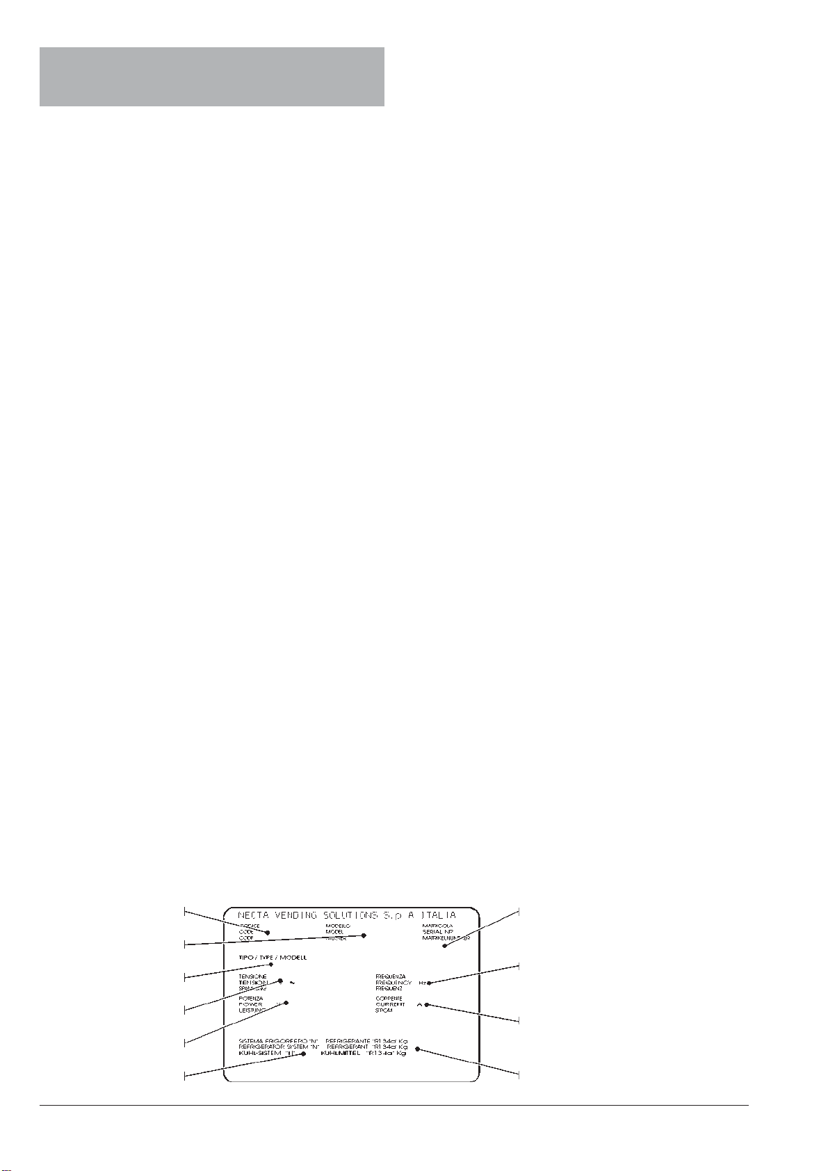
IDENTIFICATION OF THE VENDING
MACHINE AND ITS CHARACTERISTICS
Each machine is identified by its own serial number,
indicatedontheratingplateattachedinsidethecabineton
the right side.
This plate is the only one acknowledged by the manufac-
turer as identification of the machine, and carries all data
which readily and safely gives technical information sup-
pliedbythemanufacturer.Italsoassistsinthespareparts
management.
Absorbed power
Operating voltage
Type
Current
Frequency
Serial number
Model
Product code
Refrigeration system class Type and amount
of refrigerant